Calculation method of fastening the upper slope of the land bund for erosion and strength

Author: Hasanov Elgiz, Mammadov Ahad, Aliyev Hamlet
Journal: Бюллетень науки и практики @bulletennauki
Section: Технические науки
Article in issue: 6 т.7, 2021.
Free access
To protect the slopes of the ground dam from the devastating effects of wind waves, ice, water flow, precipitation and other factors, a number of engineering measures are provided. Based on this, an engineering decision is taken on the choice of materials for fastening structures, as well as methods for calculating their stability. When calculating the stability of the upper slope, two cases of a combination of loads and impacts are mainly considered. One of them is the reduction of the water level in the reservoir with maximum speed, and the other is the case when the water level in the reservoir is at the lowest operational level. The article investigates the processes of sliding of natural slopes of the upstream dam. Taking into account the combined action of the forces of filtering, weighing and vapor pressure, as well as the force of hydrostatic pressure to the level of dead volume. The equation for the stability coefficient of a circular-cylindrical slip of a uniform natural slope of the upstream dam has been obtained.
Protective coating, maximum wave velocity, slope, hydrostatic pressure, wave pressure force
Short address: https://sciup.org/14120578
IDR: 14120578 | UDC: 627.824 | DOI: 10.33619/2414-2948/67/20
Методы расчета устойчивости и размыва верхового откоса земляной плотины
Для защиты откосов грунтовой плотины от разрушительного воздействия ветровых волн, льда, водотока, атмосферных осадков и других факторов предусмотрен ряд инженерных мероприятий. На основании этого принимается инженерное решение по выбору материалов для крепления конструкций, а также методов расчета их устойчивости. При расчете устойчивости верхнего склона в основном рассматриваются два случая сочетания нагрузок и ударов. Один из них - снижение уровня воды в резервуаре с максимальной скоростью, а другой - случай, когда уровень воды в резервуаре находится на самом низком рабочем уровне. В статье исследуются процессы оползания естественных откосов верхней плотины с учетом совместного действия сил фильтрации, взвешивания, а также силы гидростатического давления на уровень мертвого объема. Получено уравнение для коэффициента устойчивости кругло-цилиндрической поверхности скольжения верхового откоса плотины.
Text of the scientific article Calculation method of fastening the upper slope of the land bund for erosion and strength
Бюллетень науки и практики / Bulletin of Science and Practice
UDC 627.824
Currently, the Republic of Azerbaijan faces a very urgent task of developing agriculture, developing new areas for agricultural land and providing irrigated areas with the required water rate. The recent events on the liberation of the occupied territories of the Karabakh region made it possible to improve water consumption in several regions. Reservoir complex Sugovushan built on the bed of the Tartar River in 1975 was put into operation. For about 30 years, this hydrojunction was in the occupied zone and was operated without fulfilling the conditions of the regulatory requirements for the operation of reservoirs. It should be noted that the influence of waves on the slopes of the dam leads to the destruction of the protective layer of the dam. This fact leads to the destruction of the structure, which entails the problem of irrigating the lands of 6 districts of Karabakh region. Therefore, the issue considered in this article is relevant. Ground dams are one of the main facilities for creating a floodwater reservoir out of river course. The strengths of their upper slope is calculated on identification of levels of the upper and lower boundaries [1]. Therefore, protection slopes of the upper slopes of ground slopes are calculated out of two levels: normal overloaded (or flood disaster) levels and dead storage levels.
Research and calculations
The lower boundary of the upper slope is determined according to the dead storage level (Figure 1).
iron-concrete
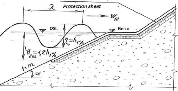
Figure 1. Scheme for Determination of the dead volume level of the lower boundary of the upper slope of the land bund
In most cases, the dead storage is considered a few meters above the lowest berm of upper land slop. According to observed cases it is desirable to have the depth of protective cover Hcr ≥ 2h1% of the lower boundary of the upper slope [2].
However, according to common practice in the design and engineering the dead storage level is often at the same level as the berm. For example, the DSL is at the level of 760,0 meter water reservoir built on the Araz River, on the upper slope of the Araz, at the border of Nakhchivan Autonomous Republic and Iran. Considering that the height of the wave as a result of the wind 10 meters above the surface of the water does not exceed h1%, then the lower boundary of the upper slope of the watercourse is DSL and slightly higher altitude can be considered. Therefore, it is reccommended that the depth of the depression between the dead storage level and the strength surface of lower border of the upper slope to be as Hdsl ≥ 1.2h1% (Figure 1).
When the level of the water in reservoir falls to ∇DSL as a result of the wind with impact of 1% and velocity (h 1% ) above 10 meters of surface, it is one of the most important issues to check the washing-out process at upper slope of the earth dam. To do so, it is necessary to know the maximum value of the motion velocity above the upper slope of that wave. At the level of the dead storage, heel point of the surface of the wave (profile) velocity is the smallest, when the pick of the wave reaches the highest level, the velocity of the water mass (c) in the heel section becomes maximum.
As noted, the strengthening point of the surface of upper slope is considered a few meters lower where the velocity of the wave reaches maximum (c). However, there is a practice in designing to strengthening of upper slope by covering with stone coatings where the wave velocity reaches maximum (c). Thus, it is important to know the maximum velocity of the wave to determine whether the bottom layer is washed or the wave impact towards the each piece of coverup. By determination of the speed it is possible also to test the wash-out of the concrete surface on the slope.
During the fluctuations in the dead storage level of the reservoir, according to the rule of continuity of flow, same amount of water flows from the depth (h) of wave hole to the H0 depth wave peak. Therefore, to find the maximum (c) velocity of the wave, it is necessary to use the continuity of the flow (absolute) and Bernoulli equations (Figure 2). These equations are expressed as follows [3]:
cbh cosa =ubH0 cosa , (1)
h +
c2cos2a 2g
= ltga + H0 +
v2cos2a 2g
where: b — width of the flow of water flowing as a result of the upstream fluxing process; v — velocity of movement of the water flow mass at the wavelength; a — angle between the upper slope and the horizontal line, below the dead storage level: a = ctg m; m — coefficient of the earth dam below the dead storage level.

Figure 2. Hydraulic calculation scheme of fluctuation process when level of water falls into dead storage level in reservoir
In the equation (2), the pressure of the resistance caused by erosion during the flow of the wave in upper slope has not been taken into consideration. From the equation (1) we find the velocity of the flow at the wave peak as follows:
hc
V=H0
If we replace formula (3) in equation (2), then it looks like below:
h +
c2cos2a 2g
= Atga + Ho +
c2cos2a h2
2g H2
The maximum (c) velocity of the wave (4) can be found as follows:
c2cos2a h2 A
-^ -(--^g^1-- ^
h0 2g
c =---- п2 b2 l?tga + H0 -h )
cosa Hg — h2 \2
As formula (5) describes, it is theoretically possible to calculate the maximum height of water mass flowing over the upper slope surface (c), wave length (λ), depth of the pick and the heel of the wave (H0 — h). Thus, since A, H0 and h parameters are possible to set experimentally, we can calculate the velocity (c) by using the formula (5).
It is important to look at the attribution of hydrostatic and wave pressure loads of the water separately to enable the check for strength the bottom part of the water reservoirs below the dead storage level of the surface of monolithic vascular concrete pans. The hydrostatic pressure of the water can be determined in two cases. In the first case when the water in upper byef is in dead storage level, the hydrostatic pressure epirus becomes in the form of a rectangular triangular and maximum value of the epilent becomes at the lower edge of reinforced concrete pan of the slope calculated with equation (6):
P i s = YWH b о h = 1-2Y w h 1%
Since the width (b) of the water flow mass is constant, the pressure load forces are found in
the plane surface problem. In this case, the force generated by the pressure load is as follows
(Figure 3):
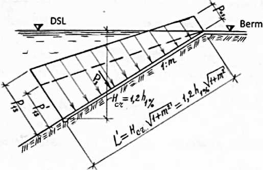
Figure 3. Scheme of determination of hydrostatic pressure load affecting the lower part of the upper
slope cover
P = 1Pi s^ = 0.6Ywh1%^ 1 + m2
In the latter case, the hydrostatic pressure epithelium is in the form of a rectangular trapeze when the water is in the normal drowning level. The top and bottom seats of this episode are defined as follows:
( Pos = YW(VNBS - VDSL) = YwHWorking
{Pis = YW(VNBS - VDSL + HDSL) = Yw(HWorking + 1.2hi%)
^ working — is a working pressure on the water reservoir's working prisma
(between the levels of VNBS and VDSL)
Taking into account the equation (8), hydrostatic pressure is calculated as follows:
Ps = ?(POs + Putt = 1.2Ywhi%(Hi9f i + O.bh^l + m2
In comparison of formulas (8) and (9), it is desirable to use the formula (9) for verifying the strength of the reinforced concrete ceiling below the VDSL. Given the impact of these hystrostatic pressure loads along the length of the sloping part, the monolithic reinforced concrete coating on the ground environment can be calculated as bending deformations as a console structure.
It is possible to calculate the force by determining the cost of the pressure epartment divided into 4 parts, from the heel to the peak on the surface of the wave to find the maximum impact strength of the wave pressure to the upper slope of the ground beneath the dead storage level of the reservoir. At the L1 longitudinal section of the slope, the wave crosses at the point where the surface of the wave is at the forefront of berm, so you can take 75% of the area completed to rectangle to find the area of this episode (Figure 4):
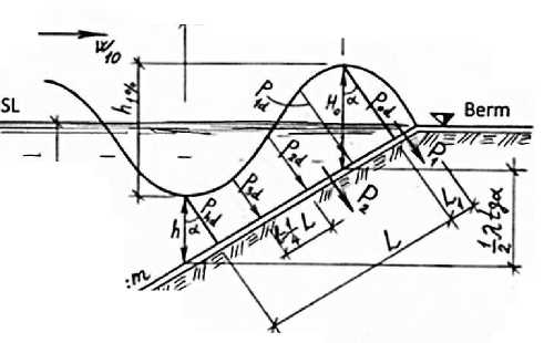
Figure 4. Determination scheme for maximum pressure load in the fluctuation process when the water level drops to DSL
P 1 = Y w P od L i
The strength of the pressure and value from the heel of the wave to the pick can be calculated by Simpson's rule [4].
P1 = iKPod + 4Pid + 2P2d + 4P3d + Phd)
Here, the distance between the orbits of the wave pressure load: l=L/4;
The L-wave's pressure load epide has a length and is found in Figure 2 and 4 using geometrics:
L = 1^1 + tg2a + (H0 — h)slna ;
Pod, P1d> P2d, P3d, Pdd.- are wave pressure coordinates and been calculated as follows:
Pod = YwH0cosa; Pid = Ywhicosa; P2d = Ywhicosa;
P3d = Ywhicosa; Phd = Ywhcosa;
If we replace the expression (12) and (13) in (11), the formula becomes as following:
^2 = 12 [^^^^д^а + (^0 - h)sina^ Ywcosa(H0 + 4h1 + 2h2 + 4h3 + h)
The ultimate pressure load on the upper slope of the wave is as follows:
Pd=P1+P2
If we apply (10) and (14) statements in (15), we obtain the following formula for calculating the force generated by the wave's final pressure load:
Pd=1Yw\1(Ho
4 3
+ 4h1 + 2h2 + 4h3 + h) [ 1^1 + tg2a + (Ho — h)sina]
+ +3H o L i }
cosa
Thus, using the formula (5), (9) and (16), it is possible to find the maximum speed, the hydrostatic pressure force and the force generated by the pressure of the known wave.
References Calculation method of fastening the upper slope of the land bund for erosion and strength
- Мамедов К. М., Мусаев З. С. Гидротехническое оборудование. Баку, 2006.
- Мусаев З. С., Мамедов К. М., Махмудов Т. М., Исмаилов Ф. М., Зарбалиев М. С. Гидотехнические сооружения. Баку. 2016.
- Мусаев З. С., Мамедов К. М., Махмудов Т. М. Гидравлика и гидравлические машины. Баку, 2005.
- Мурсалов А. А. Методические указания по вопросам моделирования гидротехнических сооружений. Баку, 2016.
