Calculation of electric direct current circuits with diodes

Author: Khmelnik S.I.
Journal: Доклады независимых авторов @dna-izdatelstwo
Section: Electrical Engineering
Article in issue: 22, 2013.
Free access
In [1] has been described (in particular) method for calculation of electric direct current circuits with diodes. Here are given programs in the MATLAB with open source to solve this problem.
Short address: https://sciup.org/148311917
IDR: 148311917
Text of the scientific article Calculation of electric direct current circuits with diodes
In [1] describes (in particular) the method of calculation of electrical direct current circuits with diodes. There are open source MATLABprograms for such calculations. Data for the calculation prepared in tabular form. Dimension of the task is limited only by computer resources.
Initially, the electric circuit nodes are numbered in random order. Branches electric circuits are determined by the numbers N1 initial and N2 end node. A branch may contain a resistance R , a constant voltage source U and a diode D . The choice of which of the two nodes to designate initial, has value only if the branch contains a diode. The initial node is assigned one that is adjacent to the positive pole of the diode.
Current (defined as a result of the calculation) has a positive direction from the initial to the final node.
Description of the electric circuit is an array of B . Each row of the array describes one of the branches and has the following form:
B(k,:) = [N1,N2,R,U,D]
In this case, D=1 , if the diode is in the branch, and D=0 otherwise.
In addition, the electric circuit may include current sources, are included among the total points and some node. The positive direction of current from the source is sending to the node.
Description of current sources is an array following form:
C=[C1,C2,...,CN,...], where each node N we associate the number of CN - the current value of the current source, or zero if in this node is not a current source.
3. On the nodal current sources
In a real electric circuit current source is included in some branch. To bring this electric circuit to the "canonical" form (described above), do the following:
o converts the source of the current in a separate branch (not containing other elements)
o convert a branch in the two current sources, as in the electric circuit shown in Fig. 1 - see the transformation a--->b.
Obviously, the canonical electric circuit must satisfy the condition
sum(C)=0.
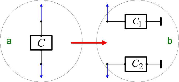
Fig. 1.
4. Calculation electric circuit
The calculation electric circuit is performed iteratively and the result of calculation, as a rule, is approximate. In this case, due to appear residuals - the deviation from zero in the equations of Kirchhoff's laws. They correspond to the relative error violations of these laws. The relative error violations the first law of Kirchhoff defined as the ratio of the mean square residuals of the first Kirchhoff's law to the mean square of the currents in the branches, and the relative error violations of the second law of Kirchhoff defined as the ratio of the mean square residuals for the second Kirchhoff's law to the mean square of the voltage on the branches (created voltage sources and current sources).
The value of the permissible relative error in violation of the second Kirchhoff's law is given by the user.
The number of iterations (i.e. duration of the calculation) and the error performance of the first law Kirchhoff adjust the amount of so-called "methodical" resistance. It makes sense the resistance included between each node and a common point. This resistance must be much greater than all the resistance branches (not counting reverse resistance diodes). The greater this resistance, the higher the accuracy of compliance of the first law of Kirchhoff, but the longer the duration of the calculations.
5. Program Description
M-function for the calculation is as follows:
function [i,f,er1,er2,k,p,E,N,y,m]=...rucd(B,C,r,erd,dmin,dmax,n)
Input arguments here are
Output values here are i –an array of current of branches f –the array of nodal potentials er1 – relative error violations the first law of Kirchhoff, er2 – relative error violations of the second law of Kirchhoff, k – the number of iterations p –the array of residuals in the branches of the second law of Kirchhoff,
E – the array of potential difference between the nodes of branches,
N – the array - incidence matrix, y – the array of residuals in the nodes of the first law of Kirchhoff, m – a flag of the result, where
• m=0, if the calculation is made;
• m=1, if the calculation is not carried out due to violations of conditions of sum(С)=0; then get a message msg=sum(С);
• m=2, if in table nodes met the node number, exceeding a specified number of nodes; then get a message is msg='greatest number'.
6. Example of a "canonical" form
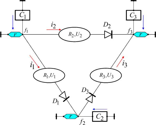
Fig. 2.
Fig. 2 shows a simple electric circuit with diodes. Here r – methodical resistance, which is absent in the real electric circuit. For this electric circuit these arrays are as follows:
B=[1,2,R1,U1,D1;...
1,3,R2,U2,D2;...
2,3,R3,U3,D3];
C=[C1,C2,C3]';
7. Test
Test M-function function test()
calculates the electric circuit shown in Fig. 3.
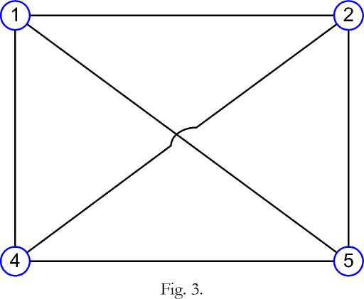
The presence of certain elements of the branches and sources of current determined in the arrays B,С .
List of programs
-
1. function test()
-
2. function [i,f,er1,er2,k,p,E,N,y,m] =rucd(b,C,ro,erd,dmin,dmax,n)
-
3. function [N,nuz] = makingN(branch)
-
4. function [R,U,D] = makingRU(branch)
-
5. function [f,i,k,er,erk,p,Un]=
-
6. func t i o n [i,k,er,p]=
-
7. function [mui1,mui2]=Rdiod(i,D,dmin,dmax)
nocondel(R,ro,N,U,C,erd,D,dmin,dmax)
min243(Rn,Un,erd,D,dmin,dmax)
function test()
dmax=10000;
r=100000;
erd=0.0001;
n=4;
[i,f,er1,er2,k,p,E,N,y,m]=rucd(B,C,r,erd,dmin,d max,n);
er1
er2 k
m function [i,f,er1,er2,k,p,E,N,y,m] =rucd(b,C,ro,erd,dmin,dmax,n,kmax) % main function if sum(C)==0
m=0;
else m=1;
msg=sum(C)
i=0;f=0;er1=0;er2=0;k=0;p=0;E=0;N=0;y=0;
return end
[N,nuz] = makingN(b);
if nuz>n m=2;
msg=nuz i=0;f=0;er1=0;er2=0;k=0;p=0;E=0;N=0;y=0;
return end
[R,U,D] = makingRU(b);
[f,i,k,er2,er1,p,E]=nocondel(R,ro,N,U,C,erd,D,d min,dmax,kmax);
y=f/ro;
function [N,nuz] = makingN(branch)
% the creation of the incidence matrix
% b = begN, endN raz=size(branch);
nb=raz(1);
uz = 0;
k = 1;
while k <= nb a = branch(k,1);
if a > uz uz = a;
end b = branch(k,2);
if b > uz uz = b;
end if a > 0
N(a , k) = -1;
end if b > 0
N(b , k) = 1;
end k = k + 1;
end nuz=uz;
n=size(N);
nuz2=n(1);
if nuz==nuz2
else nuz nuz2
msg='Numbers of Nodes?' end function [R,U,D] = makingRU(branch)
% R,U,D from branches
% b = uzbegN,uzendN,R,U,D raz=size(branch);
nb=raz(1);
uz = 0;
k = 1;
while k <= nb
R(k,k) = branch(k,3);
U(k) = branch(k,4);
D(k) = branch(k,5);
k=k+1;
end
U=U';
function [f,i,k,er,erk,p,Un]=...
nocondel(R,ro,N,U,C,erd,D,dmin,dmax,kmax) % basic calculations
Rn=R+ro*N'*N;
Un=U-ro*N'*C;
[i,k,er,p]=min2_4_3(Rn,Un,erd,D,dmin,dmax,kmax)
f=ro*(N*i+C);
raz=size(N);
nf=sum(f.^2)/raz(1);
ni=sum(i.^2)/raz(2);
erk=sqrt(nf/(ro*ro*ni));
func t i o n [i,k,er,p]=...
min243(Rn,Un,erd,D,dmin,dmax,kmax)
% min. function (1.1.24)
i=0*Un;
nUn=sum((Un).^2);
er=999;
k=0;
while er>erd & k [mui1,mui2]=Rdiod(i,D,dmin,dmax); p=mui1'+Rn*i-Un; np=sum((p).^2); er=sqrt(np/nUn); if er==0 break; end m2=diag(mui2); a=p'*p/(p'*(m2+Rn)*p); ap=a*p; i=i-ap; end function [mui1,mui2]=Rdiod(i,D,dmin,dmax) % resistance of diodes n=size(i); n=n(1); k=1; while k<=n if D(k)==1 if i(k) >0 mui1(k)=dmin*i(k); mui2(k)=dmin; else % i(k) =<0 mui1(k)=dmax*i(k); mui2(k)=dmax; end else mui1(k)=0; mui2(k)=0; end k=k+1; end
