Calculation of heat transfer characteristics of a finned wall

Author: E. N. Vasil'ev
Journal: Siberian Aerospace Journal @vestnik-sibsau-en
Section: Aviation and spacecraft engineering
Article in issue: 2 vol.21, 2020.
Free access
The reliability and resource of the radio-electronic equipment of the spacecraft is increased by ensuring op-timal temperature conditions. Thermal control systems maintain the set temperature mode and heat removal from the onboard equipment to the surrounding space. Finned heat exchangers are an important element of the de-sign of thermal control systems, which allows intensifying the heat transfer process. The calculation of the char-acteristics of finned heat exchangers must be carried out taking into account their parameters and the physical properties of the heat transfer agent. The organic liquid LZ-TK-2, which has a very low freezing point and other useful performance characteristics, is considered as a heat transfer agent. The dependences of the local heat transfer coefficient of the LZ-TK-2 heat transfer agent on the wall temperature are calculated using criteria equations. Based on the numerical solution of the two-dimensional problem of thermal conductivity, the tempera-ture fields in finned walls of various configurations are determined. Calculations of the heat transfer coefficient of the finned wall of the heat exchanger were made in two model approximations, the error of using a simplified approximation that does not take into account the temperature dependence of the local heat transfer coefficient was determined.
Thermal control system, heat transfer coefficient, finned wall, heat exchanger, heat transfer agent LZ-TK-2.
Short address: https://sciup.org/148321741
IDR: 148321741 | UDC: 536.2 | DOI: 10.31772/2587-6066-2020-21-2-226-232
Text of the scientific article Calculation of heat transfer characteristics of a finned wall
Introduction. The thermal control system (TCS) of a spacecraft performs the most important function for ensuring optimal temperature conditions for all units and subsystems in real operating conditions [1–5]. In TCS finned surfaces that are in contact with a liquid or gaseous heat transfer agent are widely used to intensify heat trans- fer and reduce dimensions in heat exchangers. The characteristics of the TCS depend on the parameters of the finned surfaces and the thermophysical properties of the heat transfer agent; therefore, the development of the TCS requires solving a number of problems, such as determining the local heat transfer coefficient on the contact surface of the wall and the heat transfer agent, calculating the heat transfer characteristics of the finned wall and optimizing its parameters.
The heat transfer characteristics are calculated by the temperature field in the volume of the finned wall obtained from the solution of the heat conduction problem. As a rule, when solving the heat conduction problem various simplifying assumptions are made: temperature gradients over the thickness of the fin are neglected (approximation of a thin fin), a uniform temperature distribution is taken at the base of the finned wall, a constant value of the heat transfer coefficient over the finned surface is set, etc. [6]. So that such simplifying assumptions do not lead to significant calculation errors, it is necessary to verify the validity of their application for each task.
The characteristics of the heat transfer process of the finned wall and a heat transfer agent depend, on the one hand, on the heat transfer coefficient of the heat transfer agent on the surface of the heat exchanger, and on the other hand, on the conditions of heat transfer in the wall volume by the heat conduction mechanism. In this paper, we present the results of calculations of the wall heat transfer characteristics based on determining the dependence of the heat transfer coefficient LZ-TK-2 on the temperature of a finned surface and modeling the heat transfer process in a finned heat exchanger by numerically solving the two-dimensional heat equation without using the simplifying assumptions mentioned above.
Heat transfer coefficient of the heat transfer agent LZ-TK-2. According to the requirements of the TCS operation, the heat transfer agent must have a freezing point not higher than –80 °C, corrosion inertness to the TCS materials, fireproof, and have a number of other specific properties [7; 8]. As a working substance for the circuit, we consider the heat transfer agent LZ-TK-2, the basis of which is isooctane, which has a freezing temperature of –107 °C and includes anti-wear additives to reduce bearing wear of electric pump units. Description and temperature dependences of the physical properties of the heat transfer agent LZ-TK-2 are given in [8].
The calculation of the heat transfer coefficient was carried out taking into account the mode of motion and physical properties of the heat transfer agent, the geometric parameters of the finned surface. Depending on the Reynolds number Re = uD/ν, there are stable laminar (Re < 2·103), transitional (2·103 < Re < 104), and developed turbulent (Re > 104) modes, here u – is the coolant velocity, ν – is coefficient of kinematic viscosity. For a rectangular channel having a height a and a width b, the equivalent hydraulic diameter D = 2ab/(a+b) is usually used as a characteristic dimension. The value of the local heat transfer coefficient α at the “heat transfer agent-finned surface” interface was determined using criteria equations based on the results of experimental studies and similarity theory [9]. For the developed turbulent regime, an equation is used that determines the value of Nusselt number
Nu = 0.021 Re 0.8 Prh 0.4 3 (Prh / Pr s )0 - 25 e .
Prandtl number Pr = ν с ρ/λ is determined by the values of the kinematic viscosity coefficient ν, the heat capacity с , the density ρ and the thermal conductivity coefficient λ, corresponding to the average temperature of the heat transfer agent (Pr h ) and the wall surface temperature (Pr s ). If the channel length is more than 50 D , the coefficient value is ε = 1. The value of the local heat transfer coefficient LZ-TK-2 is calculated from the value of Nusselt number using the formula
Nu X
a =---
D
-
Calculations were performed for a = 2.5 mm, b = 1.3 mm and the coolant velocity u = 2.9 м/с, the value Re = 1.1·104 was obtained with a characteristic value V = ν = 0.45 mm2/s. The obtained dependences of the heat transfer coefficient α on the temperature of the wall surface T s are shown in fig. 1 for the heat transfer agent temperature values of 20, 40 and 60 °C. The figure shows that the value of α increases with an increase in both the wall surface temperature and the temperature of the heat transfer agent. The dependences α( T s ) are the initial data for calculating the temperature field of the finned wall.
Calculation of the temperature field in the finned wall. The task of thermal calculation is to determine the temperature field and heat transfer coefficient, which reflects the ratio of the transmitted heat power to the temperature difference between the heat carrier and the wall. We consider the process of heat transfer of a heat transfer agent LZ-TK-2 with a finned wall, the cross section of which is shown in fig. 2.
The calculation of the temperature field in the wall of the heat exchanger was carried out on the basis of solving the non-stationary problem of thermal conductivity. In the case of a thick fin in which the temperature gradients are comparable in width and height, a two-dimensional thermal conductivity equation of the form is numerically solved
d T „ ( d2 T d2 T cP— = X —т ■—t
8 1 ( d x 2 d y 2
-
The calculation area of the problem, which is half of a periodically repeated fragment of the finned wall, is highlighted in fig. 2 with a dashed outline. On the internal boundaries of the wall the symmetry conditions for the heat flow ∂T/∂x = 0 are set, and on the contact surfaces with the heat transfer agent (including the end surface of the fin), the boundary conditions of the third kind are set г 8 T т
-
X— + a T
-
8 1 J l = 0, L
q i = 0, l ’
here T – is the temperature, x, y – are the spatial coordinates, l = x , y and L – are the size corresponding to these coordinates, q – is the heat flux density. It was assumed that the temperature of the heat transfer agent in contact with the finned surface has a constant value.
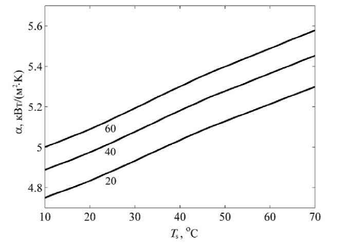
Fig. 1. Dependence of the local heat transfer coefficient LZ-TK-2 on the wall temperature
Рис. 1. Зависимости локального коэффициента теплоотдачи ЛЗ-ТК-2 от температуры стенки
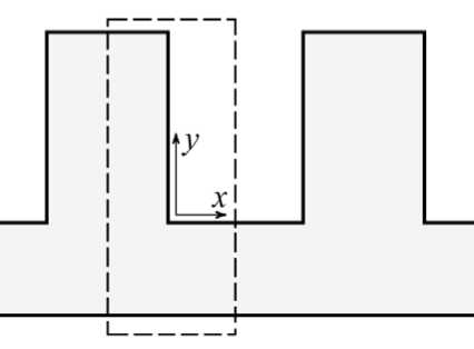
Рис. 2. Схема оребренной стенки и границы расчетной области
Fig. 1. Diagram of the finned wall and the boundary of the calculation area
To solve equations (1) and (2), we used the method of total approximation with splitting the problem by spatial coordinates [10–15]. The temperature field in the volume of the wall Δ T ( x , y ) and with distribution α( T s) has a mutual influence on each other, since α( T s ) determines the amount of heat flow at the border of the finned surface with the heat transfer agent. Coordination of these distributions occurs in the process of obtaining a steady solution to a non-stationary problem.
The wall material was considered to be steel 12X18N10T, which has a thermal conductivity coefficient λ =19 Вт/(м·К). The temperature of the heat transfer agent in contact with the upper finned surface was set constant and equal to 50 °C, on the lower surface of the base its value was 60 °C. The value of the local heat transfer coefficient α was determined in accordance with the values of temperatures on the surface of the wall and the heat transfer agent. Fig. 3 shows the temperature field for the following geometric parameters of the finned walls: fin thickness 1.5 mm, fin height 2.5 mm, wall thickness 1.6 mm, the distance between the fins b = 1.3 мм. The calculation was performed for half of a periodically repeated fragment of the finned wall, so the size of the base in the x direction is 1.4 mm in the figure. The temperature values for the corresponding isolines are given in degrees Celsius. At the base of the wall, the temperature gradient is observed in the y direction, and there are practically no temperature gradients in the x direction.
The fin has a temperature gradient in both directions. In this case, the temperature distributions of the lower surfaces of the base and fin are close to uniform, so it is legitimate to use simplified calculation models that assume uniformity of temperature.
A change in geometric parameters affects the nature of the temperature field. Fig. 4 shows the calculation results with decreasing thickness of the fin (0.7 mm) and the wall (0.5 mm), while the height of the fin and the width of the base did not change.
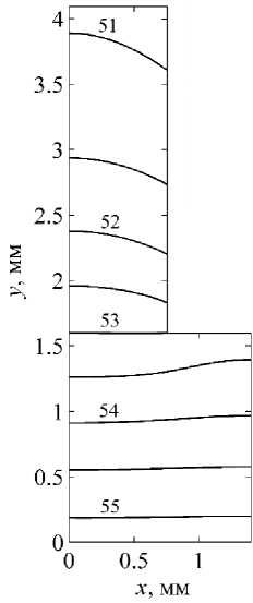
Fig. 3. Temperature field of the finned wall with the thickness of the fin 1.5 mm and the wall 1.6 mm
Рис. 3. Температурное поле оребренной стенки при толщинах ребра 1,5 мм и стенки 1,6 мм
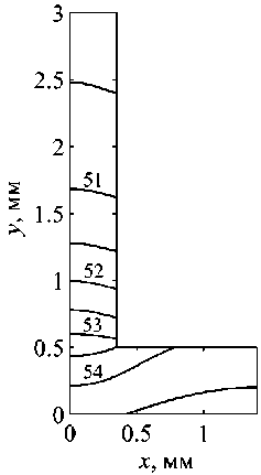
Fig. 4. Temperature field of the finned wall with the thickness of the fin 0.7 mm and the wall 0.5 mm
Рис. 4. Температурное поле оребренной стенки при толщинах ребра 0,7 мм и стенки 0,5 мм
At the base of the wall, the temperature field is substantially inhomogeneous already in both directions; in a thinner fin, an increase in the temperature difference in height is accompanied by a decrease in the transverse direction.
The heat transfer coefficient of the finned wall. The heat transfer coefficient k is an important integral characteristic of the heat transfer process of a finned wall with a heat transfer agent. Of greatest interest are the heat transfer characteristics in the volume of the wall and on the upper finned surface, therefore, we define the value of k as the ratio of the transmitted heat power to the temperature difference of the heat transfer agent T h and the lower smooth surface of the wall, as well as to the area of this surface. The total heat flux transferred by the wall to the heat transfer agent was calculated on the basis of solving the heat conduction problem from the temperature distributions of the upper finned surface T s and the local heat transfer coefficient α using the formula α( T s – T h). The heat flux was calculated in two model approximations. In the first case, the local heat transfer coefficient was determined taking into account its dependences on T s and T h , which are shown in Fig. 1, in the second, the value of α had a constant value corresponding to the surface temperature, i.e. the value α was set at T s = T h . Comparison of the calculation results allows us to estimate the error in applying the simplified mathematical model, which does not take into account the heterogeneity of the distribution of the heat transfer coefficient α over the finned surface.
When solving the problem of heat conduction on the lower surface of the wall base, an ideal heat supply was assumed, therefore, here the temperature was set with a uniform distribution and a value of T0. In the calculations, the value of T0 varied in the range of 30–70 °С; the temperature of the heat transfer agent in contact with the upper finned surface was fixed and equal to Th = 20 °С. Fig. 5 shows the dependences k(T0) obtained using both considered model approximations. Lines 1 correspond to the wall configuration shown in fig. 3, lines 2 refer to the wall shown in Fig. 4. The horizontal lines were obtained as a result of calculations with a fixed local heat transfer coefficient α, which leads to the constancy of the values of k. Growing graphs were obtained in the calculations taking into account the temperature dependence α(Ts, Th).
From the calculations of two model approximations, the dependences k ( T 0 ) were obtained, the difference between which increases with the growth of T 0 (fig. 5). The relative magnitude of this difference is shown in fig. 6. The largest discrepancy is expected to correspond to configuration 2, since higher temperature differences are set in the fin of smaller thickness, which ultimately leads to greater heterogeneity of the local heat transfer coefficient α over the finned surface.
In general, for the considered wall configurations, the maximum deviation, which is the error of the simplified model, does not exceed 5 %. Such an error value for many practical calculations is quite acceptable and the use of a simplified model for the considered configurations of the finned walls is justified. However, for other wall parameters and heat transfer agent properties, the discrepancy may be higher, therefore, in each case, the admissibility of the use of a simplified model requires justification and confirmation by evaluating the calculation error.
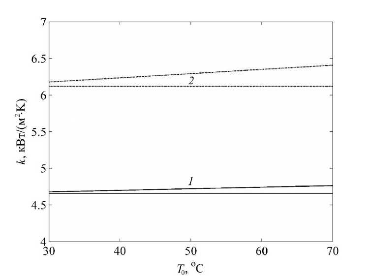
Fig. 5. Dependence of the heat transfer coefficient on the wall base temperature
Рис. 5. Зависимости коэффициента теплопередачи от температуры основания стенки
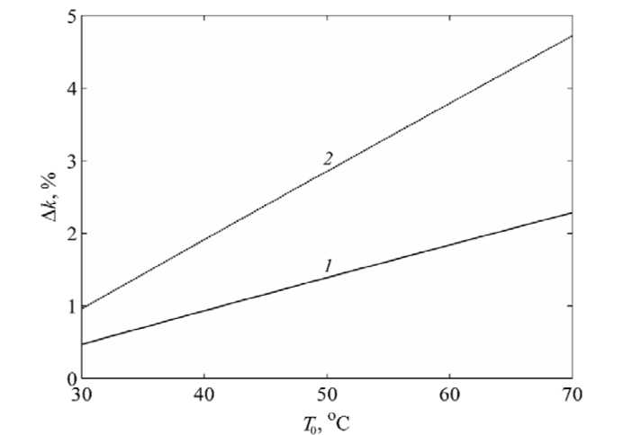
Fig. 6. Relative error in calculating the heat transfer coefficient in a simplified approximation
Рис. 6. Относительная погрешность расчета коэффициента теплопередачи в упрощенном приближении
Conclusion. Thus, the paper analyzes the heat transfer process in the finned wall of the heat exchanger. Based on the criteria relations, the temperature dependences of the local heat transfer coefficient α on a finned surface are obtained. The temperature field was calculated for two configurations of the finned wall, and the influence of the geometric parameters of the wall on the heterogeneity of the temperature distribution was estimated. The temperature dependences of the heat transfer coefficient are obtained using two model approximations that differ in taking into account α, the relative error of the simplified approximation is determined, which does not take into account the temperature dependence of the local heat transfer coefficient.
Acknowledgments. The reported study was funded by the Russian Foundation for Basic Research, the Government of the Krasnoyarsk Territory, the Krasnoyarsk Regional Fund of Science to the research project: “Theoretical and experimental investigation of heat and mass transfer processes in the two-phase systems of thermal control” (project № 18-41-242005).
References Calculation of heat transfer characteristics of a finned wall
- Chebotarev V. E., Kosenko V. E. Osnovy proyektirovaniya kosmicheskikh apparatov informatsionnogo obespecheniya [Foundation of information satellites design]. Krasnoyarsk, Sib. gos. aerokosmich. un-t Publ., 2011, 488 p.
- Kraev M. V., Zagar O. V., Kraev V. M., Golikovskaja K. F. Nestatsionarnye teplovye rezhimy kosmicheskikh apparatov sputnikovykh system [Unsteady thermal conditions of spacecrafts of satellite system]. Krasnoyarsk, Sib. gos. aerokosmich. un-t Publ., 2004, 282 p.
- Vasil’ev E. N., Derevyanko V. A., Kosenko V. E. et al. Vychislitel'nye tekhnologii. [Computational modeling of heat exchange in thermoregulation systems of space vehicle]. 2009, Vol. 14, No. 6, P. 19–28 (In Russ.).
- Vasil’ev E. N., Dekterev A. A. [Mathematical modeling of heat and mass transfer processes in the two-phase thermal control loop with the capillary pump]. Vestnik SibGAU. 2008, No. 4 (21), P. 12–16 (In Russ.).
- Vasil’ev E. N. Optimization of Thermoelectric Cooling Regimes for Heat-Loaded Elements Taking into Account the Thermal Resistance of the Heat-Spreading System. Technical Physics. 2017, Vol. 62, No. 9, P. 1300–1306.
- Roizen L. I., Dulkin I. N. Teplovoy raschet orebrennykh poverkhnostey [Thermal design of finned surfaces]. Moscow, Energiya Publ., 1977, 256 p.
- Morkovin A. V., Plotnikov A. D., Borisenko T. B. [Heat transfer medium for heat pipes and external hydraulic circuits of thermal control systems of unmanned and manned spacecraft]. Kosmicheskaya teknika i tekhnologii. 2015, No. 3, P. 89–99 (In Russ.).
- Morkovin A. V., Plotnikov A. D., Borisenko T. B. [Heat-transfer media for internal loops of thermal control systems for manned spacecraft]. Kosmicheskaya tekhnika i tekhnologii. 2013, No. 1, P. 79–87 (In Russ.).
- Karminsky V. D. Tekhnicheskaya termodinamika [Technical thermodynamics and heat transfer]. Moscow, Marshrout Publ., 224 p.
- Samarskii A. A. Teoriya raznostnykh skhem [The theory of difference schemes]. Moscow, Nauka Publ., 1989, 616 p.
- Dulnev G. N. et al. Primenenie EVM dlya resheniya zadach teploobmena [Application of computer to solving heat transfer problems]. Moscow, Vysshaya Shkola Publ., 1990, 207 p.
- Vasilyev E. N., Derevyanko V. V. [Mathematical model of heat exchange processes in honeycomb panels with heat pipes]. Vestnik SibGAU. 2010, No. 2 (28), P. 4–7 (In Russ.).
- Vasil'ev E. N., Nikiforova E. S. [Mathematical model of heat exchange processes in honeycomb panels with heat pipes]. Vestnik SibGAU. 2005, No. 3, P. 23–26 (In Russ.).
- Vasil’ev E. N. Calculation and Optimization of Thermoelectric Cooling Modes of Thermally Loaded Elements. Technical Physics. 2017, Vol. 62, No. 1, P. 90–96.
- Vasil’ev E. N. Calculation of characteristics of thermoelectric cooling system of heat-loaded elements of radio electronic equipment. Siberian Journal of Science and Technology. 2018, Vol. 19, No. 1, P. 17–21.
