Characteristics of low thrust liquid-propellant rocket engines testing process

Author: Nazarov V. P., Piunov V. Yu., Yatsunenko V. G., Savchin D. A.
Journal: Siberian Aerospace Journal @vestnik-sibsau-en
Section: Aviation and spacecraft engineering
Article in issue: 2 vol.22, 2021.
Free access
Low thrust liquid-propellant rocket engines (LTLPRE) are the main type of rocket engines for control systems of space aircrafts. The thrusters are able to work either in continuous or impulse regime, which is one of their main characteristics. The suggestion about engines` reliability should come from the results of tests which create real or greatly approximated to the real conditions. The development process of thrusters takes into a great account the problems of bench testing methodic, technical equipment of test benches for creating the closest possible to space conditions and the use of diagnostic methods and instruments for various types of physical research and dimensions. The ground test effectiveness depends on the level of real conditions imitation and the level of attention to all operational factors that influence the credibility of reliability parameter estimation during the development. One of the most important questions in terms of testing effectiveness is the question of testing result accuracy and credibility. The testing process of thrusters mainly goes under the requested conditions of vacuum, created in pressure chambers. To increase the effectiveness of space conditions imitation the paper suggests using the pressure chamber, equipped with the tube shield with the circulating liquid nitrogen under required mass flow rate. The impulse working regime creates instability of propellant moving in pipelines. The paper considers the methods of providing dynamically similar characteristics of supply systems in propulsion systems as well as conformity of hydraulic, inert and wave characteristics of supply pipelines.
Liquid-propellant rocket engines of low thrust, bench tests, space condition imitation.
Short address: https://sciup.org/148321809
IDR: 148321809 | UDC: 629.7.036.620 | DOI: 10.31772/2712-8970-2021-22-2-339-354
Text of the scientific article Characteristics of low thrust liquid-propellant rocket engines testing process
Low thrust liquid-propellant rocket engines (LTLPRE) are currently the main executive device in the control system of a spacecraft. They serve for orientation, stabilization and correction of the aircraft in space, and are also used in propulsion systems for orientation, stabilization and start-up in the upper stages, carrying out spacecraft launch into specified orbits [1].
The purpose of liquid propellant engines and conditions of their operation impose a number of specific requirements, in particular, the following:
– multimodality due to continuous operation (duration up to τ в > 103 s) and in various pulse modes with a minimum turn-on time of 0.03 s or less and with various pauses from 0.03 s to several days;
– a large resource in terms of accumulated operation time – up to 50,000 s and more;
-
– a large resource in terms of the total number of inclusions – up to 106;
-
– a possibility of any combination of switching times and pauses (negotiated in most cases);
Terminologically, in GOST 22396-77 “low-thrust liquid-propellant rocket engines” are defined as executive devices of a spacecraft control system with thrust from 0.01 to 1,600 N. Liquid-propellant rocket engines of low-thrust can be united by at least one common element (power frame, panel, fuel supply system, thermal insulation, etc.) [2–4].
The development of low-thrust rocket engines for domestic spacecrafts is carried out by the Design Bureau of Chemical Engineering named after A. M. Isaev (DBHimmash), the Scientific Research Institute of Mechanical Engineering (SRIMash), the Turaev Engineering Design Bureau "Soyuz" (TEDB "Soyuz)" [5– 7].
DBHimmash created 11 types of engines with thrust from 6 to 2250 N on two-component self-igniting fuel and 8 types on single-component fuel with thrust from 5 to 50 N.
These engines have found wide application in spacecraft for various purposes: ‘Soyuz-TM’, ‘Ekran’, ‘Prognoz’, ‘Spektr’, ‘Relikt’, ‘Coupon’, ‘Globus’, ‘Phobos’ and a number of others, as well as in the stages of reentry vehicles disengagement. They are designed for precise orientation, stabilization and correction of spacecraft orbit, for docking and undocking maneuvers with other vehicles. Motors are characterized by stability, efficiency, high-speed operation, reusable start-ups, start-ups duration from centisecond to hundreds and thousands of seconds.
Two-component low-thrust engines DST-25, DST-100, DST-100A, DST-200 and DMT-600, created at DBhimmash operate on the fuel components traditional for the enterprise – nitrogen tetroxide and asymmetric dimethylhydrazine. Reliability of operation and high performance are ensured by the use of a niobium alloy combustion chamber with a protective coating, radiation and internal film cooling.
The DMT-600 engine, which has an ablative cooling combustion chamber in combination with internal cooling, showed high energy and mass characteristics not only on traditional fuel, but also on monomethylhydrazine used in foreign practice [8].
Currently, the requirements for spacecraft, for their propulsion systems of control and for liquid propellant rocket engines are increasing, first of all, in terms of active shelf life up to 15–20 years, reliability and efficiency. The requirement to optimize the cost of development and manufacture comes to the fore, which can become a determining factor when choosing one or another engine [9; 10].
Despite the experience gained in the study of ongoing processes and the design of low thrust liquidpropellant rocket engines , a valid conclusion about the reliability of the created engines is only possible on the basis of their prototypes testing in real or substantially approximated to real conditions. Testing is a critical part of the program to create a highly efficient and reliable product.
Thus, live fire testing should be considered as a reasonably required stage of design and research work, which finishes with the creation of prototypes.
Basic requirements for testing LTLPRE
When creating liquid propellant rocket engines for spacecraft of various purposes, in the process of design (experimental) much attention is paid to bench tests approach, technical equipment of a bench simulating physical conditions effect of outer space, as well as the use of diagnostic methods and equipment for various physical research and measurements. In reliability assurance programs (RAP) of low-thrust engines, tests are the most important part, requiring significant financial, material and physical costs [2; 11].
As the number of tests of liquid-propellant rocket engines in full-scale operating conditions (flight tests) is very limited, and in most cases is generally excluded due to their high cost, the ultimate efficiency of their ground development should be achieved.
The efficiency of ground (bench) testing is ensured by simulating conditions of full-scale tests taking into account the influence of all operational factors affecting the accuracy of reliability indicators assessment during design testing in ground conditions. Requirements for ensuring the accuracy and reliability of test results occupy a special place in achieving test efficiency.
Certain requirements are imposed on benches for live fire tests of liquid propellant rocket engines, the main of which are as follows:
-
– achieving the degree of compliance with altitude conditions (rerefied environment);
-
– creation of the identity or dynamic similarity of characteristics of the liquid-propellant rocket engine power systems with fuel components, including correspondence of inert, wave and hydraulic characteristics of the supply lines;
-
– ensuring compliance with the laws of change of inlet pressures into the engine, pressures in the combustion chamber;
-
– ensuring the temperature values of the fuel components (both negative and positive) within the specified limits.
Most LTLPRE operate at very low ambient pressures, therefore, a significant amount of testing during their development should be carried out on benches equipped with vacuum systems. When determining the thrust and specific impulse characteristics in the vacuum chamber (with the engine installed in it for testing), the specified pressure value is provided for the uninterrupted flow of gas from the nozzle.
The dynamic processes that occur in the fuel lines for supplying fuel components depend on many factors determined by the properties of fuel components, pneumatic hydraulic circuit and the cyclogram of the LTLPRE. Therefore, to accurately determine engine characteristics during the tests it is necessary to ensure that the dynamic processes occurring in the bench lines are consistent with the processes occurring in the fuel supply lines in propulsion systems (PS) with LTLPRE.
There is no simple solution to this problem via identity design of the system supplying fuel components to the LTLPRE at the bench and in PS for a number of reasons:
-
– the need to ensure a high degree of safety during bench tests, which requires sufficient removal of fuel supply tanks from the vacuum chamber;
-
– the possibility of implementing various test programs at the bench, which is associated with the installation of additional fittings (valves, throttle devices and measuring instruments) in the fuel lines;
-
– design features of the bench.
It should be noted that at present, to meet the stated requirements, there are practically no standard measuring instruments that allow measuring instantaneous values of thrust and consumption of fuel components with the required accuracy. Therefore, when testing LTLPRE it is necessary to develop and use special measuring instruments and measurement techniques [2; 12].
Thus, the bench for LTLPRE live fire tests must have a system that ensures altitude conditions during the engine operation, a system for supplying fuel components to the engine with parameters that ensure the required test conditions, and a device for measuring thrust in pulsed and continuous modes.
When testing a liquid-propellant rocket engine, pulsed modes of its operation lead to excitation of oscillations in the test bench systems, which generally contribute to obtaining unreliable estimates of engine characteristics based on the test results. Wave phenomena in hydraulic lines lead to a difference between the required and actual nature and pressures values of the fuel components at the inlet of the components to the engine. Oscillations of the traction measuring device elements distort the estimates of the current thrust values and the nature of its change over time.
Elimination of oscillatory processes influence in bench systems on the results of live fire tests of LTLPRE in pulsed modes is an important condition for organizing these tests.
The parameters of high-altitude operating conditions of liquid propellant rocket engines are usually in the pressure range 10-2-10-5 Pa and depend on the spacecraft orbit in which they are installed. This has a significant impact on the processes taking place in the combustion chamber. For example, it has been experimentally proven that for N204 + UDMH fuel with a certain mixture formation system, the ignition delay value when the ambient pressure drops from 0.1 MPa to values close to zero increases from 0.001 to 0.01 s. LTLPRE have design pressures in the outlet section of the nozzle ра corresponding to high-altitude operating conditions. In the operation modes of the nozzle with overexpansion, when the ambient pressure ph exceeds the design pressure at the outlet of the nozzle ра and the degree of off-design reaches a certain limiting value, the supersonic flow is detached from the walls of the nozzle of the engine chamber, and oblique shock waves are formed in the nozzle. In this case, it is not possible to evaluate the actual (reduced to operating conditions) parameters of the tested engine [13].
The nature of the dynamic processes in the lines for supplying fuel components has a significant effect on the engine parameters, which is especially important for LTLPRE, since operation in pulsed modes that cause dynamic processes is one of the features of such engines. Pulse modes are accompanied by a change in the flow rates and pressures of the fuel components over time. Sharp changes in flow rate causes pressure waves, the magnitude of which largely depends on the geometry and elastic properties of the bench hydraulic systems pipelines. The dynamic processes occurring in the fuel lines also depend on other factors determined by the properties of the fuel components, the pneumatic hydraulic circuit and the cyclogram of the liquid-propellant rocket engine. When the frequency of pulsation of the fuel component coincides with the frequency of free oscillations of the component in the fuel pipelines, resonance is inevitable, which leads to a significant increase in the amplitude of pressure fluctuations, causing intense pressure pulsations in the combustion chamber of the LTLPRE. Therefore, to accurately determine the engine characteristics during the tests, it is necessary to ensure that the dynamic processes occurring in the bench lines are consistent with the processes that occur in the supply fuel lines in the propulsion system with LTLPRE [14; 15].
The evacuation system of the bench must create such a pressure in the pressure chamber so that during the entire time of LTLPRE operation uninterrupted outflow of gas from its nozzle is ensured, while in the study of the LTLPRE start-up characteristics - the pressure must correspond to altitude conditions (Fig. 1). As an alternative to the above requirements, it is possible to create test benches without maintaining the required pressure level in the pressure chamber. However, this approach significantly reduces the number and duration of LTLPRE start-ups, and determining the engine compliance with the given parameters is carried out indirectly, based on the pressures inside and outside the nozzle [16; 17].
In the interval (0, t 1 ), the pressure in the pressure chamber is in a state that is created by working vacuum pumps. At time t 1 the engine is started.
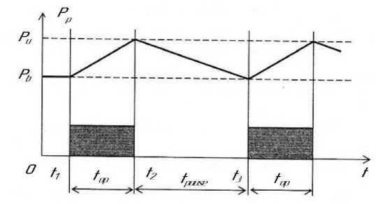
Рис. 1. Принципиальная схема изменения давления в барокамере: t раб – время работы двигателя; t паузы – время паузы между включениями; Р в , Р н – верхнее и нижнее допустимые значения давления в барокамере соответственно
Fig. 1. The principal scheme of pressure changing inside a pressure chamber:
T w – engine working period; t pause – time between working cycles;
P u P l – upper and lower limiting pressure values respectfully
In the interval (t1, t2) with the engine running, combustion products enter the pressure chamber with mass flow rate m(t).The mass of combustion products entering the pressure chamber during engine operation is t1
Мц = J m z( t ) dt . (1)
t 2
Also, in the interval ( t 1 , t 2 ), the vacuum pumps of the test bench are switched on at full capacity, which continue to operate in this mode and in the interval ( t 2 , t 3 ). The mass of the gas mixture removed from the pressure chamber by the vacuum system in periods from t 1 , before t 3 , is considered by the expression:
t 3
M выбр = Р ну J Q ( t ) dt , (2)
t 1
where ρ ну – density of the gas mixture under normal conditions; Q { t ) – volumetric capacity of the vacuum system, reduced to normal conditions..
Thus, the interval (tx, t2) is characterized by the fact that during this period a part of the gas mixture in amount of M1-2 is carried away from the pressure chamber by the vacuum system, and the remaining part of the gas mixture is determined by the formula t2
М б - р 2 = М z - M выбр = J [ m . ( t ) -Р ну Q ( t )>. (3)
t 1
The value of the mass must satisfy the condition of not exceeding the upper permissible limit Р u when filling the internal volume V bar of the pressure chamber.
Taking, with some assumptions, the gas mixture in the form of a mixture of ideal gases, we write down the expression for calculating the optimal value of the pressure chamber volume:
-
e - 2R t 2
-
V , = ' ' = ^ = J [ m . ( t ) - Р ну Q ( t ) ] dt , (4)
PвPвt 1
where R пс is the gas constant; T bar is the temperature of the gas mixture.
In the interval ( t 2 , t 3 ), the gas mixture M 1 - 2 remaining at time t 2 is evacuated from the pressure chamber by vacuum pumps. By the time t 3 , a pressure value equal to the lower permissible limit Р l should be reached. The average value of the vacuum pumps capacity for the interval ( t 2 , t 3 ) can be calculated as
M 1 - 2
q * ^ - бар . (5)
Р ну ( t 3 - t 2 )
A significant drawback of formula (4) is the accepted assumption that the functional dependences m ( t )and Q(t) are known, while in practice this is not always the case, since these dependences can only be obtained by carrying out a series of tests of the corresponding LTLPRE [18].
With a sufficient degree of reliability, it is possible to estimate the optimal volume of the pressure chamber from the known statistical values of the parameters that affect the volume. These parameters are: the average values of the total consumption of fuel components m . and the productivity of the vacuum system 0 * р in the range of permissible pressures in the pressure chamber from Р u to Р l.
Taking the test time of the engine under k start-ups according to the cyclogram (Fig. 1), k τ = k ( t + t ), the average values of the masses for k start-ups will be as follows:
M ∑ = m ∑ kt раб ; M выбр = ρ ну Q ср kt раб ; M бар = ρ ну Q ср kt паузы
For the values of masses of combustion products entering the pressure chamber when the engine is started and removed from the pressure chamber during the period t work , we obtain:
M б * ар = M ∑ * - M в * ыбр = kt раб ( m ∑ * - ρ ну Q с * р).
Then the final expression for estimating the internal volume of the pressure chamber of the test bench according to statistical data is
*
* бар
M бaр R пс T бар R пс T бар kt раб
= ( m * ∑ - ρ ну Q с * р ).
в
в
Thus, the obtained dependence, when organizing the process of fire tests of LTLPRE allows:
– to evaluate the required internal volume of the pressure chamber V * for the values of Р в, τ , k , m * specified by the test program, and the accepted productivity of the vacuum system of the bench Q * ;
– to determine the permissible number of engine starts k under known values of other quantities included in the formula (7), with the provision of the requirement Р бар ≤ Р в ;
– to evaluate the required performance of the bench vacuum system Q * at the accepted value V * , ensuring the execution of the test program, which sets the values of Р в , τ , k , m * ;
– to evaluate the possibility of testing a specific LTLPRE with the provision of the condition Р бар ≤ Р в at the given program Р в , τ , k , m * on a test bench with indicators V * и Q * .
Based on the analysis of expression (7), it follows that for small numerical values of P u , the quantity V * can take on such relatively large values that it will require a significant decrease in the number of k inclusions while maintaining the pressure in the pressure chamber within the specified limits.
To improve the efficiency of simulating altitude conditions, it is proposed to use a pressure chamber with a tube shield, into which liquid nitrogen is supplied at the required flow rate (Fig. 2).
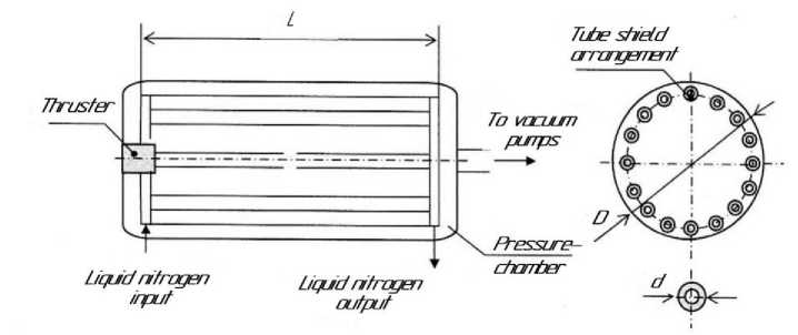
Рис. 2. Схема расположения трубчатого экрана в барокамере
Fig. 2. The scheme of tube shield arrangement inside a pressure chamber
The shield cooled by liquid nitrogen ensures the deposition on it of the combustion products of the fuel components formed during the operation of the tested LTLPRE, which significantly increases the time for maintaining a given pressure (vacuum) in the pressure chamber at the nozzle output of the combustion chamber during engine operation. In this case, the calculated (without separation of the flow from the nozzle wall) mode is maintained not only by the volume of the pressure chamber, but also by the deposition of the combustion products of the fuel components on the cooled shields. With the length of the tube shield L, the outer diameter d and n of the pipelines that make up the shield, it is possible to obtain the relationship between the engine operation time, the total consumption of fuel components and the geometric dimensions of the tube shield:
t раб = πρ тв пс δ nL * , (8)
km∑ where δ, ρ are the layer thickness and density of combustion products deposited on the shield, respectively.
According to the experience gained while conducting live fire tests of LTLPRE under vacuum conditions at the test facility of one of the rocket and space industry enterprises, the thickness of combustion products deposition on the tube shield with the practical preservation of the deposition efficiency is δ = 0,8…1,0 mm. The combustion products deposited on the tube shields have a structure similar to the snow cover, with the density (0.4…0.6) ⋅ 103 кг/м 3 [ 14; 18 ] .
Taking into account statistical values, the approximate formula for calculating the maximum possible live fire operating time of the engine between two successive shield defrosting processes has the form t∑ = K1nL d* , (9)
m∑ where К1 = 1.0…1.9 – empirical factor.
Taking into account nd ≈ 0,8 π D according to fig. 2 we obtain
V t∑ =K2 *бар , (10)
m∑ ⋅ D where K2 = 3.2///6.1 – coefficient; D – inner diameter of the pressure chamber.
Dynamic equation of fuel components supply lines
Pulse modes of LTLPRE operation initiate unsteady (low-frequency) processes of movement of fuel components in pipelines. Optimization of LTLPRE live fire tests requires solving the problem of dynamic similarity of the engine supply systems characteristics with fuel components on the bench and in the propulsion system, including the correspondence of the hydraulic, inert and wave characteristics of the supply lines [14; 15; 18].
The conditions for hydrodynamic processes similarity arising during unsteady motion of an incompressible fluid can be described using the well-known differential equations of unsteady motion and fluid continuity (Navier – Stokes equations) [19].
To study the unsteady motion of a viscous incompressible fluid in the bench pipelines, we use the following scale or basic values: T – time characteristic of the process; L – linear dimension; С иp * are the velocity and pressure known at a selected point of the liquid medium at a given time, respectively.
Analysis of the known Navier – Stokes equations, reduced to dimensionless form, shows that for the similarity of two or more hydrodynamic processes, the same coefficients Sh, Eu, Fr, Re must be the same (idem). Thus, the hydrodynamic similarity of the fuel components lines in the propulsion system and at the bench will be achieved by matching the coefficients:
L p *
Sh = = idem, Eu = = idem, Fr =
CT ρ C 2
C 2
gL
CL
= idem, Re = = idem,
υ
also the congruence of Mach numbers M = C / a , dimensionless wave resistance α = ρ Са / р* and relative friction losses Δ р / р* (where ρ , υ are the density and kinematic viscosity of the fluid, respectively; a is the reduced sound speed in system "pipeline-liquid") [20].
Inertia is one of the elements with which hydraulic systems models are formed. Assuming for the analysis of the inertial characteristics of the pipeline that its section (Fig. 3) is filled with an inviscid incompressible fluid, we can write the dynamic equation of the pipeline supplying the fuel component to the LTLPRE as follows:
dm ρ c 2
j +ζ =p -p +p вх вых m dt 2
where j is the coefficient of inertial losses; l - length; F - the flow area of the pipeline section; m - second liquid consumption; р вх, р вых – pressure at the inlet and outlet of the pipeline section, respectively; р т is the pressure of the mass forces of the liquid column on F area; ζ – coefficient of hydraulic resistance [20; 21].
To determine the requirements for bench pipelines for fuel components supply in LTLPRE with pulsed operation with frequency f , let us consider the question of the natural frequency of fluid oscillations in the pipeline f 0 . Free vibrations, and first of all the frequencies of free vibrations (natural frequencies), are the determining factors when considering the dynamic characteristics of bench lines. With a frequency ratio f 0 ≈ f in the bench fuel lines, resonance is inevitable, and processes that significantly affect the operation of the tested LTLPRE
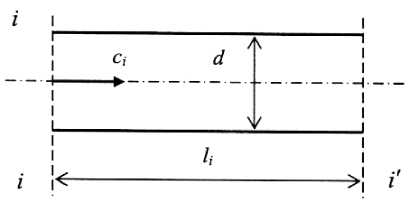
Рис. 3. Гидравлическая схема участка трубопровода
Fig. 3. The hydraulic scheme of pipeline area
will be initiated. This will lead to unreliable estimates of engine parameters based on test results.
ω о = 2/( τ е τ и ), (12)
where τ е = pL ( ρ Ca 2) – capacitive time constant; τ и = ρ сL / p = mL / pF – inertial time constant. For thin-walled cylindrical pipes the sound speed in terms of the walls elasticity
at
a ∞ t
E , 1 +χ ж
F
E тр
where a ∞ t is the sound speed in an unlimited volume of liquid, with regard to the current temperature T ; a ∞ t = a ∞ +β t ( T - T 0); a ∞ – the sound speed in an unlimited volume of liquid at a temperature Т о ; β t – temperature coefficient; Е ж , Е тр – the elastic moduli of the fluid and the material of the pipe walls, respectively; χ = D / δ – dimensionless parameter of the pipe, D and δ – diameter and thickness of the pipe walls, respectively [15;20; 22].
Having performed the substitution and taking into account that f = ω /2 π , we obtain the dependence of the natural frequency on the pipeline parameters and liquid characteristics (fuel component):
fo =
a « 1 V2
2 n l 1 +
D E ж
5 E тр
Resonant frequencies have the following meanings:
= i + 2 n E~
4Пl УРж , where n = 0, 1, 2, ... ; см = ^Еж / Рж — the speed of disturbances propagation in the line (sound speed); l is the line length.
The problems of low-frequency dynamics (up to ® 20 Hz), including the problems associated with the study of fluid movement in bench hydraulic lines, can be described with a sufficient degree of accuracy by simple dependencies if the pipeline is considered as a system with lumped parameters. The compressibility of the fluid and deformation of the pipe walls have little effect on the unsteady hydrodynamic process if
Т >> l 1^ = ,
Ежcм, where T is the time characteristic of this process.
In this case, the length of the hydraulic line f max should be significantly less than the wavelength Х пр of the highest process frequency f mах taken into account in the calculations.
Taking the speed of longitudinal waves propagation equals to the speed of sound in the liquid a and the wavelength Х пр = а / f ax , we write
a
.
max fn max n
When assessing the dynamic characteristics of LTLPRE under pulsed modes, the arising in a thrust device (TD) inertial forces can introduce significant errors in evaluating parameters that determine the dynamic characteristics. The error in measuring these parameters increases when the frequency of the pulsed mode of the tested LTLPRE is in the range of the natural frequency of TD due to the resonance effect. Therefore, when creating TD, it is necessary to ensure a significant excess of natural frequency f over the pulse mode frequency f .
It is worth noting that the solution to the problem of reducing the error, arising from the dynamics of pulsed modes of LTLPRE operation, is possible by including in the test bench calibration devices that correct the inertial forces in real time. This method significantly increases testing material costs and also reduces the reliability of the test bench [14; 18].
Performance optimization of bench lines
Proceeding from the main requirement that determines LTLPRE live fire bench tests organization is obtaining reliable information about the engine performance under operating conditions; the main criteria for bench lines performance optimization are formulated as:
-
– propellant components flows in bench lines and spacecraft lines should be similar;
-
- oscillatory processes arising as a result of operating pulse modes of the tested LTLPRE should not cause additional errors in the assessment of its performance [16; 19; 21].
The hydrodynamic similarity of the fuel components lines in the spacecraft and on the bench is achieved by the correspondence in the equations of fluid motion with the coefficients of the same name Sh, Eu, Fg, and Re, as well as by the congruencies of Mach numbers, dimensionless wave drag a and relative friction losses, A p / p * then, for a given fuel components consumption m с, taking into account m = c p F, we obtain:
IF p pF 2 p
Sh = —- = idem; Fu = -—у = idem;
mt ( m )2
Fr =
( m )2 ml
-------—- = idem; Re = — = idem.
( j + g ) F 2 l p 2 и F
As the tests must be carried out in full-scale conditions, the equations for the spacecraft and the bench are true:
t ст t KA ; m em ; р ст p KA ; U ct U KA .
After some transformations, with respect to the presented equations, we obtain the following conditions for the similarity of the bench and spacecraft lines:
Eu • Fr = — p— = idem или--—--- =--- Р КА ---= idem;
( j + g ) 1 ( j cm + g)l ст ( J ia + g У А
Re = — = idem или -ст- = -КА- .
F F ст F КА
The last expression can be represented in terms of the diameters of the main lines of the stand Dст and spacecraft Dка in the form
1 ст / d ct = 1 КА / D KA .
The dependence of the natural frequency of liquid oscillations in the pipeline on the characteristics of the fuel component and the pipeline is expressed by the formulas
fo =
a да t "^
|
2nl N |
DE 1 +--ж 5 E тр |
|
ИТТИ 1 z= ----- |
a да t |
|
или I — |
~ 2D E^ |
|
n f 0. |
2 +--ж |
|
8 E_ |
|
|
тр |
To exclude the resonance phenomenon, which causes negative (in terms of similarity) non-stationary processes, the natural frequency of the lines should differ significantly from the frequency of forced oscillations excited by the pulsed operating mode of the tested LTLPRE. The following dependence of the frequency f 0 and the maximum frequency of forced oscillations f дв max can be taken with respect to the safety factor f 0 > nf двmaх .:
Taking the value of the coefficient n = 10 and considering that the value a significantly exceeds the value P t ,, i.e. aда >> P t (Т - Т 0), the formula can be transformed:
1ст max nfдв max
0,1 a
2 D E
2 + ж
5 E тр
,
where l ст max – the maximum value of the bench pipeline length.
In the obtained expression, the known values are: frequency f дв max , determined by the test program for a specific LTLPRE, values a and Е ж - characteristics of the corresponding fuel component. Also known are the elasticity moduli for stainless steels of 12X18H10T type. The unknown variables are D and 5 .
Taking into account the dependence X min пр = a / f max ,, where a is the sound speed in a liquid, we write l ст ^ 0,1 a / f дв max или l crmax = 0,1 a / f gemax •
Thus, the bench line length must have its natural frequency at least 10 times higher than the maximum frequency of the LTLPRE pulsed operation during testing.
Then the design criteria for bench pipelines will be determined by the following expressions:
l ст / D cm l КА / D КА ; l ст max
^ / дв max
0,1 a
; ст max , дв max .
2 D E
-
2 + ж
Most often, when designing bench pipelines the available material resources are taken into account - a range of pipes with parameters D ф and 8 ф ..
If the assortment of pipes with the parameters D ф and 8 ф is known, then taking this into account the design calculation procedure for pipelines will be as follows:
– according to similarity conditions, the length of the pipeline is determined
-
2 l КА
-
ст тр ф 2 ;
D КА
– the maximum length of the pipeline is determined according to the value а , known for a particular fuel component
-
l ст max = 0,1 a / f дв max ;
– the maximum permissible length of the pipeline is calculated according to the known values
0,1 a
-
l ст max = I лг, r ;
2 D E
П/„„max 2 +ж дв max
V 8 E тр
– the design value of the pipeline maximum length is selected and, according to the data obtained, the process stability condition is checked lст nh < lст доп.
When testing LTLPRE, fuel consumption can be measured applying a bellows primary converter with an inductive bellows displacement meter while recording displacement on the oscillogram. The accuracy of the flow measurement depends mainly on the accuracy of the bellows movement measurement. The relative error is 4 %. At very low flow rates, the thrust and fuel consumption are determined as the average value over a series of pulses [14; 18].
The test control is fully automated, so that LTPRE start-up occurs without the observer’s intervention at the moment when the pendulum passes the stable equilibrium position.
Conclusion
As a result of theoretical, computational and analytical studies based on practical experience in LTLPRE bench testing, a method for assessing the frequency characteristics of the bench hydraulic lines for testing LTLPRE has been developed. A mathematical model of a complex technical system for simulating high-altitude conditions of LTLPRE operation diring the live fire tests in a wide range of pulsed modes has been presented.
References Characteristics of low thrust liquid-propellant rocket engines testing process
- Grishin S. D., Zakharov Yu. A., Odelevskiy V. K. Proektirovanie kosmicheskikh apparatov s dvigatelyami maloy tyagi [Design of aircrafts with liquid propellant rocket engines of low thrust]. Moscow, Mashinostroenie Publ., 2003, 236 p.
- Kraev M. V., Krushenko G. G., Kaychuk L. N., Yatsunenko V. G. Razrabotka osnovnykh sistem stenda ognevykh ispytaniy zhidkostnykh raketnykh dvigateley maloy tyagi [Design of main systems of thruster test facility]. Krasnoyarsk, IVM SO RAN Publ., 2008, 47 p.
- Vorob’ev A. G., Vorob’ev S. S. [Methods of thruster chamber heat state calculation in a steady impulse regime]. Vestnik SibGAU. 2016,Vol. 17, No. 4, P. 945–955. (In Russ.)
- Lebedinskiy E. V. Rabochie protsessy v zhidkostnom raketnom dvigatele i ikh modelirovanie pod red. A. S. Koroteeva[Working processes in liquid propellant rocket engines and their modelling edited by A. S. Koroteev]. Moscow, Mashinostroenie Publ., 2008, 512 p.
- NIIMash [Research Institute of Mechanical Engineering]. (In Russ.) Available at: http://niimashspace.ru/index.php/produce/rkt/31-propulsion (accessed: 10.11.2020).
- Novosti kosmonavtiki [Space news]. (In Russ.) Available at: http://novosti-kosmonavtiki.ru/ forum/forum9/topic11175/ (accessed: 12.08.2020).
- Produktsiya Turaevskogo MKB “Soyuz” [The products of the Turaev MKB Soyuz]. (In Russ.) Available at: http://www.tmkb-soyuz.ru/ (accessed: 15.09.2020).
- Produktsiya FGUP KB KhM imeni A. M. Isaeva [Products of the Federal State Unitary Enterprise Isayev Design Bureau] (In Russ.). Available at: http://www.kbhmisaeva.ru/main.phpid=31 (accessed: 21.08.2020).
- ShustovI. G. Dvigateli 1944–2000: aviatsionnye, raketnye, morskie, nazemnye [Engines 1944–2000: aircraft, rocket, naval, land-based engines]. Moscow, AKS-Konversalt Publ., 2000, 406 p.
- Biryukov V. I., Nazarov V. P., Tsarapkin R. A. [Estimating algorithm of working process stability reserve in liquid-propellant rocket engines chambers]. Sibirskiy zhurnal nauki i tekhnologiy. 2017,Vol. 18, No. 3, P. 558–566. (In Russ.)
- AMBR Engine for Science Missions [NASA in space propulsion technology (ISPT) program]. Available at: nts.nasa.giv/archive/nasa/ casi.nts.nasa…/20090001339.pdf (accessed: 05.09.2020).
- Shibanov A. A., Pikalov V. P., Saydov S. S. Metody fizicheskogo modelirovaniya vysokochastotnoy neustoychivosti rabochego protsessa v zhidkostnykh raketnykh dvigatelyakh pod red. d-ra tekhn. nauk K. P. Denisova. [Methods of physical modelling of high-frequency instability in working processes of liquid-propellant rocket engines]. Moscow, Mashinostroenie Publ., Polet Publ, 2013, 512 p.
- Kraev M. V., Yatsunenko V. G. [Measurements during firing tests of low thrust liquid propellant rocket engines]. Vestnik SibGAU. 2004, Vol. 5, P. 167–172. (In Russ.)
- Yatsunenko V. G., Nazarov V. P., Kolomentsev A. I. Stendovye ispytaniya zhidkostnykh raketnykh dvigateley [Bench testing of liquid propellant rocket engines]. Krasnoyarsk, Siberian St. Aerospace Univ. Publ., Moscow Aviation Inst. Publ., 2016, 248 p.
- Glikman B. F. Nestatsionarnye techeniya v pnevmogidravlicheskikh tsepyakh [Non-stationary flows in hydraulic and pneumatic circuits]. Moscow, Mashinostroenie Publ., 1979, 125 p.
- Biryukov V. I., Mosolov S. V. Dinamika gazovykh traktov zhidkostnykh raketnykh dvigateley [Dynamics of gas paths of liquid-propellant rocket engines]. Moscow, Moscow Aviation Inst. Publ., 2016, 168 p.
- Lestrade J., Verberne O., KhimecheG. et. al. Experimental Demonstration of the Vacuum Specific Impulse of a Hybrid Rocket Engine. 50th AIAA/ASME/SAE/ASEE Joint Propulsion Conference, Cleveland, 2014.
- Yatsunenko V. G. Optimizatsiya protsessa konstruktorskoy otrabotki ZhRD maloy tyagi pri ognevykh ispytaniyakh [Optimisation of the design process for liquid-propellant low thrust rocket engines firing tests]. Krasnoyarsk, Siberian St. Aerospace Univ., 2006, 124 p.
- Panchurin K. A. [Solution of the Navier-Stokes equations for the particular case of non-stationary laminar flow in pipes]. Trudy Leningradskogo Instituta vodnogo transporta. 1963, Vol. 45, P. 49–51. (In Russ.)
- Fayzulaev D. F., Navruzov K., Fattaev F. N. [Pulsating flow of a viscous incompressible fluid in a circular branch pipe] DAN Uzbek SSR. 1981, No. 10, P. 20–22. (In Russ.)
- Popov D. N. [Features of non-stationary flows in pipes]. Izvestiya Vysshikh Uchebnykh Zavedenii, Mashinostroenie. 1970, No. 7, P. 78–82. (In Russ.)
- Jeong Soo Kim, JeongPark, Sungcho Kim. Test and Performance Evaluation of Small Liquid-monopropellant Rocket Engines. 42ndJoint Propulsion Conference & Exhibit.Sacramento,2006.
