Частота деформаций и колебаний пространственной конструкции покрытия типа прямоугольного контура: аналитические решения

Автор: Кирсанов Михаил Николаевич
Журнал: Строительство уникальных зданий и сооружений @unistroy
Статья в выпуске: 5 (98), 2021 года.
Бесплатный доступ
Объект исследования. Предложена новая схема статически определяемой фермы в виде замкнутого прямоугольника с вертикальными опорными колоннами по внутреннему контуру. Ячейка регулярности построения представляет собой четырехугольную стержневую пирамиду. Все ячейки объединены по вершинам стержневым квадратным контуром. Четыре дополнительные горизонтальные стержневые опоры расположены по углам конструкции. При определении прогиба и усилий в ответственных стержнях учитывалась вертикальная нагрузка, равномерно распределенная по узлам фермы. Приведен вывод формулы зависимости прогиба произвольного шарнира на консольной части фермы от числа панелей в ферме. Метод. Вывод формул для прогибов, сил и частот свободных колебаний основан на индуктивном обобщении последовательности решений для конструкций с различным числом панелей. Силы находятся из решения системы линейных уравнений равновесия узлов. Прогиб и матрица жесткости конструкции рассчитываются в аналитической форме по формуле Максвелла-Мора. Для нахождения частоты колебаний узлов, наделенных массами, используется метод Данкерли. Полученные результаты. Формулы прогиба узлов имеют компактный вид и позволяют вычислить прогиб произвольной точки на внешнем (консольном) контуре фермы. Нижняя оценка первой частоты колебаний узлов в предположении вертикальных смещений точек имеет относительную погрешность по сравнению с численным решением задачи о спектре всех частот, немонотонно зависящем от числа панелей. Абсолютная ошибка уменьшается с увеличением количества панелей. Решения систем уравнений равновесия для узлов и всех преобразований производятся в системе символьной математики Maple. Для некоторых сил найдена линейная асимптотика решений.
Пространственная ферма, частота колебаний, клен, аналитическое решение, прогиб, индукция, метод Данкерли, асимптотика
Короткий адрес: https://sciup.org/143178331
IDR: 143178331 | УДК: 69 | DOI: 10.4123/CUBS.98.5
Deformations and spatial structure vibrations frequency of the rectangular contour type cover: analytical solutions
The object of research. A new scheme of a statically determined truss in the form of a closed rectangle with vertical support columns along the inner contour is proposed. The cell of the regularity of the construction is a quadrangular rod pyramid. All cells are united along the vertices by a rod square contour. Four additional horizontal rod supports are located at the corners of the structure. When determining the deflection and forces in the critical rods, the vertical load, evenly distributed over the truss nodes, was considered. The derivation of the formula for the dependence of the deflection of an arbitrary hinge on the cantilever part of the truss on the number of panels in the truss is given. Method. The derivation of formulas for deflections, forces, and frequencies of free vibrations is based on an inductive generalization of the solution sequence for structures with a different number of panels. Forces are found from the solution of a system of linear equations for the equilibrium of nodes. The deflection and the stiffness matrix of the structure are calculated in an analytical form using the Maxwell-Mohr formula. To find the oscillation frequency of nodes endowed with masses, the Dunkerley method is used. Results. The formulas for the deflection of nodes have a compact form and allow you to calculate the deflection of an arbitrary point on the outer (cantilever) contour of the truss. The lower estimate of the first oscillation frequency of nodes under the assumption of vertical displacements of points has a relative error compared to the numerical solution of the problem of the spectrum of all frequencies non-monotonically dependent on the number of panels. The absolute error decreases as the number of panels increases. Solutions of systems of equilibrium equations for nodes and all transformations are made in the system of symbolic mathematics Maple. Linear asymptotics of solutions is found for some forces.
Текст научной статьи Частота деформаций и колебаний пространственной конструкции покрытия типа прямоугольного контура: аналитические решения
Metal truss structures are most often used in the construction of roof systems for production workshops, public buildings, and commercial enterprises. Such structures are durable, easy to use, their installation is relatively simple. The method for calculating the strength and stability of roof trusses is well known and well developed in specialized packages using numerical algorithms. Most often, the finite element method in various versions is used in calculations [1]–[6]. Analytical solutions are used much less frequently in calculations. Known analytical solutions are applicable either for a narrow class of structures [7]–[9], or the analytical solution is not reduced to a simple calculation formula and has only the form of an algorithm for further calculation in symbolic mathematics systems [10]–[13]. The value of solutions in the form of formula is greater, the more parameters of the object under study and the material of which it consists are included in the solution. In regular trusses consisting of some periodic structures, the regularity parameter (the order of the system) is the number of such structures. A group of rods included in one panel can be such a structure. The problem of the existence and calculation of statically determinate regular systems (planar and spatial) was first taken up by N.
Hutchinson and R. Fleck [14]–[16]. The handbooks [17], [18] contain schemes of planar statically determinate regular trusses and formulas for calculating their deflection under the action of distributed and concentrated loads. To derive the formulas, the induction method was used, which consists in generalizing a series of individual truss calculations with a successively increasing number of panels to the case of an arbitrary number of panels. The operators of the Maple symbolic mathematics system were used. In addition, separate analytical solutions of the deflection problems for planar trusses [19], [20], arches [21]–[23], and frames [24] are also known, also obtained by induction in the Maple system. The same algorithm is also applicable for calculating deformations of three-dimensional trusses [25] and for deriving a formula for estimating the lower limit of the first frequency of natural oscillations of statically determinate trusses [26], [27].
In this paper, a new scheme is proposed for a regular statically determinate construction of spatial coverage in the form of a closed cantilever gallery. The task is to derive analytical dependences of truss deformations, forces in critical rods, and oscillation frequency on the number of panels. The results of the study can be used to evaluate numerical solutions, especially for large-scale structures, in the numerical calculations of which the accumulation of rounding errors is inevitable.
2 Materials and Methods 2.1 Design
The design of the proposed cover consists of a closed contour of individual pyramids with a height h and a size of a x a in plan (Fig. 1). The tops of the rod pyramids are connected by the upper square contour. The lower faces of the pyramids form two contours. The internal closed lower contour of the structure is fixed to vertical supports and four additional mutually perpendicular horizontal ties at four corners (Fig. 3). The outer open lower contour of the truss forms the cantilevered part of the structure. The vertical support rods are of length b . The whole structure consists of N = 36 n - 48 rods, including the rods modeling the supports. The order of regularity of the construction is equal to the number n of pyramids on each side of the gallery.
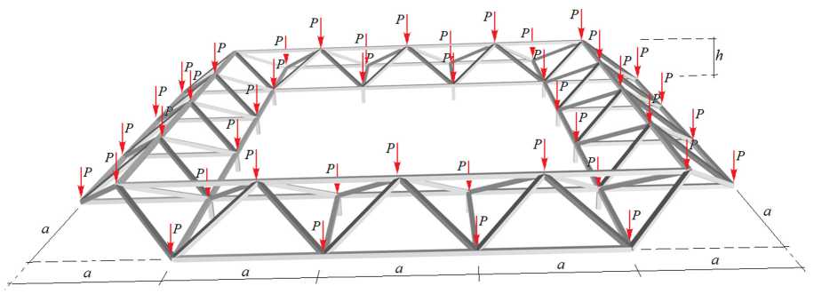
Fig. 1. The cover structure under uniform load n =5
-
2.2 Force Calculation Algorithm
Consider a uniform nodal vertical load applied to all truss nodes (Fig.1). The forces will be calculated in a program written in the Maple [28] language. To enter information about the structure of the structure into the program, the nodes are numbered (Fig. 2) and their coordinates are entered. In addition to the support nodes fixed on a fixed base, the truss contains 12 n - 16 nodes. The upper contour consists of 4( n - 1) rods, the rest in the lower contours. The coordinates, for example, of the lower external non-closed contour are:
-
x, = ai, y,. = 0, z, = 0, iii
xi+n-1 = an, У+ n-1 = ai, zi+n-1 = 0, xi+2n-2 = a(n - i), yi+2n-2 = an, zi+2n-2 = 0, xi+3n-3 = 0, yi+3n-3 = a(n - i)> zi+2n-3 = 0, i = ^"t n - 1
The coordinates of the nodes of the upper closed contour have the form:
xi+4n-4 = a(i - 1 /2), yi+4n-4 = a /2, zi+4n-4 = h, xi+5n-5 = a(n - a / 2), yi+5n-5 = a(i - 1/ 2), zi+5n-5 = h, xi+6n-6 = a(n - i + 1 /2), yi+6n-6 = a(n - 1 /2), zi+6n-6 = h, xi+7 n-7 = a/2, yi+7 n-7 = a (n - i + 1/2), zi+7 n-7 = h, i = 1,-, n " 1-

Fig. 2. Numbering of nodes and horizontal links n =5
The order of connection of the rods is set by special lists Фа = [ z '1, i 2] of numbers 1 1 , i 2 hinges at the ends of the rods a = 1,.., N . The bars of the lower outer contour has, for example, the following node numbers at the ends: Ф i + j ( n - 2) = [ i + j ( n - 1), i + j ( n - 1) + 1], i = 1,.., n - 1, j = 0,..,3. . The numbers of the remaining bars of the contours are set similarly. The choice of the initial and final end of the rod (the first or second component of the ordered list Фа = [ ivi 2] ) is arbitrary and is not related to the sign of the force in this rod.
The system of equilibrium equations of nodes in projections on the coordinate axes is considered in matrix form GS = B , where G is the matrix of projection equation coefficients, S is the vector of all forces and reactions of the supports, B is the load vector. The projections of the conditional vectors of the rods have the form L,. = хл - хл , I ,. = ym - ym , L,. = z№ - z_ . The matrix G of the system of x , ф 1 ,1 ф 1 ,2 y , i Ф i ,1 Ф i ,2 z , i Ф i ,1 ф 1 ,2
equilibrium equations is composed of the direction cosines of the forces. In this case, the force on one end of the rod and the other is applied in opposite directions, therefore, the direction cosines have different signs:
G^ ,.= l .1 l,G.m ,.= l .1L, G^ . = l .11,
3 Ф i I — 2, i x, i i , 3 Ф i I — 1, i y, i i , 3 Ф i । , i z , i i ,
G3Ф,2-2,i = -lxi I 4^3Ф,2-1,i = -^ / l, G3Ф.2,i = -1^ I l• where l = 7C + lyi + lz,i —
rod length. The solution of the system of equations is obtained in symbolic or numerical form.
3 Results and Discussion 3.1 Forces in rods
Consider the case of loading a truss with a uniform vertical nodal load. The load vector on the right side of the equilibrium equation system has the form B 3 i = — P , i = 1,..,12 n — 16. Figure 3 shows the distribution of forces in the structure bars. The force values are related to the load on node P and rounded to two significant figures.
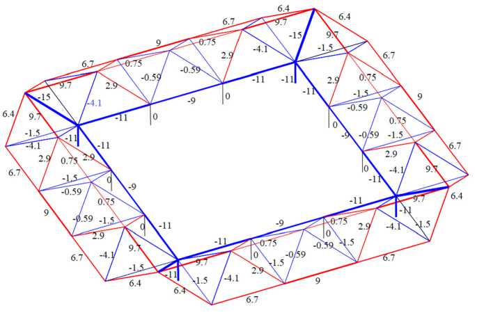
Fig. 3. Distribution of forces in the truss rods, n= 5 , a= 3 m , h= 1 m
Tensioned rods are highlighted in red, compressed rods are highlighted in blue. The thickness of the segments of the rods is conditionally proportional to the modules of the corresponding forces. Thin segments of black color are not tense. The reactions of the angular vertical supports are equal (3 n — 4) P , the remaining vertical posts and angular horizontal connections under such a load and for any number of panels n have zero forces. The most loaded inclined corner rods. The structure hangs on four compressed rods connected by the upper stretched contour of the rods. The lower inner contour is also compressed. In Figure 2, some rods are marked with letters, for which formulas will be found for the dependence of forces on the number of panels. Calculating forces in trusses with n = 4,5,6,... the following sequences of expressions are obtained:
D = — 5 Pc I (2 h ), — 13 Pc I (4 h ), — 4 Pc I h , — 19 Pc I (4 h ), — 11 Pc I (2 h ),...,
O 1 = — 5 Pa I (2 h ), — 13 Pa I (4 h ), — 4 Pa I h , — 19 Pa I (4 h ), — 19 Pa I (4 h ),...,
O 2 = Pa I h , Pa I (4 h ), — Pa I (2 h ), — 5 Pa I (4 h ), — 2 Pa I h ,...,
-
U , = 3 Pa I (2 h ), 9 Pa I (4 h ), 3 Pa I h , 15 Pa I (4 h ), 9 Pa I (2 h ),..., (1)
U 2 = 3 Pa I (2 h ), 3 Pa I h ,9 Pa I (2 h ),6 Pa I h ,15 Pa I (2 h ),...,
T 1 =— 3 Pa I h , — 15 Pa I (4 h ), — 9 Pa I (2 h ), — 21 Pa I (4 h ), — 6 Pa I h ,... .
can be found using the special operators rgf_findrecur and rsolve of the Maple system or, somewhat more simply, in the computer mathematics system Wolfram Mathematics operator FindSequenceFunction . This operator requires a smaller sequence length to obtain the general term formula and does not require, like the rsolve operator, to find a recursive equation that the terms of the sequence satisfy. We get the following linear dependencies on the number of panels:
D = - Pc (3 n - 2) / (4 h ), O1 = - Pa (3 n - 2) / (4 h ),
O2 = Pa (16 - 3 n ) / (4 h ), U 1 = 3 Pa ( n - 2) / (4 h ),
U 2 = 3 Pa ( n - 3)/(2 h ), T = 3 Pan /(4 h ).
These formulas can be used to calculate the critical loads on a structure as a function of the number of panels in terms of compressive strength and tensile strength of bars.
-
3.2 Deflection
When calculating the deflection at individual points of the truss, we will use the Maxwell-Mohr formula, assuming that all the rods are linearly elastic.
N
A = £ S a P ' S®l . I ( EF ) (2)
a= 1
The sum is compiled for all elastic bars of the structure, including bars that the model supports. The standard designations are used in the formula: EF is the rigidity of the rod, S a P ) is the force in the rod with a number a from the action of an external load, S a 1 is the force in the same rod from the action of a unit vertical force applied to the node whose deflection is measured, l a is the length of the rod.
As in the derivation of formulas for the dependence of forces in rods on the number of panels, we use the induction method. Let us consider the displacements of points on consoles along with one of the side edges of the structure. In the general case, these are nodes with numbers 1,..,( n - 1) along the lower outer contour (Fig. 2).
The derivation of formulas is carried out in two stages. First, we find the dependence of the deflection A 1( n ) at point 1 on the number of panels n . Sequential calculation of the deflection according to the formula (2) with b = h gives the formulas:
A 1 (3) = P (1984 a 3 + 19 c 3 + 160 h 3) / (32 h 2 EF ),
A 1 (4) = P (1088 a 3 + 7 c 3 + 64 h 3) / (8 h 2 EF ),
A 1(5) = P (6912 a 3 + 37 c 3 + 352 h 3)/(32 h 2 EF ),
A 1 (6) = P (4544 a 3 + 23 c 3 + 224 h 3) / (16 h 2 EF ),
A 1 (7) = P (10304 a 3 + 55 c 3 + 544 h 3) / (32 h 2 EF ),...
Generalizing these formulas by methods of the Maple system to an arbitrary number n :
A k ( n ) = P ( C1 a 3 + C 2 c 3 + C 3 h 3)/( h 2 EF ), (3)
where for k = 1 the coefficients have the form:
C1 = - 3 n 3 + 39 n 2 - 88 n + 56, C 2 = (9 n - 8) / 32, C 3 = 3 n - 4.
Similarly, we obtain dependencies for the deflections of other points A 2( n ), A 3( n ), A 4( n ),... on the lateral truss edge. In this case, the number of panels and the point number k must satisfy the inequality n > k + 1 , so that the point understudy does not go beyond the edge of length ( n - 1) a . We have the following expressions for the coefficients of formula (3):
k = 2: C 1 = 3 n 3 - 15 n 2 + 40 n - 4, C 2 = (21 n - 44)/32, k = 3: C 1 = 9 n 3 - 69 n 2 + 132 n + 136, C 2 = (33 n - 104)/32, k = 4: C 1 = 15 n 3 - 123 n 2 + 116 n + 836, C 2 = (45 n - 188)/32, k = 5: C 1 = 21 n 3 - 177 n 2 - 80 n + 2600, C 2 = (57 n - 296)/32,...
One coefficient, starting from k = 2, does not depend on the number of the point k at which the deflection is measured: C 3 = 8 n - 6 . Generalizing these expressions for k , we obtain the final expressions for the coefficients in the deflection formula (3):
C 1 = (3(2 k - 3) n 3 - 3(18 k - 31) n 2 - 2 n (6 k 3 - 27 k 2 - 25 k + 90) + 2(3 k 4 - 25 k 2 + 50)) /16,
C 2 =- (12 k 2 - 12 kn + 3 n - 4)/32,
C 3 = 6 n - 8, k > 1, C 3 = 3 n - 4, k = 1.
Let's introduce the value of the dimensionless deflection A ' , referred to the length of the lateral side of the truss L = ( n - 1) a and the total load P 0 = 4(3 n - 4) P : A ' = EF A k ( n )/( P 0 L ) . The found dependences of deflections at various lateral points on the console have a limiting value on the horizontal asymptote: lim A ' = (7 + 4 k ) h / (16 L ). n ^^
-
3.3 The natural frequency
The frequency of natural oscillations is one of the main dynamic characteristics of the structure. Most often, calculations require the first (lowest) frequency, the lower limit of which can be obtained for regular structures in analytical form depending on the number of panels [29].
To calculate the natural vibration frequencies of the structure under consideration, we will take a simplified but widely used truss model, placing the masses evenly over all nodes. We will assume only the vertical motions of nodes. Thus, the system has K = 12 n - 16 degrees of freedom. In symbolic form, for such a system, one can obtain a lower bound for the first frequency [29]. The Dunkerley formula [30] for the lower frequency limit has the form:
K
-
-2
toD = / , top .
p = 1
where to p are the partial frequencies. The equation of vertical oscillations of the mass m located in a separate node has the form:
mzp + Dpzp = 0, P=1--K-(5)
Here Dp — stiffness, the reciprocal of compliance 5 p = 1/dp . Compliance (vertical displacement) can be calculated using the Maxwell-Mohr formula:
N 2
8p = 1/ D, = £(S('') lj /(EF)■ j=1
where S ( j p ) is the force in the rod with number j from the action of a vertical unit force applied to the node where the mass is located. The stiffness factor and the partial frequency depend on the location where the mass is located. In the case of harmonic oscillations zp = U p sin( to t + ф ) , from (5) we obtain the partial frequency to p = ^ Dp / m . Substituting this expression into (4):
to D = m ]T 8 p = m A ( n ). (7)
p = 1
Calculations of the frequencies of trusses with a different number of panels show that the coefficient in (7) has the form:
A ( n ) = ( C 1 a 3 + C 2 c 3 + C 3 bh 2 ) / ( EFh 2 ( n - 1)( n - 2) ) (8)
А (3) = (136 a 3 + 33 c 3 + 456 h 3 )/ (8 EFh 2 ),
A (4) = (1352 a 3 + 205 c 3 + 2158 h 3) / (36 EFh 2),
A (5) = (11710 a 3 + 1215 c 3 + 11016 h 3)/(144 EFh 2),
A (6) = (6718 a 3 + 484 c 3 + 3829 h 3) / (40 EFh 2),
A (7) = (117136 a 3 + 5987 c 3 + 41720 h 3)/(360 EFh 2),...
Finding the common members of the sequences of coefficients at a 3 , c 3 , and h 3 , we obtain the dependences of the coefficients in (8) on the number of panels:
C 1 = (8 n 6 - 88 n 5 + 473 n 4 - 1300 n 3 + 1861 n 2 - 1318 n + 360)/24,
C 2 = (5 n 4 - 25 n 3 + 62 n 2 - 73 n + 30)/12, (9)
C 3 = 2(4 n - 3)(8 n 3 - 48 n 2 + 104 n - 77) / (3( n - 2)).
Thus, formula (7) with coefficients (9) gives an analytical expression for the dependence of the estimate of the first natural oscillation frequency of the truss on its dimensions and the number of panels. The degree of error of such an estimate can be estimated by comparing it with the first frequency of the entire spectrum of natural frequencies of the structure obtained numerically. This solution reduces to an eigenvalue problem. The system of differential equations of motion of the masses of a structure with K number of degrees of freedom is written in matrix form:
m I K Z + D K Z = 0, (10)
where D K is the stiffness matrix, Z is the vector of all vertical mass displacements in the truss nodes, Z is the acceleration vector, I K is the identity matrix. Multiplying (10) from the left by the matrix B K inverse to D K , we obtain the equation:
m B K Z + 1 K Z = 0. (11)
For harmonic oscillations with the frequency to we have a connection Z = -to 2 Z . It follows from (11) that B K Z = X Z , where X = 1/ ( to 2 m ) are the eigenvalues of the matrix B K . The elements of this matrix are calculated using the Maxwell-Mohr formula:
b ,- = NL^i(i)Sjк /(EF). i, j a a a a=1
Matrix eigenvalues can be determined numerically in the Maple system using the Eigenvalues operator with the linear algebra package LinearAlgebra connected.
Consider a steel truss with masses m = 150kg in nodes. Let's take EF = 2.0 - 104kN the rigidity of the rods, the dimensions of the panels а = 3.0m, h = 1.0m, the height of the racks b = 3.0m. Figure 4 shows the dependences of the first frequency on the number of panels, obtained numerically and analytically.
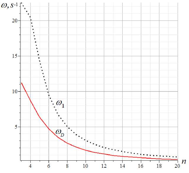
Fig. 4. Comparison of the first frequency m. and its lower analytical estimate m D
With an increase in the number of panels, the curves converge, but analysis of the relative error s = ( m . - m D )/ m . (Fig. 5) shows that this value has a minimum.
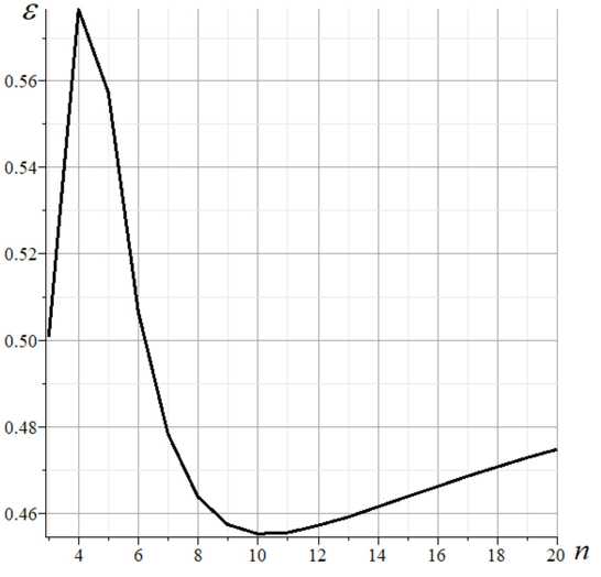
Fig. 5. The error of the analytical solution for natural frequency depends on the number of panels
-
3.4 Discussion
In the process of choosing a closed-loop spatial truss scheme, various options were considered. Statically indeterminate circuits were not seen as unrealistically difficult for analytical methods. In many cases, when designing a suitable circuit, it was necessary to add various support rods, asymmetrically located on the sides of the structure. Such schemes, although sometimes quite simple, had to be abandoned. The goal was a scheme that had not only static determinate but also perfect symmetry. In addition, the number of rods of different lengths number should have been minimal. Such a scheme has been created. As an unexpected positive feature, the design also received a cantilevered contour on all four sides. When developing the scheme, the complexity of analytical calculations was not discussed. Despite this, the obtained scheme, as it turned out, has fairly simple analytical solutions for both the deflections and the lower estimate of the first natural frequency. When deriving formulas for the deflection, the method of double induction, which is quite time-consuming in terms of calculation, was used. One induction parameter is the point number on the console, the second is the number of panels. The use of Wolfram Mathematica system operators for finding common terms of sequences of coefficients of the desired formulas turned out to be a significant help. Analytical solutions are not only compact, convenient for calculations, and can be applied without loss of computational accuracy for systems with a very large number of rods, but also give asymptotic estimates. For deflections, the asymptotics for the number of panels turned out to be linear both for the number of panels and for the number of the point on the console where the deflection is measured.
The proposed scheme and the resulting calculation formulas can be considered as some basis for more complex, in particular, statically indeterminate structures or structures that have an overlap of the internal space formed by the gallery. Without much difficulty, the solution for deflection and vibration frequency can be generalized to rods of various stiffnesses.
4 Conclusion
A new scheme of the asymmetrical statically determinate spatial structure of the cover is proposed and analytical dependences of its stress-strain state and oscillation frequency on the number of panels are obtained. The calculated formulas found are quite universal and can be applied to a wide class of such structures. The algorithm used in the derivation allows simple recalculation of the problem for other types of loads. The dependence of the lowest oscillation frequency on the structure order (number of panels) is obtained numerically. The analytical estimate gives little accuracy compared to similar estimates of the first natural frequency for planar trusses. The main result of the work is the design of the structure and the analytical dependence of some characteristics of its stress-strain state on the number of panels. Such solutions make it possible to analyze and select the most optimal parameters of the structure being designed without using a numerical solution. One of the advantages of the analytical solution is the independence of its accuracy from the complexity of the design. In three-dimensional problems requiring volumetric calculations, this advantage is more pronounced than for planar systems.
5 Acknowledgements
This work was financially supported by the Russian Science Foundation 22-21-00473.
Список литературы Частота деформаций и колебаний пространственной конструкции покрытия типа прямоугольного контура: аналитические решения
- Kumar, R., Sahoo, D.R. Seismic fragility of steel special truss moment frames with multiple ductile vierendeel panels. Soil Dynamics and Earthquake Engineering. 2021. 143. Pp. 106603. DOI:10.1016/j.soildyn.2021.106603.
- Chen, Z., Chen, F., Zhou, L. Slow-fast dynamics in the truss core sandwich plate under excitations with high and low frequencies. Applied Mathematical Modelling. 2020. 88. Pp. 382–395. DOI:10.1016/j.apm.2020.06.055.
- Liu, M., Cao, D., Zhu, D. Coupled vibration analysis for equivalent dynamic model of the space antenna truss. Applied Mathematical Modelling. 2021. 89. Pp. 285–298. DOI:10.1016/j.apm.2020.07.013.
- Santana, M.V.B., Gonçalves, P.B., Silveira, R.A.M. Closed-form solutions for the symmetric nonlinear free oscillations of pyramidal trusses. Physica D: Nonlinear Phenomena. 2021. 417. Pp. 132814. DOI:10.1016/j.physd.2020.132814.
- Abdikarimov, R., Vatin, N., Normuminov, B., Khodzhaev, D. Vibrations of a viscoelastic isotropic plate under periodic load without considering the tangential forces of inertia. Journal of Physics: Conference Series. 2021. 1928(1). DOI:10.1088/1742-6596/1928/1/012037.
- Han, Q.H., Xu, Y., Lu, Y., Xu, J., Zhao, Q.H. Failure mechanism of steel arch trusses: Shaking table testing and FEM analysis. Engineering Structures. 2015. 82. Pp. 186–198. DOI:10.1016/j.engstruct.2014.10.013. URL: http://dx.doi.org/10.1016/j.engstruct.2014.10.013.
- Ovsyannikova, V.M. Dependence of deformations of a trapezous truss beam on the number of panels. Structural Mechanics and Structures. 2020. 26(3). Pp. 13–20. URL: https://www.elibrary.ru/item.asp?id=44110286 (date of application: 11.03.2021).
- Ovsyannikova, V.M. Dependence of the deflection of a planar external statically undeterminable truss on the number of panels. Structural Mechanics and Structures. 2020. 27(4). Pp. 16–25. URL: https://www.elibrary.ru/download/elibrary_44374443_62905709.pdf.
- Ilyushin, A.S. The formula for calculating the deflection of a compound externally statically indeterminate frame. Structural mechanics and structures. 2019. 22(3). Pp. 29–38. URL: https://elibrary.ru/item.asp?id=41201106 (date of application: 27.02.2021).
- Rybakov, L. S., Mishustin, I. V. Small elastic vibrations of planar trusses of orthogonal structure. Mechanics of composite materials and structures. 2003. 9(1). Pp. 42–58. URL: https://elibrary.ru/item.asp?id=11724233 (date of application: 5.07.2021).
- Goloskokov, D.P., Matrosov, A. V. Approximate analytical approach in analyzing an orthotropic rectangular plate with a crack. Materials Physics and Mechanics. 2018. 36(1). Pp. 137–141. DOI:10.18720/MPM.3612018_15.
- Matrosov, A. V. Computational Peculiarities of the Method of Initial Functions. Lecture Notes in Computer Science (including subseries Lecture Notes in Artificial Intelligence and Lecture Notes in Bioinformatics). 2019. 11619 LNCS. Pp. 37–51. DOI:10.1007/978-3-030-24289-3_4.
- Galileev, S.M., Matrosov, A. V. Method of initial functions: Stable algorithms in the analysis of thick laminated composite structures. Composite Structures. 1997. 39(3–4). Pp. 255–262. DOI:10.1016/S0263-8223(97)00108-6.
- Hutchinson, R.G., Fleck, N.A. Microarchitectured cellular solids - The hunt for statically determinate periodic trusses. ZAMM Zeitschrift fur Angewandte Mathematik und Mechanik. 2005. 85(9). Pp. 607–617. DOI:10.1002/zamm.200410208.
- Hutchinson, R.G., Fleck, N.A. The structural performance of the periodic truss. Journal of the Mechanics and Physics of Solids. 2006. 54(4). Pp. 756–782. DOI:10.1016/j.jmps.2005.10.008.
- Zotos, K. Performance comparison of Maple and Mathematica. Applied Mathematics and Computation. 2007. 188(2). Pp. 1426–1429. DOI:10.1016/j.amc.2006.11.008.
- Kirsanov, M. Planar Trusses: Schemes and Formulas. Cambridge Scholars Publishing Lady Stephenson Library. Newcastle upon Tyne, GB, 2019.
- Kirsanov, M. Trussed Frames and Arches: Schemes and Formulas. Cambridge Scholars Publishing Lady Stephenson Library. Newcastle upon Tyne, GB, 2020.
- Voropay, R. A., Domanov, E. V. The dependence of the deflection of a planar beam truss with a complex lattice on the number of panels in the system Maple. Postulat. 2019. (1).
- Dai, Q. Analytical Dependence of Planar Truss Deformations on the Number of Panels. AlfaBuild. 2021. 17. Pp. 1701. DOI:10.34910/ALF.17.1.
- Voropay, R., Domanov, E. Analytical solution of the problem of shifting a movable support of a truss of arch type in the Maple system. Postulat. 2019. 1. URL: http://vuz.exponenta.ru/1/vd.pdf (date of application: 27.02.2021).
- Kazmiruk, I.Y. On the arch truss deformation under the action of lateral load. Science Almanac. 2016. 17(3–3). Pp. 75–78. DOI:10.17117/na.2016.03.03.075. URL: http://ucom.ru/doc/na.2016.03.03.075.pdf (date of application: 9.05.2021).
- Rakhmatulina, A.R., Smirnova, A.A. The dependence of the deflection of the arched truss loaded on the upper belt, on the number of panels. Science Almanace. 2017. 28(2–3). Pp. 268–271. DOI:10.17117/na.2017.02.03.268. URL: http://ucom.ru/doc/na.2017.02.03.268.pdf (date of application: 9.05.2021).
- Belyankin, N.A.; Boyko, A.Y. Formula for deflection of a girder with an arbitrary number of panels under the uniform load. Structural Mechanics and Structures. 2019. 1(20). Pp. 21–29. URL: https://www.elibrary.ru/download/elibrary_37105069_21945931.pdf.
- Kirsanov, M.N. Spectrum of own frequencies of a spatial surfacing girder. Russian Journal of Building Construction and Architecture. 2021. (3(51)). Pp. 104–113. DOI:10.36622/VSTU.2021.51.3.009.
- Vorobev, O.V. Bilateral Analytical Estimation of the First Frequency of a Plane Truss. Construction of Unique Buildings and Structures. 2020. 92(7). Pp. 9204–9204. DOI:10.18720/CUBS.92.4. URL: https://unistroy.spbstu.ru/article/2020.92.4 (date of application: 17.04.2021).
- Petrenko, V.F. The natural frequency of a two-span truss. AlfaBuild. 2021. (20). Pp. 2001. DOI:10.34910/ALF.20.1.
- Buka-Vaivade, K., Kirsanov, M.N., Serdjuks, D.O. Calculation of deformations of a cantileverframe planar truss model with an arbitrary number of panels. Vestnik MGSU. 2020. (4). Pp. 510–517. DOI:10.22227/1997-0935.2020.4.510-517.
- Vorobyev, O. About methods of obtaining analytical solution for eigenfrequencies problem of trusses. Structural mechanics and structures. 2020. 1(24). Pp. 25–38. URL: http://vuz.exponenta.ru/PDF/NAUKA/elibrary_42591122_21834695.pdf.
- Levy, C. An iterative technique based on the Dunkerley method for determining the natural frequencies of vibrating systems. Journal of Sound and Vibration. 1991. 150(1). Pp. 111–118. DOI:10.1016/0022-460X(91)90405-9.
