Common dataware of a proprioceptive robot control system

Author: Smirnov Yu.S., Yurasova E.V., Safronov V.V.
Journal: Вестник Южно-Уральского государственного университета. Серия: Энергетика @vestnik-susu-power
Section: Устройства аналоговой и цифровой электроники
Article in issue: 3 т.16, 2016.
Free access
The paper is devoted to the peculiarities of the Common Dataware for a significant part of manipulation robots. They have only a proprioceptive feedback system supplying information about position of “arms” and “hands” segments in joints. It outlines disadvantages of the Common Dataware generation based on incremental transducers and sensorless structures. Major parameters that determinate indicators of energy informational practice providing energy conversion into functional displacement of the robot working gear are revealed. The use of a resolver as a primary sensor is recommended, as it has the best noise immunity, shock, vibrations and temperature change resistance compared to other sensors. The “Resolver-to-Digital-Converter (RDC)”combination realizing the time and space binding corresponds to the general relativity postulate. A significant advantage of the proposed RDC solutions is a synthesis of digital equivalents of displacement components, which is implemented without a systematic error based on rigorous trigonometric algorithms. They provide resolution up to 20 bits in a range of 360° at its quadrantal or octantal split.
Common dateware, proprioceptive control system, manipulation robot, incremental sensors, sensorless structures, electromechatronic conversions, import substitution
Short address: https://sciup.org/147158367
IDR: 147158367
Единое информационное обеспечение проприоцептивной системы управления роботом
Работа посвящена особенностям единого информационного обеспечения (Common Dataware) значительной части роботов-манипуляторов. Они обладают лишь проприоцептивной системой обратной связи, которая формирует информацию о положении звеньев «рук» и «кистей» в шарнирах. Отмечены недостатки формирования Common Dataware на основе инкрементальных датчиков и бессенсорных структур. Выявлены важнейшие параметры, определяющие показатели энергоинформатики обеспечения процесса преобразования энергии в функциональное перемещение рабочего механизма робота. Рекомендовано в качестве первичного сенсора применение resolvers, имеющего лучшую из всех датчиков помехоустойчивость, стойкость к ударам, вибрациям и изменениям температуры окружающей среды. Комплекс «Resolver-to-Digital-Converter», реализующий связь пространства и времени, соответствует постулату общей теории относительности. Важным достоинством рассмотренных построений RDC является то, что синтез цифровых эквивалентов составляющих перемещения осуществляется без методической погрешности на основе тригонометрических алгоритмов. В перспективе они обеспечат разрешение до 20 бит в диапазоне от 360° при квадрантном или октантном его разбиении.
Text of the scientific article Common dataware of a proprioceptive robot control system
Modern mechatronics derived from electronics and engineering cybernetics inherits a number of scientifically and practically based algorithms and methods of energy conversion into a functional displacement of the working mechanism. It is an integral part of the most machines and units. Mechatronics has found the largest application in robotics, where it replaces a muscle force.
For adaptation, self-organization, optimization, invariability under internal and external disturbances of a mechatronic system, reliable data on components of displacement are needed: its value Θ, speed Ω and acceleration ε (Fig. 1) [1].
To enable a continuous-path robot guidance (i.e. to carry out a rather complex movement with a variable speed instead of following a short “from A to B” route), controls shall include sensors that monitor not
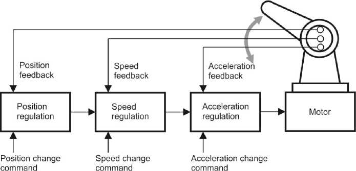
Fig. 1. A proprioceptive feedback circuit
only position of each of manipulator segment, but also speed of manipulator movement, whether it accelerates or delays. Such feedback information and responses circulate within several closed loops. As far as each sensor supplies data, “circuits in circuits” are formed. The complexity of such system becomes obvious if one considers that such control loops are required for each of six (or more) robot joints and an additional control level is needed for coordination of the whole structure operation [2].
Essence of feedback concept
Since the feedback concept plays a key role in any autonomous system, such as a robotic machine, it is necessary to understand its essence clearly. The main idea is that the function of a control (robot computer) must include not only instruction generation and transfer (as electric signals supplied to the motor), but also perception and interpretation of feedback data reflecting execution status of these instructions and their impact.
Proprioceptive control system
Its development is quite simple as any condition it will have to deal with can be set and even forecast: robot link controlled by sensors will never be placed in a position that cannot be forecast by the developer provided the robot is functioning correctly. The computer receiving data from various sensors should only process data on a limited number of strictly defined conditions. The accuracy and effectiveness of the control is achieved because information circulates in a closed circuit – commands to perform certain actions are generated while feedback, which is the second part of the circuit, supplies data reflecting results of these operations. Most modern robots have only a proprioceptive feedback system providing with information on the position of the links of “arms” and “hands” in the joints. Proprioceptive sense organs are important for all robotic machines except the simplest ones
(sometimes called “loaders”), motions of which can be limited and directed with the use of mechanical stops, or limit switches [1].
A robot controlled by the program (set in the computer) rather than by hardware requires a proprioceptive system and feedback realized by it, as it is impossible to provide conditions with absolute results at program repetitive run. There are some “noises” or random jamming within any electrical system; thus, if the robot has no feedback to enable its control, once getting out of time, the robot will not be able to get with it.
Encoders are widely used for supply of feedback signals on the position of robot limbs (Fig. 2).
Fig. 2 shows two types of optical encoders used to control the position of manipulation robot links and supply feedback signals, which are necessary for an appropriate robot control. The sequence of transparent and opaque cells in the rings forming a code disk is “read” by photocells. As a result, the binary code is formed (opaque cell – 1; transparent – 0), which displays a current position of the rotating shaft and is supplied to the robot control computer as feedback signals. The more rings the disk has (accordingly, the more “coding” bits a message includes), the higher an overall accuracy of position finding is. The angle-to-digit converter is presented as a single unit with the robot joint (Fig. 2a) for descriptive reasons; in fact, it is a self-contained device (Fig. 2b), which is mounted on one of shaft ends or on the outer side of the motor.
Digital equivalents of speed Ω and acceleration ε of displacement in the system shall be formed by the computer. In some cases, this is not an optimal way in terms of the noise immunity. It may result in decrease of supply of reliable speed Ω and acceleration ε data at low rotation frequencies, which deteriorates smooth movements of the robot.
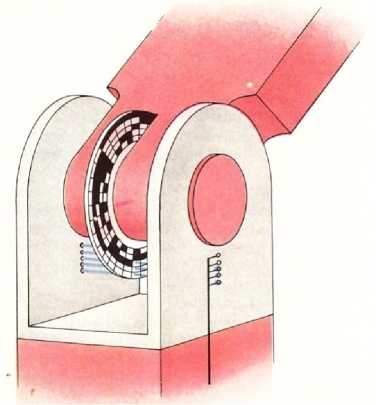
a)
Fig. 2. Types of encoders: built-in (a), autonomous (b)
b)
Major indicators of robot movement
The point at issue is about a strict compliance of trajectory of the robotic arm (or working body) with a new program activated and of its further movements provided by this program. Repeatability of a half millimeter and even lower is sufficient for large facilities used, e.g. at spot welding. However, this indicator amounts several micrometers for smaller robots recently developed for precision instrument and tool (e.g. watches) manufacturers.
Different operations are carried with different speeds: for example, the robot carrying out spray painting has apparently to change the rate to provide a uniform paint layer, while movements of the robot carrying over crucibles with molten metal must be pull-free. Thus, the robot control system must probably be quite difficult and consist of several feedback loops with their own feedbacks. Besides, each manipulator segment (i.e. each degree of freedom) should be equipped with a separate set of sensors and feedback loops, and the computer controlling the robot as a system must provide coherence of all manipulator joints. In particular, it is possible due to transferring some decision-making functions to individual microprocessing units receiving and processing feedback signals from one or more joints under control of the central robot computer, thus, providing their movement in accordance with the program.
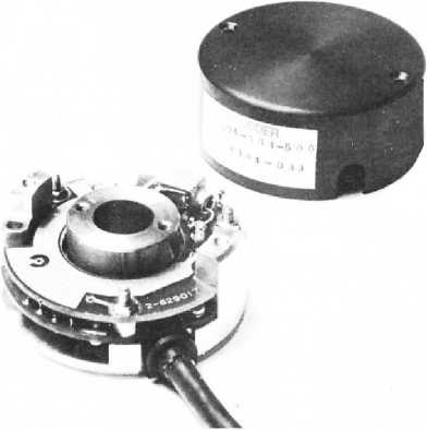
Fragile objects (Fig. 3) such as test tubes and bulbs with radioactive substance during radioactive incident and accident remedial operations shall be handled with a high sensitivity. Damage of bulbs with radioactive substances will result in the need for decontamination of fixed-site and mobile laboratories, disposal of contaminated equipment, furniture and vehicles [3].
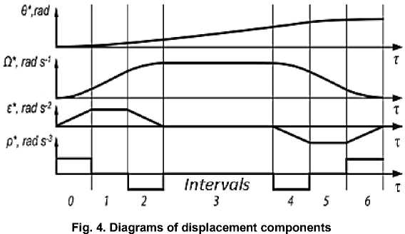
It may also be necessary to define the rate of acceleration or deceleration rather than the speed of the manipulator movement itself. This is because the freight and the loaded manipulator have an inertia lag, and their motion pattern depends on the moment of exerted forces. Robotic arm must not “rotate” like an arm of a boxer in the ring: it will function effectively at a gradual acceleration and soft controlled stop as it approaches to the target point only. Such operating conditions of the robotic gripper (Fig. 3) are implemented at a profile control [4–7]. Fig. 4 shows profiles (trajectories) of setting the position Θ*, speed Ω*, acceleration e and an acceleration signal - jump p .
Researches carried out in [5] show that:
@ * = 0 k +Q k ( t-t k ) + 0,5 s k ( t - t k ) 2 + p k ( t - t k ) 3/ 6;
Q * = Q k +s k ( t-t k ) + 0,5 p k ( t-t k ) 2; s * = s k +p k ( t-t k ) , where p k = d s / d t ; t k - is a time of start of k interval of a constant jump p k .
Unfortunately, incremental encoders not providing a stable accuracy of positioning data support are widely used in a modern mechatronics. A “sensorless” [7, 8] data support of the electric drive is usual, which can be used in the above simple manipulators [1] only. It should be noted that the use of digital incremental encoders in the close-control electrical-drive systems [5, 6] and mechatronics is limited. “Loss” of position and displacement information at power failures is a great disadvantage of such encoders. Therefore, every time the device is turned on it should to be moved to an initial (datum) point of the sensor initiated within a separate measuring circuit. The use of such encoders causes certain difficulties in the movement control dynamics at 50–100 ms sampling period of digital control [5].
State-of-the-art. Development of mechatronics has led to a significant increase of requirements to energoinformatics [9] in terms of its functionality. They allow solving tasks successfully by following the precepts of scientific predecessors and using achievements of information technology. A minimum design strategy required the electronification of EMTC structure and its information support. At the present stage, it has led to the use of a direct electric drive based on contact free electric machines with permanent magnets of rare-earth alloys. Initially, control of these electric machines required the use of a special rotor position sensor for supply of “auto-phased” control signals by electronic power invertors.
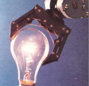
Fig. 3.Robot gripper
A sensor locating an absolute position of the working body within the whole movement range with a high reliability was needed to provide adaptation properties of the mechatronic system or its highest level. Optimization of relocation in time required speed feedback implemented by the DC or AC tachometer. A robust, modal and profile control is possible through the acceleration feedback loop ε (see Fig. 1), for example, using an acceleration transducer. Its significant drawback is a speed error. In the long term, it may be limited by means of a promising device based on the effect of a nuclear magnetic resonance valued by 0.0001 degree per hour [10].
The proposed solutions do not have this drawback as an inverse order of the formation of components is used according to the general relativity theory; it includes differentiating the value of displacement not in the forward loop of component converting, but in the feedback loop by a double integrating acceleration [11–13]. Thus, increase of noises at error signal differentiating may be prevented. The use of a statistical link in the feedback loop promotes a further improvement of noise immunity and accuracy of precision RDCs. Its idea differs from the Kalman filter, while it allows generating a current value of the control error in the real time mode with the mathematical regression analysis. Thus, the impact of random signal fluctuations signals in the conversion feedback loop the on the error is eliminated [14].
Nowadays, the Resolver-to-Digital Converter (RDC) is a component that complies with requirements of mechatronics energoinformatics [5] to a full extend. Preference is given to resolvers enabling a space-time binding together with the microelectronic Resolver-to-Digital-Converter [15], i.e. that with chronotope properties. Digital equivalents of displacement components are generated without a systematic error through rigorous trigonometric algorithms of sine-cosine, tangent-cotangent and arctangent functions [5]. A common dataware [2] simplifies electrical engineering of the system and provides a formation of digital equivalents with the resolution up to 20 bits within the range of 360°.
Operational method of synthesis of differential control algorithms
Its practical importance is in the possibility to develop serial and parallel control algorithms. This method has been time-tested during development of tracking systems. It enables compact digital algorithms and real time programs based on microprocessors with RISC architecture, and development of multicomponent and multifunctional converters. The scientific and practical outcome can be used in mechatronics, robotics, engineering cybernetics, and at practical development of the servo drives [14]. Application of this method increases effectiveness of the common dataware based on the amplitude and phase converters [11].
As a result, the following tasks were solved:
-
1. The operation algorithm of the tracking convertor with the more “intelligent” regressive statistical
-
2. The algorithm for the digital angle converter with a saw-tooth current excitation of the resolver and mathematical regressive model in the feedback loop was synthesized. The converter is a closed-loop servo system for each of two output sensor windings.
-
3. The proposed method enables conversion speed increase due to the use of the synthesized parallel algorithm, which can be realized by a parallel operation of several RISC microprocessors.
link in the feedback loop was developed in order to improve the accuracy of its measurements.
System synthesis is performed in four steps:
-
– selection of the structure as a set of minor control loops;
-
– type definition for transfer functions of each control loop based on results of analyses of the Bode magnitude diagram and phase frequency diagram influence on the stability of the total system;
-
– conversion of the Laplace representations of transfer functions into the Cauchy differential equation system;
-
– development of algorithms for solving the differential equation system; selection of hardware and software tools for project realization.
While the first two mentioned steps are heuristic, the latter three, vice versa, are determined and may be realized by the proposed mathematical operational method of synthesis of the differential control algorithms for digital servo systems.
The scientific novelty of the proposed operational method [14] is in the conversion of the converter’s linear differential equation system into that of the mathematical model difference equations. An important feature of this method is the possibility to convert both linear differential equations and their operational Laplace representations into differential algebraic equations by the replacing derivatives in the transfer function.
Principle of operational method: there are so-called “left” and “right” differences of the function in algebra. In contrast with “right” differences, which play an important role in mathematical analysis, “left” differences are used in the proposed operational method of conversion of differential equations into a differential form. They represent the difference between the value of the function in a current time ( t ) and the value in the “past” time ( t – dt ). Thus, if the function f ( t ) is set, its value in the past time can be written as follows: f ( t – dt )= f ( t )∙ E. Here E – is a formal operator of the shift. This formula should be read as follows: apply the operator Е (symbolized with a multiplication sign) to the function f ( t ) once . Thus, this operator applied to the function in a current time allows a formal recording the function value in a preceding (past) time.
It is proved that it is necessary to replace derivatives (y)k or operators (p)k, which have a k-order, by corresponding expressions of the form (1 - E)k ∆tk to enable conversion of linear differential equations or their operational Laplace representations into difference algebraic equations with the proposed operational Е-method. E-operator of “multiplication” and “addition” forms a binary algebra for a set of real numbers, that is, the Abelian (commutative) group possessing following features:
-
I. Features of shift operator:
-
1. c∙E = c , i.e. the constant is invariant to time shifts;
-
2. f ( t ) = f ( t )∙ E 0 , from which 1∙ E 0 ≡ 1, i.e. there is a multiplicative unit element;
-
3. f ( t – dt ) = ( f ( t ) + 0)∙ E = f ( t )∙ E + 0∙ E , from
which 0∙ E 0 ≡ 0, i.e. there is an adding zero element;
-
II. Commutative laws:
-
4. ( f ( t ) + φ( t ))∙ E = (φ( t ) + f ( t ))∙ E , for “addition”;
-
5. ( f ( t )∙φ( t ))∙ E = ( φ ( t )∙ f ( t ))∙ E , for “multiplication”;
-
III. Distributive laws:
-
6. ( f ( t ) + φ( t ))∙ E = f ( t )∙ E + φ( t )∙ E , for “addition”;
-
7. ( f ( t )∙φ( t ))∙ E = ( f ( t )∙ E )∙(φ( t )∙ E ), for “multiplication”;
Reading these expressions in the right-to-left direction is also true and gives associative “adding” and “multiplication” laws. Moreover:
-
IV. N-foldapplication ofoperator to function:
-
8. f ( t – dt ) = f ( t )∙ E ;
-
9. f ( t – 2 dt ) = f ( t – dt )∙ E = f ( t )∙ E 2 ;
-
10. f ( t – ndt ) = f ( t – ( n – 1) dt )∙ E =
= f ( t – ( n – 2) dt )∙ E ∙ E = … = f ( t )∙ En .
-
V. Differentiationrules:
-
11. df ( t ) dt = lim ∆ t → 0 ( f ( t ) - f ( t -∆ t )) ∆ t =
-
12. dnf ( t ) dtn = f ( t )(1 - E ) n dtn , where (1 - E ) n – a polynomial, it can be expanded in the Maclaurain's series or by the binomial formula.
= f ( t )(1 - E ) dt .
Here, dt – “time quantum” (it should be sufficiently small);
The introduced notion dt (time quantum) is connected with the necessity of a quantization of the continuous function for its representation in a lattice (discrete) form. The value of the quantum dt is selected substantially smaller than any time constant of the studied process.
-
VI. Remarks toprogram implementation:
-
1. To implement formulas of synthesized algorithms, an inexpensive microprocessor with the RISC-architecture can be used.
-
2. Global variables, such as “ real ” – a real number – are stored in the register, and the “ array of real ” variable (an array of two real numbers addressed by a shift indicator) is stored in two registers, which are series-connected and being a “push-down stack”.
-
3. It is to be recalled that all coefficients are numeric constants calculated in during programming before the firmware upgrade into a flash -memory.
Models of self-organizing tracking RDCs
Two variants of the realization of the selforganization of a tracking RDC are proposed as an illustration of the potential of the method:
-
– adaptation of the “second kind” realized by varying with a numerical pole value;
-
– adaptation of the “third kind” implemented by rebuilding the structure due to an alternative pole changing in the transfer function.
-
Fi g. 5 shows an adaptive algorithm of a “second kind” realized by varying the numerical pole value.
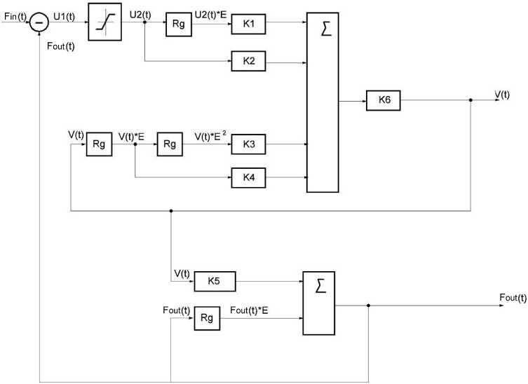
Fig.5. Adaptive algorithm of “second kind” realized by varying the pole numerical, where:
K 1 = kT 1 /At ; K 2 = k (1 + T 1 /At ); K 3 = T 2 T 31 At 2; K 4 = ( T 2 + T 3)/ At + 2 T 2 T 3 ] At 2; K 6 = 1/(1 + ( T 2 + T 3)/ At + T 2 T 3 / At 2)
-
Fi g. 6 provides an adaptive algorithm of the “third kind” implemented by changing structural elements of the algorithm.
The synthesized models of adaptive algorithms of the “second” and the “third” kinds allow a purposeful influence on dynamics of the electronic servo system with the servo-system type number of the second order. The decision to change the algorithm of conversion is made by RDC itself by changing the frequency the Bode magnitude diagram from the minimum to the maximum cutoff frequency [11].
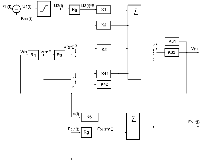
Fig. 6. Adaptive algorithm of “third kind” implemented by changing of structural elements of the algorithm, where: K1, K2, K3, K41 = K4, K5, K61 = K6 - are the same as in Fig. 5; and K 42 = T 2/A t ; K 62 = 1/(1 + T 2/A t )
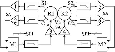
Fig. 7. Diagram of mating М1 and М2 digital modules of RDS–M microcircuit with R1 and R2 resolvers of two-speed conversion system
Table 1
Comparison of characteristics of RDS–M microcircuit with analogs produced by USA companies: DDC, Analog Devices, AeroFlex [14]
|
Parameter |
RDS-M |
RD-19230 |
AD2S1210 |
ACT5028 |
|
Power supply, V |
Single-supply, 4,25±1,25 |
Dual-supply, ±5 |
Single-supply, 5±0,25 |
Single-supply, 5±0,25 |
|
Consumptioncurrent, mA |
40 |
25 |
35 |
20 |
|
Referencefrequency, Hz |
0…30,000 |
0…10,000 |
3,000…20,000 |
45…30,000 |
|
Maximum rotation velocity, rpm |
0…5,000 |
0…1,152 |
0…3,125 |
0…1,024 |
|
Maximum precision, bits |
12…16 |
12…16 |
12…16 |
12…16 |
|
Signalbandwidth, Hz |
25…6,400 |
300...1,200 |
125...6,500 |
2…7,500 |
|
Method of the implementation of algorithm |
Digital |
Analog |
Digital |
Analog |
|
Number of channels in the casing |
2 |
1 |
1 |
1 |
Domestic equivalent of RDCs
It is worth to mention an outstanding Russian dual-channel equivalent of the RDC–M microcircuit with M1 and М2 digital modules mated with R1 and R2 resolvers through the low-pass filters and SA1–SA6 scaling amplifiers; see the diagram in Fig. 7.
Comparison of characteristics of the RDS–M microcircuit with foreign analogs is given in Table 1. Metrological parameters of the microcircuit are comparable with those of the best foreign analogs. Unfortunately, its functionality in terms of formation of a digital equivalent of the component of the displacement velocity Ω [12, 13] is still an area for further development activities.
Conclusion
It is important to note that recent achievements at development of absolute kinesthetic sensors or optical and magnetic generating encoders [16] fits well into proposed variants of an uniform phase and amplitude data support design [11]. The common disadvantage of foreign and domestic RDCs presented in the table is the lack of digital equivalents of acceleration ε and orthogonal components representing “auto-phased” electric drive control signals. This additional data will provide their multicomponent [17] or multifunctional [2] nature. At the same time, the solution [18] representing the option of the integrated formation of digital equivalents of displacement and its orthogonal components becomes highly important. The formation of the acceleration digital equivalent enables RDC self-organization. Thus, a dynamic error of the conversion may be reduced due to the change of the algorithm of the error signal transformation. The time of RDC output codes setting is decreased by two orders at step change of the input signal [11]. The energoin-formatics development level obtained provides RDCs with the artificial intelligence, adaptation and selforganization, time optimization, invariance to internal and external disturbances at the profile control [4–6]. The multicomponent and multifunctional converters using kinesthetic and generating [16] sensors of any physical nature with chronotope properties at the common dataware [5] are subject to the time-space binding postulate formulated in the Einstein’s general relativity theory in 1916 [19]. Dimensions of components shown in Fig. 4, which are nothing but the traveldependent time derivatives, are clear examples of this notion. Modern microelectronics facilitates implementation of a robust [13] and module [20] control with a new algorithmic and structural support, for which development modern method of synthesis [21–22] are needed.
The authors appreciate the Bachelor of Linguistics Mironova A.S. for the help in translation.
References Common dataware of a proprioceptive robot control system
- Не счесть у робота профессий/П. Марш и др.; пер. с англ. Ю.А. Кузьмина.; под ред. д-ра мед. наук, проф. В.С. Гурфинкеля. -М.: Мир, 1987. -182 с.
- Smirnov, Y.S. Common Dateware of Robotics Mechatronic Converters/Y.S. Smirnov//Proc. of the Third ISMCR’93, Torino, Italy. -1993. -P. 13-18.
- Smirnov, Y.S. Information Technologies and Robotics for Radioecological Training of Agro-Engineers/Y.S. Smirnov, I.V. Voinov, A.V. Choundeev//5th Conference on environmental education, Zurich, Switzerland. -1999. -P. 97.
- Drury, B. The Control Techniques Drives and Controls Handbook/B. Drury. -2nd Edition. -The Institution of Engineering and Technology Publ., London, United Kingdom, 2009. -768 p.
- Балковой, А.П. Прецизионный электропривод с вентильными двигателями/А.П. Балковой, В.К. Цаценкин. -М.: Издат. дом МЭИ, 2010. -328 с.
- Balkovoi, A.P. Low Cost RDC/A.P. Balkovoi, E. Kallenbach//Proc. of the 49th International Scientific Colloquium, Technical University of Ilmenau. -2004. -P. 338-342.
- Usynin, Yu.S. Pulse-Vector Control with Indirect Determination of Robot Angular Position/Yu.S. Usynin, T.A. Kozina, A.V. Valov//Russian Electric Engineering. -2013. -Vol. 84, no. 10. -P. 566-571 DOI: 10.3103/S1068371213100106
- Vas, P. Sensorless Vector and Direct Torque Control/P. Vas. -Oxford, Oxford University Press, 1998. -725 p.
- Spetzer, J.Things You Need to Know About Sizing and Applying: Resolvers. Motion System Design, 2001/J. Spetzer, B. Ekhaml. -http://machinedesign.com/technologies/things-you-need-know-about-sizing-and-applying-resolvers (дата обращения: 23.07.2016).
- Максимовский, В. Не «ГЛОНАССом» единым/В. Максимовский//Арсенал Отечества. -2015. -№ 5 (19). -С. 34-38.
- Домрачев, В.Г. Схемотехника цифровых преобразователей перемещения. Справочное пособие/В.Г. Домрачев, В.Р. Матвиевский, Ю.С. Смирнов. -М.: Энергоатомиздат, 1987. -392 с.
- Analog Device: 12-bit RDC with Reference Oscillator, Datasheet. 2000. -http://www.analog.com/media/en/technical-documentation/data-sheets/AD2S1205.pdf (дата обращения: 23.07.2016).
- Precision Resolver-to-Digital Converter Measures Angular Position and Velocity/J. Szymczak, Sh. O’Meara, J.C. Gealon, De La Rama C.N.//Analog Dialogue. -2014. -Vol. 48. -P. 1-6.
- Сафронов, В.В. Синтез разностных алгоритмов управления цифровыми следящими электроприводами мобильных роботов Е-операторным методом/В.В. Сафронов//Вестник ЮУрГУ. Серия «Компьютерные технологии, управление и радиоэлектроника». -2015. -Т. 15, № 2. -С. 42-54 DOI: 10.14529/ctcr150205
- Ануфриев, В. Методы обработки сигналов индуктивных датчиков линейных и угловых пе¬ремещений/В. Ануфриев, А. Лужбинин, С. Шумилин//Современная электроника. -2014. -№ 4. -С. 30-33.
- Воротников, С.А. Информационные устройства робототехнических систем: учеб. пособие/С.А. Воротников. -М.: Изд-во МГТУ им. Н.Э. Баумана, 2005. -384 с.
- Goodenought, F. JCs Dictate Motor Shaft Position, Velocity and Acceleration/F. Goodenought//Electronic Design. -1988. -Vol. 36, no. 3. -P. 52-53.
- Сафронов, В.В. Способ измерения угла поворота вала привода и устройство для его реализации: патент 2580153/В.В. Сафронов. -http://www.findpatent.ru/patent/258/2580153.html/(дата обращения: 23.07.2016).
- Ларсена, Д.Б. Пространство -это вопрос времени. Эйнштейн. Теория относительности/Д.Б. Ларсена. -М.: Де Агостини, 2015. -176 с.
- Усынин, Ю.С. Системы управления электроприводов: учеб. пособие./Ю.С. Усынин. -Челябинск: Изд-во ЮУрГУ, 2001. -358 с.
- Герман-Галкин, С.Г. Современное состояние и перспективы развития мехатронных систем с вентильными электрическими машинами/С.Г. Герман-Галкин, А.В. Бормотов//Мехатроника, автоматизация, управление. -2011. -№ 2. -С. 43-49.
- Smirnov, Y.S. Common Dateware Mechatronic with Resolver-to-Digital Convertor/Y.S. Smirnov, V.V. Safronov, Y.O. Anisimov//International Conference on Industrial Engineering -ICIE 2015. -Procedia Engineering. -2015. -No. 129. -P. 736-742 DOI: 10.1016/j.proeng.2015.12.096
