Communication Architecture for Underwater Wireless Sensor Network

Author: Seema Verma, Prachi
Journal: International Journal of Computer Network and Information Security(IJCNIS) @ijcnis
Article in issue: 6 vol.7, 2015.
Free access
Investigations in hydrologic sciences are bounded because most of existing water surveillance methods are manual. Such systems are incapable to gather information at spatial and temporal level due to location constraints. In this paper, we present a new communication architecture for Underwater Wireless Sensor Network (UWSN) based on acoustic communication. However, unique challenges offered by underwater environment are main hindrance in deployment of UWSN in real life applications. So, we discuss various communication methodologies to figure out which one suits best to the requirements of UWSN. Our simulation results illustrate change in data transmission rate, energy consumption and transmission time w.r.t transmission range and number of nodes in network. Results prove that multi-hop communication offer high transmission rate, large bandwidth. Moreover, multi-hop communication is much more energy and time efficient than direct communication.
Architecture, communication, underwater, wireless sensor network
Short address: https://sciup.org/15011422
IDR: 15011422
Text of the scientific article Communication Architecture for Underwater Wireless Sensor Network
Published Online May 2015 in MECS
Water is essential to fulfill all type of demands of mankind so it became imperative to develop water quality surveillance system that monitors and reports quality of water continuously in real time. In last several years, underwater sensor network (UWSN) has found an increasing use in a wide range of applications, such as coastal surveillance systems, environmental research, autonomous underwater vehicle (AUV) operation, intravenous blood infusion to name a few. UWSN is new type of sensor network that offers novel opportunity to design and implement various new applications in water. Compared to earlier proposed methods (sampling, remote monitoring, satellite and cellular communication), UWSN provides relatively inexpensive, coordinated, scalable and intelligent networks for water quality surveillance. UWSNs are able to measure different parameters in water such as pH, turbidity, dissolved oxygen and temperature using different sensors installed on a single node. Each node comprises a data acquisition board that is used to gather signal sent by sensors with the help of transducers. This type of system leads to generation of micro-dimensional analytical instruments that can effortlessly deployed even in remote geographical locations and operated autonomously without human intervention over a larger span of time. Unique characteristics of underwater communication channel and harsh condition of dynamic underwater environment limits their frequent deployment in real life scenarios. Various applications for UWSN, drawbacks with traditional approach and design challenges faced by UWSN for sensors, real-time and delay tolerant monitoring are discussed [1]. Further, authors present various communication architectures for 2-dimensional and 3-dimensional network along-with their communication details and various types of autonomous underwater vehicles to support unmanned monitoring and enhance capabilities of UWSN. Unique characteristics and critical design challenges faced by mobile UWSN in layerwise manner were also identified [2]. Authors further presented two different architectures for longterm non-time critical aquatic monitoring applications and short-term time-critical aquatic monitoring applications. Choice of architecture depends upon requirement of applications.
Physical fundamentals and engineering implementation of wireless communication with physical waves in underwater networks were discussed [3]. Firstly, authors discussed fundamentals properties and issues of physical wave when they are used as underwater carrier waves. They also discussed engineering countermeasures that are developed to deal with challenges faced by physical waves and network challenges faced by underwater acoustic sensor network due to unique constraints of acoustic communication. Physical processes that affect underwater acoustic environment under various circumstances were presented [4] along with unique characteristics and different behaviors of acoustic communication under different circumstances.
Considering the importance of UWSN, number of routing protocols has been proposed in literature to deal with communication challenges. However, majority of them require information of location about all nodes of network. Implementing localization is itself a very challenging problem in UWSN. To deal with localization problem, DBR (Depth based routing) was presented [5]. DBR doesn’t require whole dimensional information of location but only depth of nodes from surface of water. To achieve this goal, authors embed a depth sensor in each node of network. In DBR, each packet incorporates depth of its recent forwarder. Whenever a receiving node has depth level less than the depth level incorporated in message it forwards the packet otherwise rejects it. Also, when a node receives packet it doesn’t transmit it immediately instead it holds packet for certain time. Time depends upon the difference between previous node depth and current node depth. If two or more nodes are selected as forwarding nodes then node with minimum depth level is selected as forwarding node. Choosing minimum depth node reduces number of hops and energy consumption. Major pitfall with this scheme is that every node of network should be able to detect its depth at any instance of time. Secondly, it introduces huge amount of end-to-end delay because every node stores packet for some time before forwarding it. Periodical broadcasting also involves huge amount of energy consumption during depth determination. Another protocol based on localization was presented [6]. This protocol is known as VBF (Vector Based Forwarding). Packets are transmitted through nodes that come in range of vector. Nodes that come in range of vector varies because in mobile environment nodes change their location frequently. VBF involves high latency in transmission of messages. VBF is energy consuming protocol because it forwards packets through redundant and interleaved paths. To improvise VBF, Hop-by-hop VBF [7] was presented. However, it also fails because it stores packet for some time before transmitting it. Each node in neighborhood hear a single packet multiple times so involved overhearing leads to interference, listening and consumes substantial energy in case of UWSN. This protocol induces large delay due to storage by every node in path, high energy consumption and not suitable to work in mobile environments. Focused beam routing (FBR) was presented [8]. FBR needs to know location of current node and its ultimate destination. Route is established dynamically when packet traverses through the network to reach destination. Suppose A is source so A transmits a packet at lowest power level. Receiving node determines whether they lie within a cone of angle emanating from transmitter towards destination. If a node is within transmitter cone it will respond to packet. Major drawback with FBR is that it broadcasts packet repeatedly until it finds a suitable candidate to transmit further.
A priority metric based AdHoc routing protocol [9] has been proposed for underwater wireless sensor networks. Proposed protocol comprises of two major parts: formulation of routing table and selection of target node. Forwarding sensor node regenerates the routing table whenever the update time elapses. Forwarding nodes is chosen based on residual energy, link stability and depth of node in water. This scheme suffers from heavy communication burden because during routing table formulation every node broadcasts a message to extract depth and residual energy of 1-hop neighboring nodes.
To address the communication restrictions of UWSN, we discuss all the available ways for communication. Further, we propose a new communication architecture for UWSN. We evaluate acoustic communication in terms of data transmission rate, energy consumption and transmission time w.r.t transmission range. Also, we discuss how energy consumption is affected when number of nodes in network increases.
Remainder of this paper is organized as follows:
Methods of communication are discussed in section 2 along-with challenges faced by them in underwater environment. It also discusses that which communication model best suits to requirements of UWSN. Section 3 presents a new communication architecture for UWSN. Simulation and performance evaluation of protocol is illustrated in section 4. Finally, section 5 draws conclusion.
-
II. Communication Methodoliges And Possible Challenges
For wireless communication, we can use different communication technologies (radio, optical and acoustic). Propagation medium largely influences characteristics of communication technologies. Communication models used for terrestrial networks cannot be used in underwater environment because new sort of challenges are offered by underwater environment. In this section, we will discuss different ways of wireless communication and possible challenges faced by them in water.
-
A. Radio Waves
Radio wave is a form of electromagnetic frequency that ranges from 3KHz to 300GHz and travels from 100Km to 1mm respectively [10]. It is so called because it contains energy in electric and magnetic fields. Radio waves travel with speed of light (3*108m/s) in vacuum and slow down when travel through a medium according to medium properties. Doppler Effect (change in duration and shift in frequency during propagation of signal from transmitter to receiver in a mobile environment) is negligible in radio waves because high speed of radio wave leads to small duration of transmission. However, wavelength of signal is inversely proportional to frequency so high frequency radio waves travel very short distances and they became useless for transmission over long distances. Conductive nature of sea water further decreases wavelength. Pure water acts as an insulator but heterogeneities present in water (such as salinity and temperature) make it partial conductor. Very low radio frequencies (3-30KHz) penetrate upto depth of 20 meters [11]. Low penetration level of radio waves and very short propagation distance restrict their use in water. Attenuation is directly proportional to square root of frequency and conduction of medium. So, high frequency radio waves loose their strength very rapidly and infeasible for underwater communication. Absorption losses are directly dependent on frequency, distance and chemical properties of propagating medium so radio waves are quickly absorbed (while transmission wave energy is converted in other forms depending upon propagating medium elasticity and objects in path) by water due to their high frequency band. Absorption loss has adverse effect on signal and results in huge loss of signal intensity, effects transmission range and controls quality of received signal. Moreover, radio waves are able to across boundary from water to air and crossing boundary further reduces strength of signal. Multipath effect (multiple arrival of same signal) is less in radio waves due to high attenuation and small amount of reflection from sea surface and sea bed. Although radio waves offer some great advantages in terms of high frequencies, large propagation speed and small duration but high frequency radio waves are infeasible for communication in water due to heavy absorption loss and attenuation. They can only be used at low frequencies but low frequencies suffer from their own drawbacks like limited bandwidth and extremely short propagation length. Also, limited bandwidth restricts data transmission rate and supports very low traffic capacity. To achieve communication over longer distances, one possible way in case of radio wave is to transmit data from water to air at sender’s side and from air to water at receiver side. It enables transmission over longer distances but involves water to air refraction loss and limits depth of sender as well as receiver.
-
B. Optical Waves
Optical signal ranges from 400THz to 900THz [12]. Similar to radio frequencies, higher frequencies of optical waves achieve high transmission rate and low power consumption but suffers from the drawback of short propagation distance. They can only travel from single meters to tens of meters that too with high transmission power. Speed of optical waves in water is ¾ of speed of light in vacuum due to absorption and reemission. Optical waves can transmit data over quite large distance than radio signals and they have very high transmission speed. This advantage is especially important in applications that involve frequent exchange of message over small distance in short time span. With high speed of optical waves, Doppler effect is negligible because transmission duration is small so chances of frequency shift became very less. Like radio waves, optical waves also suffered from huge absorption loss in water due to their high range frequency band so it is one of the major factors that avoids propagation of optical waves in water. High frequency optical waves also lead to high level of attenuation. For optical frequencies, attenuation is a very major problem due to their high frequency range. Scattering is another major reason for failure of optical waves in underwater. Scattering leads to energy loss of original signal because during scattering high amount of energy is reflected. This process is known as backscattering and it can be reason of noise.
Heterogeneities in water (dust particles, marine life, various dissolved salts and mineral particles in suspension or navigation of ships etc) scatter the wave from straight trajectory especially in case of high frequencies. In addition to absorption and noise, energy loss is directly proportional to turbidity. Moreover, no specific optical modems are available for underwater communication. Optical waves also demand line of sight and clear visibility for communication between sender and receiver to reduce effect of scattering and increase transmission range.
-
C. Acoustic Waves
Sound (acoustic) waves are considered as primary carrier for transmission of information in underwater primarily because of low frequency band (20Hz-20KHz). Acoustic wave propagates very fast in fluids than air. In air, speed of sound is 343.2meter/second where as in case of fluid propagation speed of acoustic wave is 1480 meter/second i.e. acoustic waves propagate 4.3 times faster in water when compared to air. Further, speed of acoustic increases with depth of water. Low frequencies result in less attenuation. In case of acoustic wave, attenuation losses are very small. Low frequency band of acoustic wave helps to transmit data upto few kilometers. However, acoustic waves are again constrained with limited bandwidth. So, utilizing bandwidth effectively is a major concern for underwater channels. Multipath effect is more in acoustic waves due to high amount of reflection from sea surface and seabed and inability to across air to water boundary. Refraction (change in direction of signal) distorts propagation path of acoustic waves due to their slow speed. Slow propagation speed of acoustic in water and multipath phenomenon increase overall propagation time for data transmission. Reflection of acoustic wave from surface and bottom of water further increases duration of transmission. With acoustic waves, propagation speed is very low so duration is high. Doppler effect in acoustic is considerable. Absorption is most important factor that limits us to use low frequencies in water. Absorption loss influences attenuation of signal. Low frequency acoustic waves have minimum absorption loss. Noise is one of the major concerns in long distance communication in respect of quality of received signal. Whether a particular acoustic signal is important or not is decided by level of noise. This is often referred as signal-to-noise ratio (SNR). It is clear from the above discussion that acoustic waves are best suited in underwater environment due to low attenuation, absorption and high range of data transmission.
All the aforementioned challenges make it challenging to receive an identifiable signal without errors. These challenges motivate us to find a comprehensive solution.
-
III. Proposed Communication Architecture
Based on spatial coverage, UWSN communication architecture can be deployed in 2D (2-dimensional) and
3D (3-dimensional) manner. In 2D architecture, depth is not taken into consideration. For example, all nodes are deployed at bottom of sea. In static 2D architecture [13] sensors nodes communicate with the help of transceiver. Node senses data and forwards it to BS (Base Station) with the help of underwater sinks. 3D architecture takes depth into consideration, deploys nodes at different depth levels to observe environment more accurately. In this section, we propose a 3D architecture for UWSN because static 2D architecture is not able to adequately monitor quality of water because contamination may vary at different depth levels. Static 3D architecture (nodes are deployed at various depth and their location will remain fixed) doesn’t ensure optimal coverage due to obstruction by various biological activities, marine life, ship navigations etc. Dynamic 3D architecture along-with Autonomous Underwater Vehicles (AUVs) goes well with requirements of water quality application. In dynamic 3D architecture, sensor nodes are deployed at different vertical and horizontal levels at different instances of time. Value of water quality parameters can vary at different horizontal and vertical levels. Sensors nodes equipped with AUVs can change their position and became more immune to several types of obstructions. Major concern with dynamic 3D architecture is that sensors must possess self configuration property to regulate their location in order to provide optimal (complete) coverage of monitored region. Proposed architecture focuses on this issue and suggests an approach to regulate location of sensors in an optimal way. We use acoustic communication model for our architecture because it is clear from the above discussion that they work best in underwater environment compared to their counterparts.
Proposed architecture comprises of four components:
-
A. Data Gathering Component
Sensors nodes are deployed in field at their respective locations with acoustic modems, nodes gather data about different parameters related to water quality (such as pH) with the help of transducers. Transducers collect information from environment about desired parameters in analog form and convert it into digital form. There can be various parameters like pH, dissolved oxygen, salinity, temperature, etc and for each parameter node must be equipped with separate type of sensor. Here, we have taken an example of pH. Desired value of pH for drinking water lies between 6.5 - 8.5. For ambient pH measurement, magnetoelastic sensors are used in sensor nodes to ensure drinking water safety. One possible way for sensors to collect information is to continuously sense the environment and gather information. However, this type of operation consumes huge amount of energy (especially in case of acoustic modem, they consume substantial amount of energy during listen mode). Energy is a very important constraint in underwater sensor nodes due to their battery operated nature and non-rechargeable location. Moreover, continuous monitoring of surveillance region is not required in water quality surveillance because value of parameters cannot go beyond range immediately such changes can occur only after a certain period of time. To minimize energy consumption without compromising quality, we use low duty cycle operations for sensor nodes. In our architecture, nodes keep their transceiver off most of the time to conserve energy and wake up at specified time intervals in a day to take measurements about various quality parameters of water, forward it to BS and sleep afterwards. Underwater sensors possess large memory for data caching due to intermittent connections. Since water quality surveillance is a long term, non-real time monitoring application, sensor nodes sleep for majority of time to minimize energy consumption and enhance network lifetime to a major extent.
-
B. Data Forwarding Component
After gathering information, sensors check measured values of parameters and if these values are outside specified range only then sensors relay monitored data to BS and sleep afterwards. If measured values are within desired range then sensors don’t forward any information to BS. This type of selective forwarding plays a significant role in energy saving and enhancement of network lifetime especially in underwater applications. Sensors can forward their data to BS either directly or via multiple hops. In case of direct communication, each node forwards its data to BS directly if value of parameters is out of desired range. Power consumption became very high for deep water nodes in direct communication. Additionally, long range communications are not favorable in underwater because of Doppler effect, scattering, absorption loss etc. So, direct communication is simplest solution but infeasible when power supply is an important bottleneck for underwater nodes and replacing depleted batteries in underwater sensors is next to impossible. Moreover, direct links reduce network throughput and increase interference due to high transmission power involved in transmission of message at longer distance. Due to sensors power constrained nature, restricted range and power consuming nature we prefer to relay information to BS through multiple hops. Multi-hop communication helps to build a tree-like topology so that instead of sending data directly to BS, sensors send their data along uplink to their neighbor until it reach to BS. In multi-hop communication, intermediate nodes act as relay nodes to forward data for neighborhood nodes during wake up mode. To avoid infinite looping of packet in network, every source node embeds a hop count in message and sets it to a maximum value according to its depth. Hop count is decremented 1 by every node along the path from source node to BS so that packet will either reach to BS or it will be discarded when hop count becomes zero. Multi-hop communication saves energy due to short propagation distance, low transmit power and increases network throughput. After gathering data about parameters of interest, sensors relay measured data if it is out of desired range, hop count and current timestamp (Ts) to BS via acoustic wireless links and sleep afterwards. Acoustic modem consumes considerable energy in receiving mode so by selective forwarding we reduce amount of transmissions and receptions for all nodes of network and achieve a landmark in energy saving. When number of nodes simultaneously transmits packets in network chances of collision became high. Collision increases number of retransmissions, interference and leads to huge energy loss. To effectively and efficiently utilize a shared communication channel, MAC (Medium Access Control) protocols are required. Numbers of MAC protocols were proposed in literature. Conventional protocols such as Frequency Division Multiple Access (because of limited bandwidth of acoustic communication model), Time Division Multiple Access (large size guard band to avoid interference) are infeasible in UWSN. For our communication architecture, we choose CDMA (Code Division Multiple Access) protocol because it is immune against frequency selective fading induced by multipath. In CDMA, users can reuse frequency but still avoid interference with the help of separate codes used for transmission of signals
-
C. Data Processing Component
BS monitors and controls sensors, processes the data retrieved from sensors and forwards it to onshore station. BS on the surface of water is acquainted with acoustic transceiver in order to communicate with underwater nodes. BS is further endowed with radio frequency transceiver to forward data to onshore surface station. After collecting data from various sensors of network, BS processes the data to remove any kind of duplicity and retrieves more relevant and meaningful information. After processing and retrieving meaningful information from sensors, BS forwards it to onshore station for analysis so that onshore station can take preventive measures against contaminated water. Due to mobile nature of UWSN, location of nodes changes very rapidly. In order to ensure full connectivity throughout the lifetime of network, location and depth of nodes needs to be changed. BS determines location of source nodes based on timestamp send by nodes along-with sensed information. If current locations of sensor nodes provide full coverage of monitored region then BS doesn’t take any step. If current location of sensors doesn’t cover entire region then BS finds new locations for sensors and intimates sensor nodes to adjust their depth accordingly. We have assumed BS as a highly powered node (may be solar charged or provided with external power supply) because BS is responsible for long range one to one communication with sensors to coordinate their location, processing gathered information and forwarding it to onshore station.
-
D. Data Management and Decision Support Subsystem
Onshore station maintains a database of information collected from BS, processes and analyzes the data against desired parameters for drinking water quality analysis using data analysis techniques (such as regression) and converts it into information of standard format. When amount of data to be analyzed is enormous then statistical tools are used for effective and efficient processing of bulk data. Data management and decision support subsystem performs in-depth investigation, provides concise information about each and every parameter so that necessary actions (related to prevention and remediation of water contamination) can be taken whenever necessary. To allow exchange among users, data is stored in standard storage formats. Moreover, information is well organized in such a manner that user can easily access it. Onshore surface station is connected to Ethernet or can be provided with GUI based on web technology so that users can analyze information (for generating alarms, for research purposes), exchange information, query information and automatically generate alarms when quality is below pre-defined standards. This subsystem also maintains metadata i.e. information about function of water bodies, their history, past trends of degradation, type of contamination water body is prone to, etc. This metadata along with retrieved information prove much beneficial in corrective decision making when compared to decision taken only with the help of retrieved information.
-
III. Peformance Evaluation And Simulation
-
A. Simulation model and parameters
Network is deployed with BS and several number of sensor nodes. We consider periodic data gathering from sensors of WSN using low duty cycle operation. In our network, nodes communicate with wireless channel that is shared among users of network using acoustic communication model. Network nodes have limited transmission range and they are randomly deployed over monitored region of fixed area. To enhance network lifetime, nodes in network can be placed strategically instead of a uniform distribution. Authors in [14] proposed an idea where relay nodes are placed according to relay node density function. According to this scheme, more number of relay nodes should be positioned in certain zones that involve more power consumption than others i.e. nodes placed in zones near BS consume more power because they relay more data than others. We simulate our proposed architecture in MATLAB with random waypoint model. We deployed nodes in UWSN over 1000*1000*1000 area. Table 1 presents simulation parameters and their values in our architecture.
Table 1. Simulation Parameters
|
Parameter |
Value |
|
Deployment Region |
1000m*1000m*1000m |
|
Packet size |
256 bits |
|
Model |
Random waypoint model |
|
Communication model |
Acoustic |
|
MAC |
CDMA |
|
Antenna model |
Omni-directional |
B. Simulation Results
Here, we evaluate performance of acoustic links over different parameters such as transmission rate, energy consumption and transmission time when transmission range of nodes varies. This helps us to evaluate choice of multi-hop communication over direct communication.
-
• Data transmission rate vs transmission range
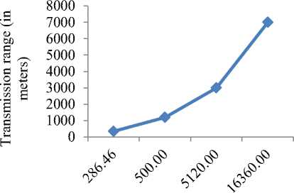
Transmission rate is directly proportional to bandwidth and bandwidth depends upon frequency. Thus, high frequency acoustic waves offer high transmission rates but at the same time they also suffer from attenuation and attenuation results in shorter transmission ranges. Low frequencies increase range but lead to limited bandwidth and low transmission rates. Fig. 1 clearly depicts that transmission rate decreases when transmission range increases. Further, note that transmission rate decreases drastically when range is above 1200 meters.
12000 ,й
Й ^8000
О 6
'Я R
8 6000
§ 5 4000
I 2000
Q
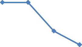
350 1200 4000 7000 Transmission range (in meters)
Fig. 1: Data transmission rate vs transmission range
In multi-hop communication, data is relayed using short range modem that provides high transmission rate over small range. In direct communication, nodes choose high range acoustic modem but it drastically slow down transmission rates so directly communication may work well when all nodes are located near to BS but cannot be used in large networks.
-
• Energy vs transmission range
Increase in transmission range increases results in high attenuation due to absorption and scattering. To receive an identifiable signal without errors, transmission energy of transmitted signal should be high. Figure 2 show overall energy consumption involved with a packet over different transmission ranges. It is clearly demonstrated in the fig. 2 that energy consumption increases dramatically when transmission range increases.
As we discussed earlier, energy is one of the major constraint in UWSN so to conserve energy short range transmissions are more favorable. It is pretty clear from the fig. 2 that when transmission range is above 1200 (as required in direct communication) energy consumption became unaffordable for acoustic modems, nodes will die quickly and this will reduce lifetime of network.
Energy consumed (in microJoules)
Fig. 2: Transmission range vs Energy consumed
-
• Packet transmission time vs transmission range
Packet transmission time increases with transmission range because increase in range results in decrease of transmission rate. It will ultimately leads to high packet transmission time especially for large distance. Moreover, signal propagation speed in acoustic is 1.5*103
meter/second which is five orders of magnitude lower than propagation speed of radio signals i.e. 3*108 meter/second. Fig. 3 shows packet transmission time w.r.t transmission range.
Packet transmission time (in milliseconds)
Fig. 3. Transmission range vs Packet transmission time
-
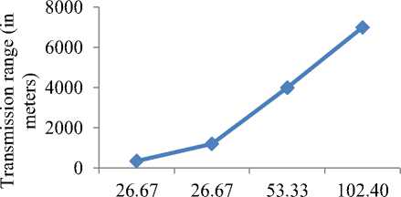
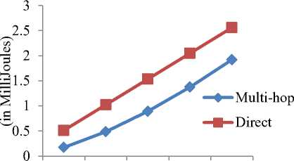
• Energy consumption vs network size
According to LEACH [15], each message in multi-hop communication traverses 0.6*sqrt(N) nodes to reach BS, where N is number of nodes in network. Nodes in multihop communication are deployed with UWM 1000 and nodes in direct communication are deployed in UWM 3000. Fig. 4 depicts energy consumption in transmission and reception of message when network size increases from 100 to 500. It is clear from the figure that direct communication consumes more energy than multi-hop, when number of nodes increases. If we increase monitored area then direct communication requires higher range acoustic modem than UWM3000 and this will further increase energy consumption.
100 200 300 400 500
Number of nodes
Fig. 4. Number of nodes vs Energy consumed
-
IV. Conclusion
In this paper, we have compared various communication methodologies (radio, optical and acoustic waves) to evaluate which one fits better in a watery environment. It is clear from the above discussion that acoustic works best in underwater environment. Further, we presented a new 3-dimensional dynamic communication architecture that uses acoustic links for communication. In this paper, UWSN is used as a special case for water quality surveillance application. We evaluated transmission rate, energy and transmission time to determine performance of multi-hop over direct communication. Simulation results depict that performance of multi-hop communication is much better than direct communication for UWSN in terms of transmission rate, transmission time and most importantly energy consumption because small amount of power is involved during transmission of signals over small distances. Also, loss in strength of signal due to absorption loss and scattering is very minute. It endorses proposed communication architecture that uses short range and multi-hop based acoustic communication.
References Communication Architecture for Underwater Wireless Sensor Network
- Akyildiz, I. F., Pompili, D., and Melodia, T.: 'Underwater Acoustic Sensor Networks: Research Challenges', Ad Hoc Networks, 2005, 3, (3), pp. 257-279.
- Cui, J. H., Kong, J., Gerla, M., and Zhou, S.: 'The Challenges of Building Scalable Mobile Underwater Wireless Sensor Networks for Aquatic Applications', IEEE Network, 2006, 20, (3), pp. 12-18, DOI: 10.1109/MNET.2006.1637927.
- Liu, L., Zhou, S., and Cui, J. H.: 'Prospects and problems of wireless communication for underwater sensor networks', Wireless Communications & Mobile Computing, 2008, 8, (8), pp. 977–994, doi>10.1002/wcm.v8:8.
- Preisig, J.: 'Acoustic Propagation Considerations for Underwater Acoustic Communications Network Development', ACM SIGMOBILE Mobile Computing and Communications, 2007, 11, (4), pp. 2-10, DOI: 10.1145/1347364.1347370.
- Yan, H., Shi, Z. J., and Cui, J. H.: 'DBR: Depth-Based Routing for Underwater Sensor Networks,' Proc. Int. Conf. AdHoc and sensor networks, wireless networks, next generation internet, Singapore, May 2008, pp. 72-86.
- Xie, P., Cui, J. H., and Lao, L.: 'VBF: Vector-Based Forwarding Protocol for Underwater Sensor Networks,' Proc. Int. Conf. IFIP Networking, Coimbra, Portugal, May 2006, pp. 1216-1221, DOI: 10.1007/11753810_111.
- Xie, P, Zhou, Z., Nicolaou, N., et al.: 'Efficient Vector-Based Forwarding for Underwater Sensor Networks,' EURASIP Journal on Wireless Communications and Networking, 2010, (4), pp. 1-13, doi:10.1155/2010/195910.
- Jornet, J. M.: 'Focused Beam Routing Protocol for Underwater Acoustic Networks', Proceedings of the third ACM international workshop on Underwater Networks, San Francisco, CA, USA, September 2008, pp. 75-82, DOI:10.1145/1410107.1410121.
- Uddin, Md. A., Rashid, M., Rahman, Md. M.: 'Priority Metric based Ad Hoc Routing for Underwater Sensor Network', I. J. Computer Network and Information Security, 2013, 12, pp. 1-11, DOI: DOI: 10.5815/ijcnis.2013.12.01.
- Sperling, M.: 'RF to DC Converter in SiGe Process,' Carnegie Mellon University, August 2003.
- Benelli, G., Pozzebon, A.: 'RFID Under Water: Technical Issues and Applications,' InTech: RFID Under Water: Technical Issues and Applications, June 2013, Chapter 18, pp.380-396, DOI: 10.5772/53934.
- http://mail.alquds.edu/~f2095/Communication%20I/PPT_ch1.pdf.
- Akyildiz, I.F., Pompili, D., Melodia, T.: 'Underwater acoustic sensor networks: research challenges,' Ad Hoc Networks, 3, (3), 2005, pp. 257–279.
- Lu, K., Liu, G., Mao, R., Feng, Y.: 'Relay node placement based on balancing power consumption in wireless sensor networks,' IET Wireless Sensor Systems, 1, (1), 2011, pp.1-6, DOI: 10.1049/iet-wss.2010.0004.
- Heinzelman, W. R., Chandrakasan, A., and Balakrishnan, H.: 'Energy-efficient communication protocol for wireless micro sensor networks'. Proc. Int. Conf. System Sciences, Wailea Maui, Hawaii, January 2000, pp. 3005-3014, DOI:10.1109/HICSS.2000.926982.
