Comparative account of robust h∞ techniques for missile autopilot design

Author: PSR Srinivasa Sastry, SK Ray, G. Mallikarjuna Rao, S. K. Biswas
Journal: International Journal of Image, Graphics and Signal Processing @ijigsp
Article in issue: 4 vol.11, 2019.
Free access
H∞ control techniques are prominently used as solutions for flight control problems. From the literature, a variety of techniques is reported in the last three decades with specific merits and demerits, which, when applied to multiple flight control scenarios, showing trade off in terms of performance and robustness. However, all these methods possess superior performance when compared with that of classical approaches. In this paper an attempt is made to provide an insight into the requirements and criticalities in the design of missile autopilot. This paper introduces some of the significant H∞ control techniques like H∞ mixed sensitivity, H∞ loop shaping and μ synthesis, with specific emphasis on analysis of autopilot design. A comparative account of modern control methods is presented on the basis of system performance and robustness, which will be helpful in the selection of the appropriate design method for specific application.
Robust control, autopilot, Missile control, Nonlinear control, Mixed Sensitivity, H∞ loop shaping, µ synthesis
Short address: https://sciup.org/15016045
IDR: 15016045 | DOI: 10.5815/ijigsp.2019.04.03
Text of the scientific article Comparative account of robust h∞ techniques for missile autopilot design
Published Online April 2019 in MECS DOI: 10.5815/ijigsp.2019.04.03
The major objective of a missile is to track the target and neutralise the threat scenario. In order to achieve this objective, the system must be designed for stability, robustness, fast response and accuracy. In addition, the cost effectiveness and minimum development time are also desirable. In general, a given missile system as shown in Fig. 1, can be divided mainly into four major groups, viz; (1) body or structural otherwise known as air-frame, (2) warhead, (3) propulsion and (4) Guidance Navigation and Control (GNC). Among these groups, GNC section is the most important part of missile systems due to the fact that GNC should guarantee and extract the highest quality performance of the missile system.
In the GNC group of missile systems, there are three distinct sub-groups, namely Guidance, Navigation, and
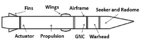
Fig.1. A General Homing Missile
Designing a flight control system (FCS) for any missile demands fulfillment of two top-level requirements over the entire flight envelope: first, exploring the full physical capabilities of the missile system and second, compensating the closed-loop transfer function taking care of unavoidable deviations from the assumed model[1].
Two types of steering logic are commonly employed for missile control namely, Skid-to-Turn (STT) and Bank-to-Turn (BTT). An STT missile is normally controlled by a set of four fins placed in a cruciform pattern around the tail of the missile. The name arises from the resulting motion when a turn is commanded. All the four fins are commanded in a mixed way to produce the desired turn of the velocity vector. At the beginning of a turn, the tail fins force the tail in the direction opposite to the desired direction of the nose of the missile which in turn causes the ’skidding’ motion where maneuvers are performed by commanding the changes in angle of attack and/or sideslip angle while maintaining zero roll rate. STT scheme is used when there is no preferred plane in which maximum lift can be generated. A BTT missile performs a maneuver by simultaneously rolling to the preferred plane of maximum lift and pitching with side slip regulated to zero such as in air-craft co-ordinated turns.
The important issues in the application of the control theory to the missile systems originate from the complexity of missile system itself. The missile system has to operate in a challenging environment due to (1) the speed of missile which is very high, (2) the system model is a six degree of freedom nonlinear equation with complex dynamic cross-couplings, (3) it operates in an extreme wide range of operational environment i.e., from humid tropical climate to the freezing North Pole region. These operating environments make missile control system design more challenging and complex in nature. Some of the important issues which complicate the missile autopilot design process are presented below.
-
· Nonlinear Parameter-dependent Dynamics: The complete rigid-body dynamics of the missile are highly nonlinear, with large coupling terms between the longitudinal and lateral dynamics. BTT Autopilot design gets more complicated than for an STT one, due to the dynamic coupling that occurs during roll maneuvers at high angle of attacks. Additionally, substantial variation occurs in the forces and moments generated by the missile body and control surfaces depending on the missile states.
-
• Nonlinear Parameter-dependent Dynamics: The complete rigid-body dynamics of the missile are highly nonlinear, with large coupling terms between the longitudinal and lateral dynamics. BTT Autopilot design gets more complicated than for an STT, due to the dynamic coupling that occurs during roll maneuvers at high angle of attacks. Additionally, substantial variation occurs in the forces and moments generated by the missile body and control surfaces depending on the missile states.
-
• Uncontrollable States: The key states that must be controlled to execute desired maneuvers depend on other states, such as missile speed, altitude, and pitch angle, which are not directly controlled. The controller must be robust enough to take care of the effects of variations in these states.
-
• Uncertain Aerodynamic Coefficients:
Aerodynamic coefficients are inherently uncertain with typical errors of up to 20%, with larger errors in cases of extreme flight conditions or where only sparse data is available.
-
• Measurement Noise: As in all control problems, the states cannot be measured perfectly. In this case executing maneuvers accentuates the effects of sensor noise on the system.
-
• Unmodelled dynamics: A tactical missile is long and slender resulting in significant flexural dynamics. Specifically body-bending mode dynamics due to structural flexibility is difficult to model completely. Although a missile air-frame is designed to keep the body-bending modes at as high a frequency as possible, the first few modes are usually low enough demanding special
attention to be paid. Accelerations due to bodybending dynamics are sensed by the inertial sensors as inertial accelerations, causing parasitic feedback effects that can destabilize the missile leading to so called control-structure interaction. Therefore, the rigid-body controller must have necessary attenuation at the frequencies of the bending modes to prevent excitation of the flexure dynamics.
-
• Actuator Saturation: Limited control authority will be available due to saturation of actuator deflection, deflection rate and deflection acceleration. Actuator saturation is a critical issue in a tactical missile autopilot design, since the guidance law will most likely command extremely large accelerations in the end-game of intercept mission. The controller has to be designed with the actuator limits in mind which otherwise would lead to actuator saturation related instability.
-
• Extreme Accelerations: The guidance law is likely to command maneuvers which exceed the capability of the airframe during the End-game. As there is no time to recover from any acceleration error at this stage, rapid and accurate tracking of commands approaching the limits achievable by the airframe is desired in this phase of missile flight.
Rest of the paper is divided into six sections. Section II provides brief historical background spanning from 1930 to 2010, Section III emphasizes on comparison between classical and modern approaches. Section IV discusses briefly various modern control methods that are in vogue. Section V provides description of important Robust H∞ Autopilot Design Techniques. Section VI lists the details of the recent trends from 2011 onwards while Section VII concludes the entire paper.
-
II. Historical Background
In the early classical control system design, the well-known systematic techniques like Nyquist, Nichols and Bode design procedures are developed during 1930s and 1940s respectively. These methods were primarily useful and provide lot of insight into time and frequency
behavior of single input single output systems. These techniques led to the creation of first generation of automatic feedback control system design. In the years 1960 and later, the limitations of classical control techniques have been addressed and solutions are identified with the theory of optimal control, which further led to the development of multivariable control design[2].
The H∞ techniques are proposed by Zames during the 1980’s [3] and these techniques took care of uncertainty in the models during design process. This can be equivalently represented in the form of either multiplicative or additive uncertainties suiting the specific problem at hand. The gain from the Small Gain theorem is that it minimizes the perturbed system’s H∞ norm and therefore, maximizes the unstructured uncertainty that the system can tolerate while guaranteeing the stability of the closed loop system. H∞ methods synthesize controllers that are inherently robust as they compensate for the worst case uncertainty while they are exposed to unnecessary conservatism most of the times.
The alternative development of solutions to the H∞ problem is proposed in 1990 by Green et al considering an approach based on J-spectral factorizations. In H∞ mixed sensitivity method, perturbation inputs, the inputs and the outputs to unstructured uncertainty models are shaped with the frequency dependent weights. The resulting mixed sensitivity H∞ problem minimizes the sensitivity functions while guaranteeing closed loop robust stability.
To attain the required robustness and performance, the weights will be adjusted during the design process in a repetitive manner. Chu et al[4] in the year 1986 worked on H∞ minimization problems by visualizing as general distance problem. Anderson and Moore[5] in the year 1989, explored Optimal control with Linear Quadratic Gaussian (LQG) techniques. Kasenally and Limebeer[6] in the year 1989, reported their work on problem of parametric mixed sensitivity which solves the optimal norm of H∞ problems by a non-iterative procedure. The magnitude of the co-prime factor perturbations was related to the gap metric by Georgiou and Smith in 1990 and demonstrated that the closed loop stability is a robust property of this method[2].
Yue[7] reported in the year 1990 by applying one degree-of-freedom of H∞ mixed sensitivity technique for applications like helicopter problems. Lundstrom[8] and Postlethwaite[9] et al in year 1993 and 1994 presented on two degree-of-freedom controllers of H∞ mixed sensitivity formulations.
During 1990s, H∞ mixed sensitivity loop shaping procedures are widely explored with one and two degree-of-freedom controllers. Harrier by Hyde[10] in 1995 applied one degree of freedom controller with loop shaping to Advanced Short Take Off and Vertical Landing (AVSTOL) by using longitudinal axis control. Hoyle[11] et al in the year 1991 and Limebeer[12] in the year 1993 proposed loop shaping using two degree of freedom controllers. Walker[13] in the year 1996 proposed formulation for loop shaping controller with the two degree of freedom.
Chen et. al in the year 2002 exploited the linear matrix inequality (LMI) technique to implement the H∞ guidance design considering control constraints[14]. Lim et.al in the year 2003 applied the gain scheduled autopilot for missile applications[15]. Spilios Theodoulis et. al in the year 2007 proposed a gain-scheduling controller for a missile autopilot[16]. S. N. Balakrishnan et.al in the year 2008 developed the Nonlinear H∞ Missile Longitudinal Autopilot design technique which provided an approximate solution to the Hamilton Jacobi-Bellman (HJB) equation[17].
Further research carried out in the field of Autopilot design after 2010 is presented in Section VI in tabulated form.
-
III. Classical versus Modern Approaches for Autopilot Design
Generally, given missile dynamics is highly coupled, unstable for high maneuvering capability, and sometimes non-minimum phase in case of tail control. The aerodynamic characteristics of the air-frame may not be accurately available which results in modelling of the system dynamics with lot of uncertainties. Autopilot design is a challenging task for this type of missile dynamics and has to ensure closed loop stability while being robust to parametric uncertainties and unmodeled dynamics.
Missile autopilot design is dominated by the usage of classical control techniques over the last few decades. Traditionally, the autopilot design approach involves the following procedural steps:
-
1) Select the operating points in the missile operating envelope and linearize the missile airframe dynamics around that point.
-
2) Decouple the control dynamics of roll, pitch and yaw of missile airframe by appropriate assumptions.
-
3) Choose a proper closed loop sensor-feedback configuration by using classical control theory for uncoupled roll, pitch and yaw dynamic channels.
-
4) Design the required compensators and compute the gains for the uncoupled roll, pitch and yaw channels to meet the desired Gain and Phase stability margins, and time response behavior like rise time, overshoot, settling time etc and attenuation of sensor noise, response to flexible modes etc.
-
5) Schedule the control gains between the operating points to take care of missile dynamics variation over the entire operating envelope.
The above approach proved to be effective in most of the cases. In[18] Arrow and Williams stated that constraints of unmodeled dynamics will be dealt better by using classical control theory techniques. However, this classical approach has some limitations due to decoupling aspects of the dynamics and cancellation of the cross coupling between channels leading to the design of separate autopilot each for roll, pitch and yaw control. Classical control design technique requires thorough knowledge to convert complex coupled system in to several Single Input Single Output (SISO) models with appropriate assumptions and simplifications to handle the multi input multi output (MIMO) nature of missile airframe dynamics. It needs a lot of earlier experience and exposure to effectively design the autopilot. Different designers come up with different designs for the same problem based on their experience.
Decoupling of missile airframe dynamics removes the opportunity to use the advantages of coupling paths which are beneficial in controlling the missile system. Generally in missile autopilot design with classical design technique, the designed compensators will be fixed in structure throughout operating points of the complete flight envelope and plant dynamics variation will be taken care by changing the control gains between operating points. Since the controller dynamics are fixed which compromises the autopilot’s achievable performance in terms of stability margins and time response. In addition, missile autopilot design using classical control methods needs an extensive prior design experience and is generally a time consuming process to freeze the final design.
Modern control techniques for missile autopilot design are expected to work directly with multi input multi output plant dynamics and provide a simple solution with the design process. This can be achieved in lesser design cycle time. The structure and dynamics of the controller can change between the linearized operating points of flight operating envelope. In[18], authors reported that modern control approaches can perform better when compared with classical approaches in designing a control law for a highly coupled system. Nesline and Zarchan[19] reported the advantages of modern control design techniques and analysis by using classical frequency response method. The idea is to identify disturbances which are unmodeled and could result in destabilization in the modern control design methodology.
-
IV. Autopilot Design Methodology – Various Modern Techniques
Future missile autopilot systems design will possess the requirement of more and more agility over the complete flight envelope. The key issues in the design of next generation missile autopilot includes (a) quick response to attitude or acceleration commands, (b) assured robustness under high manoeuvrability conditions with wide range of mission operating profiles, (c) guaranteed robustness and performance against aerodynamic parameter uncertainties, thrust profile uncertainty, control surfaces effectiveness uncertainty along with missile mass and moment of inertia variation, (d) the attenuation of highly coupled and non-linear missile dynamics under high angle of attack scenario.
The development of Eigen structure assignment, Linear Quadratic Regulator (LQR) control, non-linear control, robust control, adaptive control and intelligent control methods influenced revolutionary changes in missile autopilot design. They provided the powerful control design tools to cater to the key issues mentioned above. A brief discussion is provided below.
Eigen Structure-Assignment Design Technique:
This method is the multivariable expansion of a root locus technique. The multi input multi output behaviour is characterized by Eigen-vectors and Eigen-values. The stability is determined by eigen-values, furthermore the eigen-vectors characterize the shape of the response and coupling of different modes. It is mostly concerned with eigen-values and their related eigenvectors placement by feedback, to get desired system performance like closed loop damping, settling time, rise time and system decoupling parameter specifications.
LQR Design Technique:
The LQR control method is a well-developed control design technique. The gains of the LQR control problem are computed simultaneously by minimizing an appropriate performance index (PI), generally a quadratic cost function integral. The design synthesis will be carried out in the time domain. In[20], the missile flight control system design using LQR design techniques, describing various LQR formulations for the design of lateral acceleration autopilot in single plane is reported.
Robust Control Design Technique:
Robust control design techniques address various methods for multivariable autopilot design which satisfy the system performance specifications along with guaranteed stability under perturbed flight conditions or when missile is subjected to external disturbances. Several Robust control design techniques are developed and applied for missile autopilot. Research work is carried out with different ways of robustness assessment of missile autopilot design using Quantitative Feedback Theory (QFT), H∞ control, 1^ synthesis, Linear Matrix Inequality (LMI) control, Normalised Co-prime Factor loop shaping H∞ control and etc. Some of these methods are briefly explained in Section V.
Adaptive Control Design Technique:
Adaptive control design technique will adjust the controller gains on-line to take care of unknown parameters, changes in system dynamics along with unknown external disturbances. Adaptive control laws can be divided into two general classes namely direct and indirect. A simple example of indirect adaptive control design technique is that the autopilot design using prestored gain schedule with respect to some of flight parameters, where the gains are calculated off-line with different flight operating points to meet the autopilot specifications. Direct adaptive control design technique will update the gains of the autopilot on- the-fly directly with the help of system inputs history and tracking errors.
Intelligent control Design Technique:
Missile autopilot design needs to tune the control parameters to get required performance. With the help of artificial neural network theory in the process of tuning, the process of control parameter adjustment can be standardized. To achieve this, we need to build the performance model with the required flying qualities. The structure of the autopilot is prefixed with the undetermined parameters. By comparing the performance of actual system with the required flying qualities, the artificial neural network is trained using training algorithms to learn the tuning rules. Hence, the parameters of the autopilot can be updated to obtain required performance.
-
V. Robust H∞ Autopilot Design Techniques
Modern robust controllers can be classified as linear and nonlinear depending on the systems for which the controllers are designed. They can also be classified into Structured and Unstructured depending on the type of uncertainty they are expected to handle. If the uncertainty is traced to the parameters of the system and hence to the coefficients of the Transfer Function of the Plant, then a diagonal uncertainty block is pulled out of the plant to represent Structured Uncertainty. The variation in the frequency response can be obtained by experimentation or by other means and can be represented as a percentage change over a nominal model. Then, it can be expressed as additive or multiplicative uncertainty which is represented as an Unstructured Uncertainty.
The singular values σ i , represent the gains that the given system applies in a given direction of multivariable input signals. The maximum or supremum singular value , is the maximum gain in all the input directions that occur in a given plant and is given by the H∞ norm of the system. The smaller it is the better in terms of robustness of the plant. H∞ controller minimises the maximum singular value taken over all frequencies in order to provide stability in the presence of maximum variations in the plant response due to uncertainties and this is called Robust Stability. By utilising the structure in the uncertainty, Structured Singular Value (SSV) , is obtained for a given uncertainty structure which is smaller than or equal to H∞ norm and hence the synthesized controllers provide better robust stability and this method is called µ-synthesis. The following description briefly explains some of the commonly used important H∞ based Robust Control methods which would help the reader to understand in a better way.
-
1) H∞ Design
The objective here is to find an H∞ Optimal, output controller for the interconnection shown in Fig. 2, which depicts the generalized plant P and the controller K. The exogenous outputs are z and w are the exogenous inputs. The Sensor measurement outputs are y and u are the control inputs to the Actuators. The w inputs comprise of reference signals, disturbances, noise or outputs of uncertainty models as perturbations. The z outputs maybe the inputs to uncertainty models, errors or cost functions which are to be minimized to meet certain performance requirements.
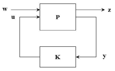
Fig.2. Standard H∞ problem
Then, the open loop system P of Figure 2 is
z
y
P 11 P 12
P 21 P 22
w „ w
u u
The Transfer Function from w to z can be written as
T zw = P i + P i2 K ( I - P 22 K ) - 1 P 21 (2)
It is also called the Lower Linear Fractional Transformation (LLFT). It is written as F l (P, K). The standard H∞ optimization problem is to obtain a proper and stabilising controller K that minimizes the supremum singular value of T zw over all frequencies. The minimum closed loop norm of T zw of all stabilising controllers K is denoted by ɣ opt ,
Y opt
min stab . K
II T zw\ L
Where
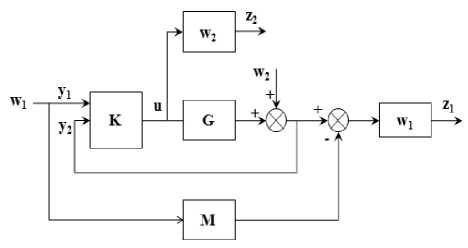
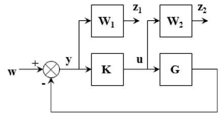
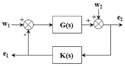
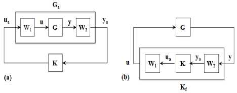
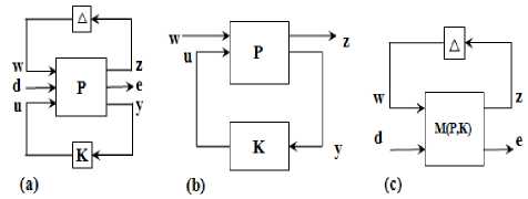
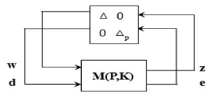
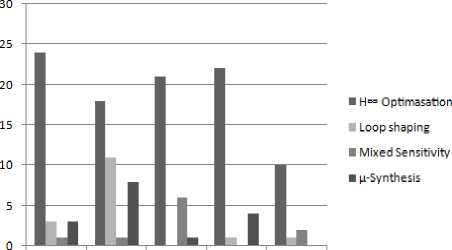
HTZW!^" 0 A stabilising controller achieving ɣopt is said to be Optimal Controller. A Sub Optimal stabilising Controller achieves ɣ greater than ɣopt. 2) H∞ Mixed Sensitivity Design A. One Degree of freedom Controller Fig. 3 shows a closed loop feedback system with reference signal w, error y, control signal u, output disturbance d and output z with the Plant G. It can be shown that y = (1 + GK )-1( w - d) z = (1 + GK )-1( d + GKw) (5) Output sensitivity S0, is defined as 5о = (1 + GK )-1 (6) Fig.3. One degree of freedom Controller B. Two Degree of Freedom Controller Fig.5. Two degree of freedom Controller Smaller singular values of S0 (larger singular values of K) result in smaller tracking errors and provide good disturbance rejection. This will be required up to the bandwidth frequency. Fig. 5 shows the closed loop diagram of two degree of freedom controller, where the Controller K is divided in to two parts, K1and K2acting on reference inputs W1which is equal to y1and feed-back signals y2respectively and independently. The control input u is a combination of K1 and K2 as K= [K1 K2] given below. U = K (I + GK )-1= KS0 = (I + KG)-1K = Sk (7) u = (K 1 K 2)( y-) y2 5 = (1 + KG )-1 (8) Where, Si is defined as input sensitivity. To be robust and to limit the control effort u, KS0 should have smaller singular values at high frequencies where the model uncertainties and sensor noise are high. To meet both low and high frequency requirements on K, the design can incorporate frequency dependent weights as given in the Figure 4. Fig.4. Controller with Frequency dependent weights W1 and W2 K1 and K2 can be understood to be pre-filter and feedback controller respectively. M is the reference model whose output should be followed by the Plant. The Deviation from the desired output from M and the output of the actual Plant is weighted by W1 to form the exogenous output Z1, which will be minimised by the design procedure as in the earlier schemes. In a two-step design, K2 can be first synthesized first to meet the robust stability against the disturbances and uncertainties and K1 later to meet the performance requirements. K1 and K2 can be synthesised in one step resulting in a low order controller while two step method provides a better flexibility in design. It can be shown that the closed loop transfer function is T TZW W1( S о GK1 - M) W1 S о W2SiK1 W2K2S0 The H∞ Mixed Sensitivity Optimal control problem is to obtain a stabilizing K such that Where input and output sensitivities are So = (1 + GK)-1 and Si = (1 + KG)-1 . The weighted functions to be minimised are the Deviation of the actual output from the desired output, Output Sensitivity and Control effort to Reference signals and Outputs. II Tzw\ L W1S0 W2S0 < Y 3) H∞ Loop-shaping Design This design methodology was proposed by McFarlane and Glover. The Transfer function of the closed loop system shown in Fig. 6 is Where, W1 and W2 normally will determine the performance and robustness properties respectively. W1 and W2 possess low pass and high pass filter characteristics respectively to meet the design goals. к e 2 J e1 ( KSG KS ) w1 кSG S v к w2 J Fig.6. H∞ problem with two inputs and two outputs In order to perform tuning, loop shaping is carried out prior to solving for the above. For this, G is replaced by Ga =W2GW1 as shown in Fig. 7a. W1 and W2 are pre and post compensators designed as per the known procedures in classical control. Integral action and high frequency roll-off can be introduced with these compensators. Now the controller K is obtained for the compensated plant i.e., Ga by solving the H∞ problem as given below. Where, sensitivity S(5) = (1 + G(5)K(5)) 1. For a given ɣ > 0, the problem is to find a stabilizing controller K such that, KSG KS SG S № KSaGa KS < y The minimum value of ɣ, ɣmin can be a priori computed as SaGa Sa Fig.7. a) Compensated Plant b) Final Controller y > y „„ = (1+supA (YX A (14) i Where Where X and Y are solutions of two Ricatti Equations obtained from a given G = [A, B, C] as ATX + XA - XBBT X + CTC = 0X > C (15) AY + YAT - YCTCY + -BBT= 0Y > 0 Such a controller K can be obtained as K(5) = -y2BTX(sI - A + BBTX - y2ZYCTC)-1ZYCT Where Z = (1 - y2) In + YX )-1 (17) ~~ Let G(S) = M (S)-1N(S) be the normalized coprime ~~ factored representation whereM(S), N(S) are proper and stable transfer functions. Let P be a family of perturbed plants such that Д Д MNю ~~ P =ш +Д ~)-1( N +Д ~) with MN Stabilization problem is to find largest £, i.e., ^ , such that all plants in P can be stabilized by the same controller K. It is established that £ is the inverse of max γmin. This is the trade-off relation between performance and robustness. Sa (s) = (1 + Ga (s) K (s ))-1 (19) Once K is obtained, the final controller Kf to be implemented will absorb W1 andW2, i.e., Kf =W1GW2, as shown in Figure 7b. 4) μ-Synthesis design : It is a multivariable robust design technique combining H∞ control and structured singular value (SSV) or μ analysis. The μ-Synthesis design takes care of the measurement noise, disturbances and model uncertainties into account. The uncertainties are pulled out and arranged in a feedback loop form as shown in Figure 8a. The design goal is to find a stabilising controller K that minimizes the H∞ norm from d to e, robustly stabilizes the plant and keeps e within limits specified i.e., the performance against all perturbations given by . The procedure starts by recasting the problem in to standard H∞ problem by clubbing w, d and z, e together into w and z respectively and ignoring for the time being, as given in Figure 1 which is reproduced in Fig. 8b. Fig.8. a) General Robust control problem b) Synthesis Framework c) Analysis Framework Once the Controller K is synthesized, the closed loop system is represented in an (M, ) structure as shown in Fig. 8c, with M partitioned as M = M11 M21 M12 M22 The transfer function from d to e can be expressed as the Upper Linear Fractional Transformation (ULFT), Fu (M; ∆). e = F (M, A) d (21) Where Fu = M 22 + M 21A( I — MnA)—1M 12 (22) With no uncertainties (∆=0), the Nominal Stability (NS) can be checked using the poles of the closed loop system M. When d and e are normalised to unity in the plant P, the Nominal Performance (NP), i.e., with ∆ = 0, is satisfied if and only if the following is true. sup — M22 L = ^(M22(jW))< 1 (23) w Robust Stability (RS) is satisfied if the closed loop remains stable for all uncertainties in the perturbation set ∆. When the uncertainties have no structure but bounded i.e. 1, the Robust Stability Unstructured (RSU) is satisfied if and only if the following is satisfied. sup - - IIM11 L= J^( M „( jw)) < 1 , o-(A) < 1 (24) When the uncertainties exhibit some structure, the above Robust stability estimate is conservative and the Structured Singular Value μ reduces this conservatism. The structure in the uncertainty can be represented by the set A , comprising of block diagonal complex valued perturbation as given below. A = diag[5Im, 5, A3]: 55 e C and A3e Cnim (25) BA is bounded subset of A such that BA = A e A : <r(A) < 1 Then the Structured Singular Value p of M (jw) with respect to the block structure A is defined as given below. д(M(jm)) = 1 :det( I + M(/m)\ 0 min A :det( I + M (jm) # 0 I n Here μ is the inverse of smallest perturbation of ∆ that destabilizes M and hence, μ is a measure of robustness of the closed loop system against the structured perturbations. The supremum of μ over the frequency indicates the amount of uncertainty the system can tolerate before becoming unstable. The μ cannot be computed easily with the above equation as it is not globally convex. However, useful limits on p can be found for a given A , as shown below. P(M (jm))< Д(M (jm)< ^(M (jm)) (27) Where p(M (jm)) is the Spectral radius of M(jm) . The bounds above are not tight and hence not useful. To produce tighter bounds, two transformation matrices U and D for a given A , are defined belonging to the sets U and D respectively and have the same structure as A . U is unitary (U*U = I) and D is invertible. Then the following is true. ^(AU) = ^(UA), AeA DAD-1 =A, D e D(29) Then the tighter bounds on can be inf — sup P(M(jm)) < Д(M(jm)) < л _ n CT(DM(jm))D—1 UeU The upper bound is of interest and can be found as the optimisation problem is convex and hence upper bound close to μ can be obtained in most cases, and will be used in determining the stability. Fig.9. Robust Performance Evaluation using Robust Stability Test for Structured Perturbations The Robust Stability for Structured perturbations (RSS) is then stated as F (M,∆) stable for all : ∆ ∈ B∆ If sup inf D∈Dσ(D(ω))M11(jω)D(ω)-1≤1 Robust Performance for the structured perturbations (RPS) is the capability of the closed loop system to meet the performance requirements against all ∆ in set the ∆ . RPS can be evaluated using RSS conditions by augmenting the ∆ block with ∆ as shown in the Fig. 9. ~ The augmented ∆, ∆ = diag [∆, ∆ ], which is used for testing RPS and then RPS is stated as F (M,∆) stable and F (M,∆) ≤1,∀∆∈B∆~ If sup ω inf - σ(D(ω))M (jω)D(ω)-1≤1 Ultimately any controller design should satisfy Robust Performance requirements and hence the condition for RPS should be the checked against all controllers K and choose the one that minimizes μ. The M(P,K) used above is the LLFT i.e., Fl(P;K). Hence, the μ - synthesis is an optimization problem in two variables K and D that solves the following iteratively. KDII DF(P, K)D-1 II∞ This is carried out until the following condition is achieved. IIDF(P, K)D-1II ≤1 (36) For a given D, the H∞ control problem gives a controller K as a solution. For a fixed controller K, an optimal D-Scale can be computed and the above condition is checked. If it is not met, K is found for the new D-Scale and this process can be iterated until the H∞ norm above is close to its μ value. This is known as DK Iteration procedure. The optimization problem is convex when one variable is fixed. However, this process does not guarantee convergence to the global optimal values of K and D. If the above condition is not met at all, then some specifications on either performance or on stability should be relaxed as they are unrealizable or too tight. The Fig. 10 and 11 given below show the Scopus analysis of the number of papers published using both H∞ techniques in general and H∞ techniques for Autopilot design for missiles respectively. As seen in the figures, the Growth in the research work using H∞ techniques for general applications as well as for missile applications is almost exponential. Fig. 12 gives the number of papers published using different techniques against the period as shown. The H∞ Optimization method seems to be the most popular method and is applied for a large number of problems for all periods of time. The other methods have been applied in varying proportion in different time periods. The Table given in the next section shows the important research work carried out in this field, the results presented by the authors of the research work along with the comments from the authors of this paper. Fig.10. H∞ techniques applied for different applications Fig.11. H∞ techniques applied for missile autopilot design The following Table 1 provides the latest research in the area of Autopilot design for missile applications using different modern H∞ Robust Control methods. Along with the methods used, Results reported by the authors followed by remarks are included in the Table 1. 1990-97 1998-02 2003-07 2008-12 2013-17 Fig.12. Trend of the No. of papers published using different Techniques Table 1. Recent methods used for the autopilot design Sl No Title of Article Method used Result reported by the authors Remarks by the author of this paper 1 On decoupled or coupled control of bank-toturn missiles In[21], this work, LQR and a better H∞ controller method is used From the observed simulation results, authors showed that the decoupled controller is having less performance than the tracking effect of a coupled controller. Authors observed that with the use of some special parameters for the decoupled controller, the performance improved. 2 Fault-Tolerant Sampled- Data Mixed H∞ and Passivity Control of Stochastic Systems and It Application[22] In this work, mixed H∞ and passivity conditions are used. It is observed that systems accompanied with actuator failures are stabilized by designing the reliable sampled data controllers. Sufficient LMI conditions ensuring stability are derived. Method to adapt control gain matrix is provided when actuator fails to achieve fault tolerance 3 Robust H∞ Autopilot Design for Agile Missile with TimeVarying Parameters[23] H∞ loop shaping method is used. It is observed that by applying the satisfactory tracking, autopilots have shown robustness on different parameter variations. The nonlinear autopilot controller based on back stepping shown less performance than the proposed pitch based autopilot controller design. Satisfactory tracking performance as well as robustness over complete flight envelope is observed and the proposed work on autopilot has a very simple structure, it does not take much time for gain scheduling activity. 4 Pitch / Yaw Channels Control Design for a 155mm Projectile with Rotating Canards, using a H∞ Loop-Shaping Design Procedure[24] In this work, authors have used the loop shaping based H∞ controller design method. The designed controller offered excellent reference tracking performance even though it is very of low complexity in the structure with decoupled dynamics. It is observed that stability of the closed loop system is ensured, performance achieved is satisfactory in spite of good amount of uncertainty on the parameters used. 5 Nonlinear H∞ Guidance Law Design for Near Space Interceptor based on Galerkin Simultaneous Policy Update Algorithm(GSPUA)[25] Nonlinear H∞ control approach is used. The interception time as well as Miss distance of the proposed method has shown better results than the traditional method. The proposed work can stabilize the guidance system and can meet the required disturbance constraints based on the proposed GSPUA technique by using the nonlinear H∞ controller design. 6 Fixed Structure H∞ Control for a Canard-Guided Projectile Pitch/Yaw Dynamics Autopilot Design[26] In this work, authors have used the one degree of freedom based H∞ controller design with fixed structure as well as fixed order. The proposed design considers the sensor position in the design procedure. It is observed that with the use of μ - analysis and Monte Carlo techniques, robust stability has been shown. Authors observed that with the use of weighting filters, target model parameters and controller structure, the proposed solution has given the autopilot design very good robustness against the uncertainty and modelling errors and also the proposed work optimizes the performance matching to specifications which are given as function of operating conditions. It is found that the same satisfactory results are obtained with the full order controller. 7 Robustness Analysis of Feedback Linearization with Robust State Estimation for a Nonlinear Missile Model[27] A robust H∞ filter is used. It is observed that the proposed filter performed well in all simulations, even with the presence of time varying uncertainty. The proposed H∞ filter controller design methods can be applied successfully to a nonlinear, uncertain system with a simple feedback linearization controller. 8 Robust H∞ Decentralized Fuzzy Tracking Control for Bank-to-Turn Missiles[28] Authors have proposed a robust H∞ based decentralized fuzzy model which is a reference tracking control design with uncertain parameters and external disturbances. It is found that the simulation results shown effectiveness in the presence of external disturbances. The outcome of the existence of the robust H1 controller design based on the decentralized fuzzy tracking controller is presented in terms of a set of LMIs, (Linear Matrix Inequalities) which solved the problem very efficiently with the usage of the convex optimization techniques. 9 The autopilot design of bank-to-turn missile using mixed sensitivity H∞ optimization[29] LQR control approach and mixed sensitivity H∞ optimization is used. It is observed that the proposed autopilot for BTT is very much effective with the use of six degree of freedom for the controller design and also for the target interception. The inner-loop controller design based on the LQR method aimed at containing the system within certain limits to get the satisfactory performance. To deal with model uncertainty and disturbances, the outer loop technique used mixed sensitivity H∞ optimization approach. 10 Tracking performance analysis of flight control system based on H∞ theory[30] H∞ control method is used. Robust Tracking Performance Criterion is defined. A procedure to evaluate this over the entire parameter space using linear models. A procedure for Flight Control Law Clearance is proposed for a given uncertain parameter space. A method is provided to identify flyable region in this space for guaranteed robust performance. 11 H∞ Robust Gain- Scheduled Autopilot Design for Portable Missile[31] In this work, a robust gain schedule based H ∞ technique has been proposed. From the experimental results, it is observed that very good tracking performance results are found with the usage of gain scheduled based H∞ controller design. In this work, authors have proposed a new robust gain-scheduled control structure. 12 Longitudinal Autopilot Design for Agile Turn Using Mixed H2 / H∞ Control[32] Mixed H2 / H ∞ based control design method is used for the autopilot design. The validation of the controller proposed has shown very good results based on numerical simulations. The proposed autopilot satisfied the mixed H2/ ∞ controller design. Performance conditions based on different multi-models which have been derived by using the local linearization for different operating angle of attack points along with usage of Mach number. 13 Network-Based H∞ Output Tracking Control for Systems with Time-Varying Bounded Delay[33] In this work, authors have used a controller design based on decentralized H ∞ technique. It is observed that output of the plant can track with high precision output of the reference model by using network based on H1 output tracking based control. It is also found that within a very short time the angle of attack is established with very small associated pitch rate. In this work, authors have proposed LMI (I) based procedure which has been adopted for designing a state feedback decentralized controller. It has guaranteed that the closed loop system tracking performance with a reference of an output of existing reference model well in H ∞ sense. 14 Study on Autopilot Dynamics with Robust Guidance Law and Terminal Constraint in Mechanical Engineering[34] H ∞ control method is used. When the case is with little target information, the proposed guidance law has shown more robustness in meeting the guidance precision and impact angle. The proposed method can be applied in the cases with high-order autopilot dynamics. 15 Self scheduled H ∞ Loop Shaping control of a Missile[35] The controller is designed by LPV (Linear Parametrically Varying) Synthesis which is applied to loop shaping criteria based on the H ∞ technique. The performance analysis as well as robust stability can be first verified by using the linear analysis techniques, again second time checking by using the nonlinear simulation by taking all the possible scheduled parameter variations and aerodynamic conditions. The proposed controller design has a dependence on the parameters like Mach Number, altitude and angle of attack. It meets the given specifications on a wide range of flight operating envelope. 16 Two-Degree Controller Design for Flexible Missile Based on H-inf Interference Suppression[36] State space model of rigid body with flexible missile model in the pitch channel is given. It is found that the problem of standard H ∞ control is being regarded as a problem of interference suppression. It is observed that with the application of LMI theory, authors have designed a 2- degree of freedom H∞ controller. From the system simulations results, it is found that the 2 degree H ∞ controller has the capability of restraining the interference signals. In this work, authors have considered the vibration and noise inputs as interference signals. The pitch rate, pitch angle, trajectory obliquity are considered as state variables. The output measurement parameters are pitch rate and pitch angle. 17 2 DOF H- Infinity Loop Shaping Robust Control for Rocket Attitude Stabilization[37] In this work, the authors have developed a model in such a way that the pitch rate control is analysed which is in turn related to the rocket’s longitudinal stability. It is observed from the simulation results that with the use of 2 degree of freedom based loop shaping controller, the longitudinal stability has been improved. The authors found that with the use of 2 degree of freedom based H ∞ loop shaping controller has shown better results in terms of robustness, it also reduced the control effort by not degrading the overall performance. 18 A Robust and Self- Scheduled Longitudinal Flight Control System: a Multi-Model and Structured H∞ Approach[38] The authors have shown a robust control system design for a longitudinal FCS (Flight Control System).With the use of an priori fixed control based structure, the H∞ control design framework is thoroughly explored From the experimental results, it is observed that the gain scheduling controller has shown robust performance results. It is also aligned to the standard H∞ design approach. The proposed approach is a good fit and very much promising for industrial related applications. 19 Application of H ∞ and μ -synthesis Techniques for Reusable Launch Vehicle Control[39] In this work, lateral and longitudinal autopilot design for the launch vehicles by using the H∞ and μ –synthesis controller design techniques have been thoroughly explained. From most of the applications, H ∞ controller alone is sufficient which resulted in lower order controller. It is shown that the μ -synthesis controller has an advantage of taking care of complex uncertainties in design stage itself. 20 Clearance of Flight Control Law Based on H∞ Theory[40] The proposed H ∞ approach is developed from general H ∞ theory and is applied to the clearance of a flight control law for a missile. A BTT missile is chosen as an example to test the proposed method. The simulation result shows that the proposed method is convenient and efficient. Based on bounded real lemma, two theorems about clearance are deduced, and the clearance problem is transformed to a general linear matrix inequality problem. 21 Design and application of gain-scheduling control for a Hover: parametric H ∞ loop shaping approach[41] In this work, authors have proposed loop shaping based gain scheduled H∞ controller. The proposed approach addressed the LMI framework based on parametric H ∞ loop shaping method. The authors have applied the proposed controller design successfully to a 3 degree of freedom based on Hover Didactic Plant (HDP) design. It is also observed from the experimental results and robust analysis that the controller design has an advantage for this type of design applications. By using the free parameter methods, design freedom can be added easily by scaling the design problem which is an advantage of the proposed method. 22 Fixed Structure H ∞ Control for a Canard- Guided Projectile Pitch/Yaw Dynamics Autopilot Design[26] In this work, authors have proposed a signal based H1 control with a single operating point. The design is for pitch/yaw autopilot for a 155mm guided projectile with dual spin canard guidance With the given uncertainty levels for the parameters, robust stability has been proved with the use of μ -analysis and Monte Carlo technique’s. Experimental results show that if the weighting filters, target model, parameters and controller structure are chosen judiciously, the solution can give a robust autopilot with uncertainty modelling. From the design, it is observed that the proposed method can be further extended over the complete flight envelop to obtain the gain scheduling control scheme. 23 H2 analytical decoupling design for a High-Angleof-Attack missile[42] Instead of considering the model disturbance in the design of controller theoretically such as in u-synthesis and H ∞ control methods, the H2 analytical decoupling method is considered for designing the decoupling controller for the high angle of attack control of missile. Simulations illustrate that the designed controller has good setpoint tracking and disturbance rejection ability while maintaining strong decoupling capability. The designed controller can be adjusted by the parameters in the controller. 24 The H ∞ Controller Design Including Control Allocation for Marine Vessel[43] In this work, authors have proposed novel concept of using actuators for the mooring control problem which is used in marine vessels. Authors have found that the control performance, system stability and allocation problem can be merged with the use of linear matrix inequality (LMI) techniques based on H∞ control concepts. It is also found that the proposed technique has given the assurance on the stability of complete control system. Dimension problems between inputs and outputs can be solved by proposed method. 25 Nonlinear H2 Lateral Control Design of Missiles[44] In this work, authors have developed a nonlinear H2 lateral control law which has successfully helped in increasing the manoeuvrability for the later control of nonlinear missile systems. There are some important advantages found for the proposed H2 design algorithm for attitude tracking missile applications when there is a necessity of lateral control conditions to be applied. When there is a need for effectiveness of regular aerodynamic surface is to be reduced, the proposed work is suitable for the missile development with the high performance manoeuvrability. 26 Robust Autopilot For A Flexible Missile: Loop Shaping H∞Design And Real V-Analysis[45] In this work, authors have developed a Loop shaping based H1 controller technique for autopilot design. Robustness is estimated by using v-analysis tools instead of μ -tools. From the experimental results, it is observed that the proposed method has shown robustness and good performance with nonlinear models and uncertainties, also the validation is done with a 6 degree of freedom simulations for missile motions. Authors have preserved the solid physical sense by designing the robust controller design using H1 loop shaping method. The Robustness is estimated via v-tools eliminating dense frequency gridding required for μ estimate. 27 Tracking performance analysis of flight control system based on H∞ theory[30] Authors have attained a robust tracking performance by usage of H ∞ design for the flight control system clearance application From the experimental results, it is observed that the clearance result and process is validated for the BTT (Bank To Turn) missile. It is found that when the Flight Control System (FCS) is suffering from uncertain parameters, then the proposed design guarantees accurate and fast tracking of specific target trajectory. The constituent systems and subsystems of a typical missile showing the place, role and importance of an autopilot are introduced. Turning manoeuvres are generally controlled by Skid to Turn or Bank to Turn approaches. STT scheme is widely used when there is no preferred plane of maximum lift. The critical issues involved in the design of an autopilot are listed out. Evolution of autopilot design from classical to modern techniques over the period of time is presented. The classical methods visualise the system in the form of linearised expressions of SISO models for tractability. Decoupling of Pitch, Yaw and Roll channels become necessary requirement. Decoupling of missile airframe dynamics removes the opportunity of utilising the advantages of coupling paths which are beneficial for controlling the missile system, leading to modern methods. Modern control techniques for missile autopilot design are expected to work directly with multi input multi output plant dynamics and provide appropriate solution with defined design process. This should be achieved in lesser design cycle time. Consequently Eigen structure assignment, Linear Quadratic Regulator (LQR) control, non-linear control, robust control, adaptive control and intelligent control methods influenced the design of missile autopilot. The main objective of H∞ Optimal design is to find stabilising controller for the interconnection with an understanding of maximal robustness or maximal performance as a base criterion, leading to guaranteed fulfillment of one against other. By utilising the structure in the uncertainty, Structured Singular Value (SSV) μ, is obtained for a given uncertainty structure which is smaller than or equal to H∞ norm and hence the synthesized controllers provide better robust stability in μ-synthesis design. Mixed sensitivity single degree freedom model provides the tradeoff between stability and control errors. Mixed sensitivity two degree freedom model exploit independent tuning process for performance and stability, exploring the combinations of robustness and performance trade off from the entire system point of view. The synthesis and analytical framework of these models are presented in the section robust autopilot design techniques. As depicted, the research work carried out using Modern H∞ techniques is growing almost exponentially both in general applications as well as for the missile autopilot design. H∞ Optimization method is applied in the missile autopilot design more than any other robust control method over all the periods of time and is likely to remain so in the future also.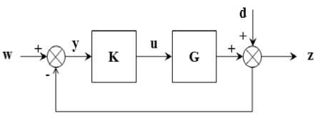


VI. Analysis of Latest Research on Controller Design
VII. Conclusions and Future Scope
References Comparative account of robust h∞ techniques for missile autopilot design
- F. Peter, F. Hellmundt, F. Holzapfel, and F. Chew, “Anti-Windup Command Filtered Adaptive Backstepping Autopilot Design for a Tail-Controlled Air-Defense Missile,” pp. 1–19, 2013.
- M. R. Tucker, “Continuous H_INFTY and Discrete Time-Varying Finite Horizon Robust Control with Industrial Applications,” 1998.
- G. Zames, “Feedback and Optimal Sensitivity: Model Reference Transformations, Multiplicative Seminorms and Approximate Inverses,” IEEE Trans. Automat. Contr., vol. 26, no. 2, pp. 301–320, 1981.
- J. C. D. and E. B. L. C.C. Chu, “The General Distance Problem in Koo Optimal Control Theory,” Int. J. Control, vol. 44, pp. 565–596, 1986.
- B. D. O. A. and J. B. Moore, Optimal Control: Linear Quadratic Methods. 1989.
- E. M. K. and D. J. N. Limebeer, “Closed Formulae for a Parametric Mixed Sensitivity Problem,” Syst. Control Lett., vol. 12, pp. 1–7, 1989.
- A. Y. and I. Postlethwaite, “Improvement of Helicopter Handling Qualities Using -Optimisation,” in IEE Proceedings, Part D: Control Theory and Applications, 1990, pp. 115–129.
- S. S. and J. C. D. P. Lundstrom, “Two Degree of Freedom Controller Design for an Ill-Conditioned Plant Using u-Synthesis,” in Proceedings of the European Control Conference, 1993, pp. 969–974.
- N. P. F. and D. J. W. I. Postlethwaite, “Walker. Rotorcraft Control Law Design for Rejection of Atmospheric Turbulence,” in Proceedings of IEE Conference Control94, 1994, pp. 1284–1289.
- R. A. Hyde, H_INFTY Aerospace Control Design. A VSTOL Flight Application,” Adv. Ind. Control Ser., 1995.
- R. H. and D. J. N. L. D. Hoyle, “An H_INFINITY Approach to Two Degree-Of-Freedom Design,” in Proceedings of the IEEE CDC, 1991, pp. 1581–1585.
- E. M. K. and J. D. P. D.J.N. Limebeer, “On the Design of Robust Two Degree of Freedom Controllers,” Automatica, vol. 29, no. 1, pp. 157–168, 1993.
- D. J. Walker, “On the Structure of a Two Degree-of-Freedom H_INFTY Loop Shaping Controller,” Int. J. Control, vol. 63, no. 6, pp. 1105–1127, 1996.
- Bor-Sen Chen, Yung-Yue Chen, and Chun-Liang Lin, “Nonlinear fuzzy H/sub ∞/ guidance law with saturation of actuators against maneuvering targets,” IEEE Trans. Control Syst. Technol., vol. 10, no. 6, pp. 769–779, Nov. 2002.
- Sungyung Lim and J. P. How, “Modeling and H/sub∞/ control for switched linear parameter-varying missile autopilot,” IEEE Trans. Control Syst. Technol., vol. 11, no. 6, pp. 830–838, Nov. 2003.
- S. Theodoulis and G. Duc, “Static interpolated ℋ∞ loop-shaping controllers for missile autopilot synthesis,” in 2007 46th IEEE Conference on Decision and Control, 2007, pp. 2385–2392.
- M. Xin and S. N. Balakrishnan, “Nonlinear H ∞ missile longitudinal autopilot design with thetas-D method,” IEEE Trans. Aerosp. Electron. Syst., vol. 44, no. 1, pp. 41–56, Jan. 2008.
- A. Arrow and D. Williams, “Comparison of classical and modern autopilot design and analysis techniques for a tactical air-to-air bank-to-turn missile,” in Guidance, Navigation and Control Conference, 1987.
- B. Chen, Y. Chen, and C. Lin, “Nonlinear Fuzzy Guidance Law With Saturation of Actuators Against Maneuvering Targets,” vol. 10, no. 6, pp. 769–779, 2002.
- C.-D. Yang, C.-C. Yang, and H.-Y. Chen, “Missile Control,” in Wiley Encyclopedia of Electrical and Electronics Engineering, Hoboken, NJ, USA: John Wiley & Sons, Inc., 1999.
- D. Zhisheng, H. Lin, Y. Jianying, and Q. I. N. Guozheng, “On decoupled or coupled control of bank-to-turn missiles,” vol. 58, no. May, pp. 1–13, 2015.
- R. Sakthivel, K. Mathiyalagan, and S. M. Anthoni, “Fault-Tolerant Sampled-Data Mixed h 1 and Passivity Control of Stochastic Systems and its Application,” vol. 00, no. 00, pp. 1–10, 2015.
- I. Introduction, “Robust H ∞ Autopilot Design for Agile Missile With Time-Varying Parameters,” vol. 50, no. 4, 2014.
- F. S. Eve, “Pitch / Yaw Channels Control Design for a 155mm Projectile with Rotating Canards , using a H ∞ Loop-Shaping Design Procedure,” no. January, pp. 1–24, 2014.
- G. U. O. Chao, L. Xiao-geng, and L. U. O. Biao, “Nonlinear H ’ Guidance Law Design for Near Space Interceptor based on Galerkin Simultaneous Policy Update Algorithm,” pp. 636–641, 2014.
- F. Seve, S. Theodoulis, M. Zasadzinski, M. Boutayeb, and P. Wernert, “Fixed structure H Infinity Control for a canard-guided projectile pitch/yaw dynamics autopilot design,” in 2014 European Control Conference, ECC 2014, 2014, pp. 594–599.
- P. Norton and E. Prempain, “Robustness Analysis of Feedback Linearisation with Robust State Estimation for a Nonlinear Missile Model,” no. M, pp. 4220–4225, 2013.
- G. U. O. Chao, L. Xiao-geng, W. Jun-wei, and W. Fei, “Robust H ’ Decentralized Fuzzy Tracking Control for Bank-to-Turn Missiles,” pp. 3498–3503, 2013.
- D. Luo, B. M. Chen, and A. Bu, “The autopilot design of bank-to-turn missile using mixed sensitivity H f optimization equations as,” pp. 241–246, 2013.
- I. Control, “Tracking performance analysis of flight control system based on H-infinity theory Shuai Dong , Zhisheng Wang , Yongji Wang *, Lei Liu and Liuli Ou,” vol. 19, no. 3, pp. 290–298, 2013.
- C. Xianxiang, S. Jianmei, P. Ma, P. Ma, P. Ma, and P. Ma, “H f Robust Gain-Scheduled Autopilot Design for Portable Missile,” pp. 2322–2326, 2011.
- C. Lee, “Longitudinal Autopilot Design for Agile Turn Using Mixed H2 / HO Control,” 2011 11th Interational Conf. Control. Autom. Syst., pp. 294–298, 2011.
- W. Chen, Q. Wang, Y. Zhang, and C. Dong, “Network-Based H Infinity Output Tracking Control for Systems with Time-Varying Bounded Delay,” no. 1, pp. 2496–2499, 2011.
- Z. Li, J. Zhou, and J. Guo, “Study on Autopilot Dynamics with Robust Guidance Law and Terminal Constraint in Mechanical Engineering,” vol. 644, pp. 77–80, 2013.
- S. Automatique and P. De Moulon, “Self Scheduled H_INFTY loop shaping control of a missile.,” vol. 6, no. M, pp. 2–7, 2015.
- Z. Zhang, “Two-Degree Controller Design for Flexible Missile Based on H-inf Interference Suppression,” no. 5, pp. 1653–1656, 2012.
- S. P. Kanade and A. T. Mathew, “2 DOF H- Infinity Loop Shaping Robust Control for Rocket Attitude Stabilization,” vol. 2, no. 2, pp. 71–91, 2013.
- H. Lhachemi and D. Saussi, “A Robust and Self-Scheduled Longitudinal Flight Control System : a Multi-Model and Structured H ∞ Approach,” no. January, 2014.
- S. Jose and R. George, “Application of H ∞ and mu Synthesis Techniques for Reusable Launch Vehicle Control,” pp. 1–9, 2012.
- D. Shuai, W. Zhishen, L. Lei, O. Liuli, and W. Yongji, “Clearance of Flight Control Law Based on H-infinity Theory,” pp. 1293–1298, 2012.
- R. L. Pereira and K. H. Kienitz, “Design and application of gain-scheduling control for a Hover : parametric H ∞ loop shaping approach,” no. 1990, 2013.
- W. Zhang, B. Sun, L. Ou, and W. Zhang, “H2 analytical decoupling design for a High-Angle-of-Attack missile,” in Chinese Control Conference, CCC, 2013.
- S. Ji, J. Jang, J. Jeong, and Y. Kim, “The H ∞ Controller Design Including Control Allocation for Marine Vessel,” no. 1, pp. 1905–1907, 2012.
- Y. Chen, “Nonlinear H 2 Lateral Control Design of Missiles,” vol. 15, no. 6, pp. 1723–1735, 2013.
- J. Friang, G. Duc, and J. Bonnet, “Robust Autopilot For A Flexible Missile: Loop-Shaping H Infinity Design And Real V-Analysis,” Int. J. Robust Nonlinear Control, vol. 8, pp. 129–153, 1998.
