Comparative analysis of methods for increasing the pressure of low-speed axial pumps in power supply systems for aircraft engines

Author: Shoronov S.V., Timushev S.F.
Journal: Siberian Aerospace Journal @vestnik-sibsau-en
Section: Aviation and spacecraft engineering
Article in issue: 1 vol.26, 2025.
Free access
In this article, a comparative analysis of two methods of increasing the pressure in the zone of subsidence of the energy characteristics of a low-speed axial pump is carried out: the installation of inlet guide vanes (IGV) and an upper-rotor device with axial grooves (J-Grooves). Axial pumps are widely used in power systems for liquid rocket engines, as well as in aircraft hydraulic power systems. Modern aircraft engines are capable of deep throttling, which puts forward important requirements for high-speed pumps. One of these requirements is multi-mode – the ability to work in a wide range of costs and operating speeds. The relevance of the work is due to the fact that the pressure characteristics of axial pumps in the vast majority of cases have non-monotonic curves, which complicates the process of their design and regulation. Increasing the head in the area of falling productivity and striving for a monotonically falling pressure characteristic of the axial pump is one of the most important goals in the design of the unit. In this work, the energy characteristics of an axial pump with an inlet vane device installed in the form of guide vanes (IGV), which create a preliminary twist of the flow at the peripheral sections in the inlet line and an optimal upper-rotor device (J-Grooves) in the form of axial ducts, were obtained by numerical computer modeling. Their influence on the energy characteristics of the object of the study and the magni-tude of reverse currents is shown, and a comparison is made with the research results of foreign and do-mestic authors.
Axial pump, above-rotor device, axial grooves (J-Grooves), inlet guide vanes (IGV), flow twist at the inlet, pressure characteristics, cavitation characteristics
Short address: https://sciup.org/148330603
IDR: 148330603 | UDC: 629.7.036.54 | DOI: 10.31772/2712-8970-2025-26-1-126-137
Text of the scientific article Comparative analysis of methods for increasing the pressure of low-speed axial pumps in power supply systems for aircraft engines
High-speed axial pumps are frequently used types of vane machine assemblies, which are used in liquid rocket engine (LRE) feed systems [1], for example, as part of turbopump units (TPA) of the Raptor engine, J-2 engine [2] and in booster turbopump units (BTPU) of domestic LREs. Furthermore, they are used in aircraft hydraulic systems [3; 4]. Axial pumps are simple in design, have small masses and dimensions, and are highly economical. These pumps can be driven by gas or hydraulic turbines or electric motors [5]. One of the main requirements for high-speed pumps is their multi-mode capability, i.e., during operation they should operate in a wide range of flow and speed modes, since modern domestic high thrust liquid-propellant rocket engines with the throttling principle can adjust thrust from 30 to 110 % of the nominal level [6].
The form of energy characteristics of axial pumps has some distinctive features. Low-speed axial pumps mostly have droppoing (non-monotonic) curves [7]. This complicates their design and control.
The dropping area extends up to the flow rates of 0.6–0.8 of the rated operating conditions. The presence of this area is caused by the geometry of the flow section, when due to the different lengths of current lines at the hub and periphery different elements of the blade make different energy increments [8].
The characterisation forms of of axial pumps with dropping energy characteristics are shown in Fig. 1. On the head-flow ( H , m) and power ( N , W) characteristic there is a ‘tilt’ on the left side of the efficiency characteristic (shown in red); the beginning of the head-flow characteristic tilt is shown in green and the end is shown in blue. The beginning of the ‘tilt’ is a decrease in the value of the pressure (head) drop when the pump flow rate decreases (Q, l/h). The end of the tilt is an increase in the differential pressure (head) as the pump flow rate increases.
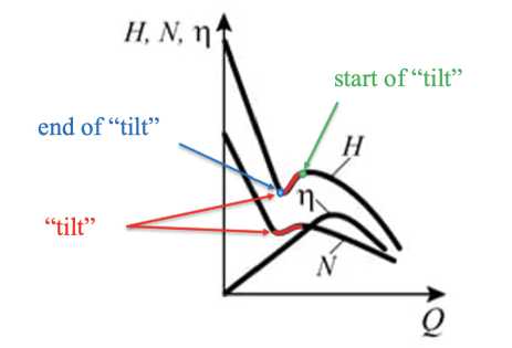
Рис. 1. Форма характеристик осевых насосов с низкой быстроходностью [9]
Fig. 1. Characteristics of axial pumps with low-speed [9]
It is known that the peripheral sections of the interlobe channel of axial impellers are the most pressurised and play an important role in the formation of the drop zone. One of the methods to increase head in this zone is the installation of upper-rotor devices with axial or inclined grooves (J-Grooves) [10; 11] and an inlet guide vane (IGV) with different density [12; 13].
Problem statement and description of the research object
The purpose of the paper is to identify the reasons for the increase of head in the energy drop zone of a low-speed axial pump when upper-rotor devices or inlet guide vanes are installed.
Tasks:
-
1) using numerical computer modelling to obtain head-flow, power and efficiency characteristics of the axial pump;
-
2) to conduct the comparative analysis of the energy characteristics of the axial pump with the installed optimum IGV and J-Grooves with different density of the vane lattice;
-
3) to determine the influence of the installation of the IGV and J-Grooves on the value of reverse flows.
The research object in this paper is a hydraulic turbo pump, which is an axial pump impeller with a vane axial outlet, the working fluid of which is paraffin. The drive of the pump impeller is a hydraulic turbine mounted on a bandage. The pump is designed to pump fuel from the fuel tank to the aircraft engine pump. Similar pump designs are used in the BTPUs of LRDs. Fig. 2 shows a sketch of the research object, where 1 is a rotor; 2 is an axial pump impeller; 3 is a hydraulic turbine; 4 is a nozzle apparatus; 5 is an outlet guide vane; A is an intake of the pump; B is a pump outlet; C is a supply of active working fluid to the working blades of the rotor (turbine 3 ); D is a withdrawal of active working fluid from the working blades of the rotor (turbine 3 ). The main parameters of the axial impeller, outlet guide vane and other parameters of the unit are shown in Table 1 for the maximum efficiency mode. At the inlet of the pump the radial clearance between the rotor and the casing (up to the grid density at the periphery τ ≈ 0.5), the relative value of the radial clearance ∆ rel = 0.023, and further the clearance is equal to 0 because of the installed bandage. The sketch of the studied IGV and J-Grooves is shown in Fig. 3.
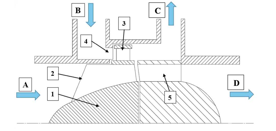
Рис. 2. Эскиз объекта исследования
Fig. 2. Sketch of the research object
To study energy characteristics, the paper considers the variants of an IGV with the number of blades z = 72, 41 and 24 pcs. and the optimum J-Grooves X47L27 (where L is the axial length of the duct, mm, and X is their number, pcs.), which was determined in [10].
In order to reveal the reasons of influence of the installation of the optimum J-Grooves and IGV with different number of blades on the pump head in the zone of pressure drop characteristics the calculation by numerical computer modelling was carried out. The calculation was carried out by solving Reynolds-averaged Navier-Stokes equations in unsteady formulation in the ANSYS CFX software.
The Shear Stress Transport (SST) turbulence model was used in the calculations. The calculation grid was prepared using the ANSYS Mesh for the pump variants without modifications and with J-Grooves , and for the pump variants with the IGV the calculation was carried out using the ANSYS
Mesh + TurboGrid. The final dimensionality is ≈ 36 million cells, and the mean value of the dimensionless distance of the first cell from the wall y+ at significant locations does not exceed 10 in all computational regions, which satisfies the requirements of the selected turbulence model. A part of the grid model is shown in Fig. 4. The y+ distribution fields at the pump rotor are shown in Fig. 5.
A number of geometric and other parameters of the research object
Table 1
|
Name of parameter |
Value |
Units of measurement |
|
Pump speed coefficient, n s |
540 |
– |
|
Maximum unit efficiency |
0.35 |
– |
|
Pump flow rate brought to revolutions at the rated operating conditions, Q/n |
13 |
l/h/rev.∙min |
|
Inlet hub-tip ratio, d 1hub |
0.44 |
– |
|
Outlet hub-tip ratio, d 2hub |
0.65 |
– |
|
Inlet equivalent diameter factor, К De 1 |
4.57 |
– |
|
Outlet equivalent diameter factor, КDe 2 |
3.85 |
– |
|
Angle of attack at mean diameter, i mean |
1.71* |
deg. |
|
Number of blades, z k |
5 |
pcs. |
|
Pump impeller density at mean diameter, τmean |
1.27 |
– |
|
Angle of attack at the input to the outlet guide vane at mean diameter, i 3mean |
4.25 |
deg. |
|
Outlet guide vane density, τOGV mean |
2.08 |
– |
|
Hub-tip ratio of the outlet guide vane, d 1hub OGV |
0.65 |
– |
|
Number of blades of the outlet guide vane, zOGV |
12 |
pcs. |
*
Note : The angles of attack along the height of the blade at other cross-sections differ by about 1 degree.
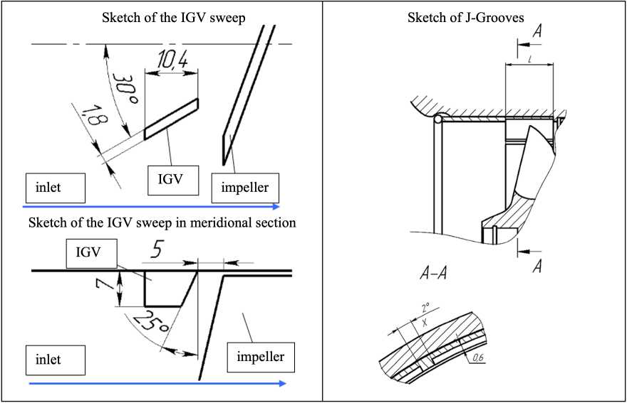
Рис. 3. Эскиз исследованных ВЛУ и НрУ [10; 11; 13]
Fig. 3. Sketch of the investigated IGV and J-Grooves [10; 11; 13]
Without modifications (ANSYS Mesh) J-Grooves X47L27 (ANSYS Mesh)
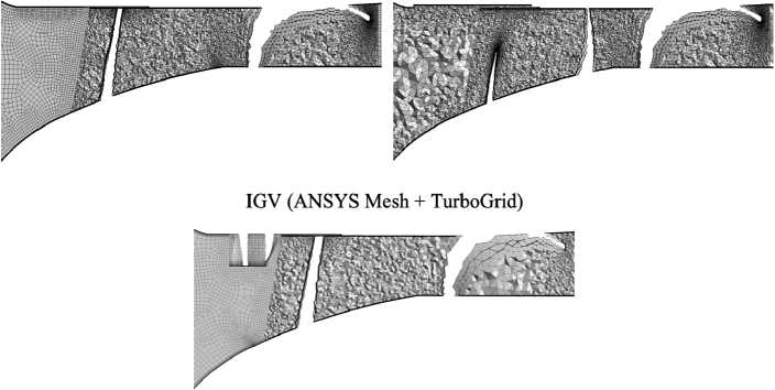
Рис. 4. Сеточная модель в меридиональном сечении
Fig. 4. The grid model in the meridional section
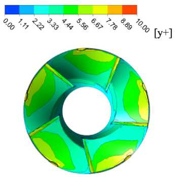
Рис. 5. Поля распределения величины y+ на поверхностях ротора
Fig. 5. y+ distribution fields on rotor surfaces
The following boundary conditions and solver settings were set for the study in the computational regions:
-
1) working fluid of the JET A-1 at a temperature of 25 ºC;
-
2) total inlet pressure (Opening Pres. and Dirn);
-
3) volumetric flow rate of the working fluid at the pump outlet.
The following conditions were made in the calculation model:
-
1) all the walls were specified as smooth (Smooth Wall);
-
2) leakage from the turbine mounted on the bandage was not taken into account;
-
3) heating of the working fluid during pumping was not taken into account.
In order to construct energy characteristics and further analyse them, the static pressure p st was determined by the area averaging method at the cross-sections located at the inlet and outlet of the computational region. The internal power of the pump was determined as follows
N = M rotor ⋅ ω , where Mrotor is a moment from the rotating surfaces of the axial pump, N⋅m; ω is angular speed of rotation, rad/s.
The internal efficiency of the pump was determined as n int: n int = ( A P p • Q ) / N , where ∆p p is static pressure drop at the pump, kgf/cm2.
Validation of the numerical model
To validate the obtained computational models, the universal head-flow characteristics obtained by numerical modelling were compared with the characteristics obtained on the experimental bench in [10; 13]. The results are presented in Fig. 6.
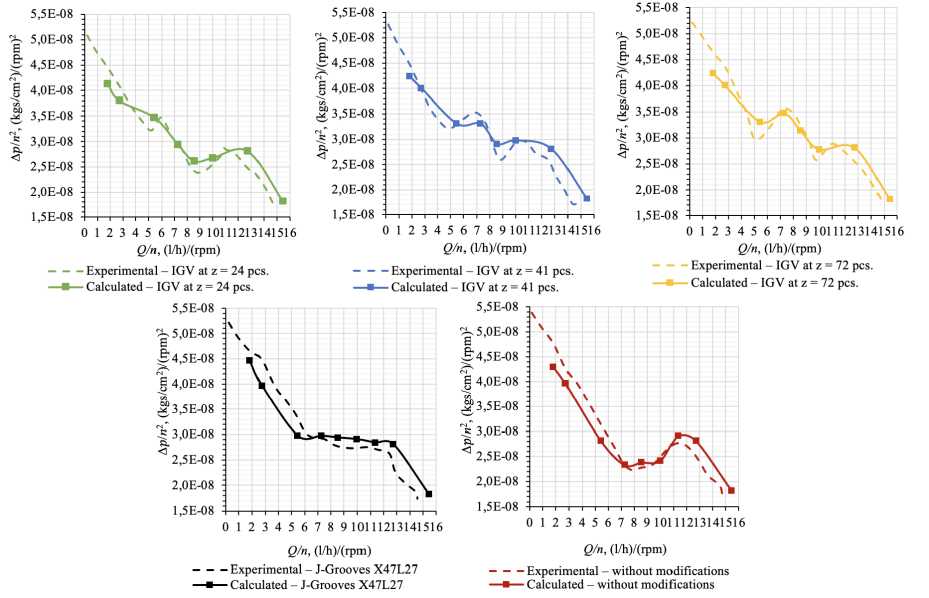
Рис. 6. Валидация расчетных моделей по экспериментальным данным
Fig. 6. Validation of computational models based on experimental data
Based on the obtained characteristics, it can be seen that a good qualitative and quantitative coincidence of the obtained results is achieved; the value of deviations is not more than 8 %. The calculation error is due to the allowance made in the calculation model, and it also depends on the features of the real geometry obtained during production by casting.
Results
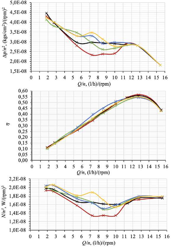
As a result of the calculations performed, the head-flow, power and efficiency characteristics of the pump were obtained. They are shown in Fig. 7.
From the obtained characteristics it can be seen that the installation of the J-Grooves completely eliminates the drop of the head-flow characteristic; and the IGV with different number of blades increases the pump head in the local place of the drop zone. The increase in the differential in the drop zone results in an increase in capacity. In the cases where the optimum J-Grooves or IGV is installed at z = 72 and 24 pcs., the increase in pressure drop is almost the same as the increase in power, resulting in an almost unchanged efficiency. When installing the IGV with 41 blades, the pressure drop increases to a greater extent than the power, which leads to an increase in efficiency by 3-5 % depending on the flow rate in the range from 5 to 11 Q/n.
X Calculated - without modifications X Calculated - J-Grooves X47L27
—X— Calculated - IGV at z = 72 pcs. —* Calculated - IGV at z = 41 pcs.
Calculated - IGV at z - 24 pcs.
Рис. 7. Энергетические характеристики исследованных вариантов насоса, полученные методом численного моделирования
Fig. 7. Energy characteristics of the investigated pump variants obtained by numerical simulation
Installing the optimum J-Grooves does not influence the value of efficiency at its maximum mode, while installing the IGV with different number of blades reduces the maximum efficiency by about 2 %.
The change of power can occur due to the influence of the J-Grooves and IGV on the value and intensity of reverse flows. As it is known, if the value of the reverse flows twist is reduced or eliminated, the moment on the axial wheel shaft М h will increase by the magnitude of the moment of motion of the reverse flows. The increase of the moment М h will also occur due to the increase of the moment of friction forces of reverse flows М fr, at installation of various vane grids in the inlet branch, as well as at the complex configuration of the branch [5].
In order to study the effect on the reverse flows, the length of the reverse flow zone was determined using cross-sections that are located in the inlet line at different distances from the inlet edge of the pump impeller blades. Fig. 8 shows a visual representation of the method of determining the length when processing the calculation results, showing the volume of the reverse flow, as well as the crosssections themselves, whose area is equal to the area of the reverse flow. This method allows determin- ing with sufficient accuracy the beginning of the formation of reverse flows at the inlet of the axial impeller of the pump.
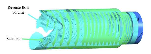
Рис. 8. Метод определения длины распространения обратных токов
-
Fig. 8. Method for determining the propagation length of the reverse flow
The Russian scientists V. I. Petrov and V. F. Chebaevskiy conducted an experimental study of the reverse flow zone propagation in the pump inlet line. To determine the distance to which the reverse flow zone propagates from the inlet edges, they used a method based on the deviation of the position of flexible silk threads that were glued along the length of the transparent part of the pump inlet line [5].
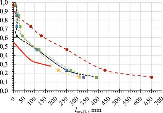
To evaluate the influence of the IGV and optimal J-Grooves on the reverse flow propagation length, Fig. 9 shows a graph of the dependence of the flow parameter at the inlet q 1 on the propagation length of the reverse flow zone l rev.fl in comparison with the experimental data obtained by V. I. Petrov and V. F. Chebaevskiy for a screw with a density of 1.44 and a constant bushing ratio equal to 0.44. F. Chebaevsky for a screw with a density of 1.2 and a constant hub-tip ratio of 0.44.
• - Calculated - without modifications
-k — Calculated - J-Grooves X47L27
Calculated - IGV at z = 72 pcs.
•*••• Calculated - IGV at z = 41 pcs.
•*•• Calculated - IGV at z = 24 pcs.
-----Experimental results of V.I. Petrov and Vf. Chebae vskiy
Рис. 9. График влияния установки ВЛУ и НрУ на длину распространения зоны обратных токов [5]
-
Fig. 9. The effect of the IGV and J-Grooves installation on the propagation length of the reverse flow zone
Fig. 9 shows that the experimental data have qualitative coincidence with the shape of the pump curve without modifications, obtained by numerical modelling. Quantitative differences are caused by the difference in geometrical parameters of the research objects themselves, as well as in the methods of research.
In order to fully assess the influence of the installation of the J-Grooves and IGV on the reverse flows, Fig. 10 shows the dependence of the relative area of the reverse flows on the flow parameter q 1 of the pump variant without modifications in comparison with the experimental results of V. I. Petrov and V. F. Chebaevskiy as well as with the results of the studies of French scientists, where S rev.fl is the area of the reverse flow, S in is the area of the inlet cross-section of the pump.
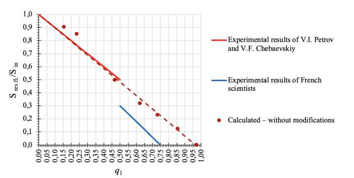
Рис. 10. Зависимость относительных площадей зон обратных токов и активного потока от параметра q 1 в сравнении с экспериментальными данными [14: 15]
-
Fig. 10. Dependence of the relative areas of the reverse and active flow zones on the q 1 parameter in comparison with experimental data [14; 15]
The averaged experimental dependences of V. I. Petrov and V. В. F. Chebaevsky shown in Fig. 10 were obtained by them on the basis of processing the results of measuring velocity fields at the inlet of various axial, diagonal and centrifugal impellers [14]. The technique of obtaining the area of the reverse flow was applied with the allowance, the boundary of the back and reverse flow was taken as a circle, and the minimum distance from the measurements to the inlet edge of the blades was 1 diameter of the inlet manifold, because of which the graph breaks at q 1 = 0.5.
French scientists extended the line of the Russian researchers by applying the method of photofixation to obtain areas. This method more accurately reflects the boundary of back and reverse flow, but the study was carried out at developed cavitation, and, as is known, cavitation phenomena in reverse flows can affect their value and, therefore, the data from the source [15] are below.
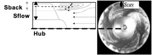
Рис. 11. Метод определения площади обратного течения французскими учеными [15]
Fig. 11. The method of determining the area of the reverse flow by French scientists [15]
Fig. 10 shows that the data obtained by numerical modelling correlate well with the data obtained in [14]; the calculated data of the pump variant without modifications have a good qualitative and quantitative coincidence with the results of experimental studies of the Russian scientists. The value of deviations at low flow rates (at q1 < 0.25) is not more than 7 %, and at flow rates at q1 > 0.25 the deviations are not more than 3 %. Due to the numerical method of the study, it was possible to extend the line obtained in [14].
Fig. 12 shows the dependence of the relative areas of the reverse flow zones on the parameter q 1 in comparison for all investigated variants of the IGV and optimal J-Grooves. It can be seen that the installation of the IGV and J-Grooves does not affect the beginning of formation of reverse flows; they are formed similarly to the pump variant without modifications at q 1< 0.97.
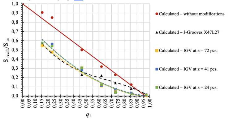
Рис. 12. Зависимость относительных площадей зон обратных токов и активного потока от параметра q 1 в сравнении с ВЛУ и НрУ
Fig. 12. The dependence of the relative areas of the reverse and active flow zones on the q 1 parameter in comparison with the IGV and J-Grooves
Fig. 12 shows that installation of the IGV and J-Grooves reduces the value of S rev.fl (starting from q 1 = 0.85) compared to the pump variant without modifications. This is explained by the fact that the installation of the J-Grooves or IGV reduces the value and intensity of inlet reverse flows, which, in turn, is one of the reasons for the increase of the axial pump head in the drop zone of the head characteristic.
Conclusion
The following conclusions can be drawn as a result of the study carried out by the numerical modelling method:
-
1. The increase of the differential drop in the head characteristic drop zone is accompanied by an increase of the pump power, which in turn is changed due to the influence of the J-Grooves or IGV on the value and intensity of the reverse flows, as well as due to the increase of the friction moment Mfr of the reverse flows when different J-Grooves or IGV are installed in the inlet pipe.
-
2. The installation of the J-Grooves or IGV leads to a reduction in the value and intensity of inlet reverse flows with the reduction in the flow parameter q 1< 0.85.
-
3. The optimal geometry of the J-Grooves does not affect the maximum efficiency of the pump, while the installation of the IGV with different number of blades reduces the maximum efficiency by about 2 %.
On the basis of this study, it can be concluded that for multi-mode pumps, it is preferable to use J-Grooves, as its installation completely eliminates a head loss. The use of IGVs is possible to increase the pump head in the local zone. Reducing the value of reverse flows can contribute to the reduction of vibration and pressure pulsations and, as a consequence, improve the reliability and service life of the units of the supply system.
