Comparative analysis of methods for regulating the frequency characteristics of simulators of electrical characteristics of spacecraft power supply systems

Author: Mizrakh E.A., Lobanov D.K., Kharlashina S.V.
Journal: Siberian Aerospace Journal @vestnik-sibsau-en
Section: Aviation and spacecraft engineering
Article in issue: 3 vol.25, 2024.
Free access
One of the main systems of a spacecraft (SC) is a power supply system (PSS). The basis of a PSS are secondary power sources (SPSs), which use various methods of controlling and converting electricity, which leads to significant differences in their dynamic properties. On the onboard consumer side, the dynamics of the PSS is determined by the total internal resistance (impedance) of the SPSs. When conducting ground electrical tests of spacecraft EES (electrical engineering systems), due to the complexity of using power supply systems, test complexes are used, the basis of which is simulators of electrical characteristics of the PSS (PSSS). Modern PSSSs use a modular configuration principle, which makes it possible to produce PSSSs of different powers, but energy modules have fixed or adjustable impedance frequency response over a narrow frequency range, which leads to the limitation of the types of PSS being simulated. Equipping the PSSS with the property of regulating frequency response in a wide frequency range expands the functionality of the PSSS, as it allows simulating the dynamic properties of the PSS containing different types of SPSs. The purpose of the work is to study and carry out the comparative analysis of three methods for regulating the impedance frequency response (IFR) of the PSSS module. The methods for regulating the frequency response of a PSSS are being considered on the basis of its generalized functional diagram containing mathematical models: adder amplifier (AA), feedforward compensator (FC), power amplifier (PA), voltage divider (VD) and load (L). The article analyzes options for regulating the impedance frequency response of PSSS, and considers three methods for regulating the IFR: two with a passive FC and one with an active FC. The paper presents a simulation model in the MicroCap package of the electrical circuit of the PSSS module, and computational experiments have been carried out on each method of regulating the IFR of the PSSS. Based on the results of the study, a method for correcting and regulating the IFR of the PSSS is recommended, which makes it possible to separately regulate the low-frequency and mid-frequency regions of the IFR, which allows us to significantly simplify the configuration and provision of the IFR of the PSSS in accordance with the specified requirements.
Power supply system, simulator, impedance, frequency response, regulation, modeling
Short address: https://sciup.org/148329747
IDR: 148329747 | UDC: 681.333.(088.8) | DOI: 10.31772/2712-8970-2024-25-3-337-350
Text of the scientific article Comparative analysis of methods for regulating the frequency characteristics of simulators of electrical characteristics of spacecraft power supply systems
One of the main systems of a spacecraft (SC) is a power supply system (PSS) [1–3]. Secondary power sources (SPSs) are the basis of the PSS, using different methods of control and power conversion [4–7], which leads to significant differences in their dynamic properties. On the side of onboard consumers, the dynamics of the PSS is determined by the total internal impedance of the SPSs.
During ground tests, the consumers being connected to the spacecraft PSS shall be checked for operability and resistance to electromagnetic interference of permissible amplitude (GOST R51317.4.112007).
The onboard PSS in this case does not meet the test conditions for the following reasons:
-
– to simulate the deterioration of the supply voltage quality due to emergency modes and gradual degradation of the electrical equipment of the onboard PSS, it is required to vary the voltage in a wide range at the inputs of consumers (loads);
-
– the spacecraft PSS cannot reproduce interference on the power buses with specified parameters, which does not allow simulating the interference situation and testing the performance and resistance to electromagnetic interference of permissible amplitude of spacecraft electrical engineering systems (EESs), such as repeaters, on the power buses;
-
– it is better to avoid using spacecraft onboard PSSs during the input control of electrical equipment of energy consumers due to the possibility of abnormal situations or failures of the equipment being tested, which may lead to failure of low-power consumers.
During ground electrical tests of spacecraft EES, due to the complexity of power supply systems, automated test complexes are used [8–11], which include simulators of the electrical characteristics of the main PSS subsystems, including power supply systems simulators (PSSSs).
Modern PSSSs [12; 13] use a modular principle of configuration, which allows to produce PSSSs of different power, but power modules have fixed or adjustable in a narrow frequency range impedance frequency response, which leads to the limitation of types of simulated PSSs. Providing PSSSs with the property of frequency response regulation in a wide range of frequencies expands their functionality, as it allows simulating the dynamic properties of different types of PSSs.
The aim of the work is to study and and conduct the comparative analysis of three methods of impedance frequency response (IFR) regulation of the PSSS module, which was developed by the authors.
Methods of solving the problem
The ways of regulating the IFR of the PSSS are considered on the basis of its generalised functional scheme (Fig. 1), containing mathematical models of the adder amplifier (AA), feedforward compensator (FC), power amplifier (PA), voltage divider (VD) and load (L).
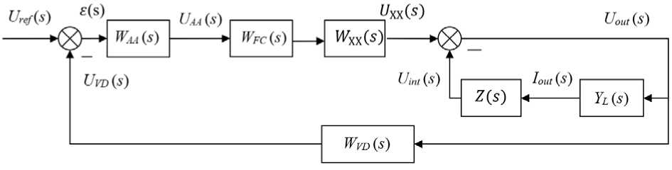
Рис. 1. Функциональная схема модуля ИСЭП:
W УС ( s ) – передаточная функция (ПФ) усилителя-сумматора; W КУ ( s ) – ПФ корректирующего устройства (КУ), обеспечивающего устойчивость и требуемое качество переходных процессов системы управления ИСЭП;
W Д Н( s ) – ПФ цепи обратной связи; W ХХ( s ) – ПФ УМ в режиме холостого хода; Z ( s ) – внутренний импеданс УМ;
Y Н ( s ) – адмитанс нагрузки
-
Fig. 1. Functional diagram of the PSSS module:
W AA ( s ) – transfer function (TF) of the adder amplifier (AA); W FC ( s ) – TF of the feedforward compensator (FC), ensuring stability and the required quality of transient processes of the PSSS control system; W VD ( s ) – TF of a feedback circuit;
W ХХ ( s ) – PF of the PA in idle mode; Z ( s ) – internal impedance of the PA; Y L ( s ) – load admittance
PSSS impedance is described using the following expression:
Z PSSS ( s )
Uout ( s ) lout ( s )
Z (s)
1 + W p ( s ) )
where TF of W Р ( s ) is the TF of the open loop of the PSSS, according to Fig. 1, at excluded Y L ( s ) has the following form
W p ( s ) = W aa ( s ) • W fc ( s ) • W xx ( s ) ' W vd ( s ) . (2)
Turning to the impedance frequency response (IFR), we obtain for the IFR of the PSSS:
Z PSSS
(w) =
Z (ja)
1 + W p ( j ® )
Z ( a )1—— ’ 1 + W p ( j a )
In the low frequency (LF) region at ω → 0, in order to ensure the required accuracy of stabilisation of the output voltage U out , the static loop gain is much greater than 1, i.e. the condition ǀ W P ( j 0)ǀ » 1 is satisfied, therefore we can write:
Z psss ( « ) - Z ( a )
Wp (j0)
Since the adjustment of the internal impedance Z(ω) of the PA is difficult, and often impossible, it follows from (4) that the adjustment of the active part of the PSSS impedance frequency response Z PSSS (ω) in the low-frequency region is possible only due to the static gain W P ( j 0).
In the high frequency (HF) region at ω → ∞, in order to ensure the required filtering properties of the PSSS, the condition: ǀ W P (ω)ǀ « 1 is satisfied, therefore we can write:
Z PSSS ( w ) Z ( M ) '
1 + Wp (>)
~ Z ( a ) ,
since the impedance frequency response of PSSS (5) in the HF region coincides with the impedance frequency response of the PA, it cannot be controlled.
In the mid-frequency (MF) region, where the TF modulus W P (ω) of the open loop is commensurable with 1, the control of the IFR Z PSS (ω) (ω) is possible mainly by changing the parameters of the FC TF W FC ( s ), which, according to (2), is included in the W P (ω) expression.
Let us consider three methods to regulate the low- and mid-frequency IFR of the PSSS.
Fig. 2 shows a simulation model in MicroCap package of the electrical circuit of the PSSS module with a passive correction device containing resistors R FC1 , R FC2 and capacitor С 1 . Fig. 3 shows the frequency response data of the open loop of the corrected system corresponding to (2).
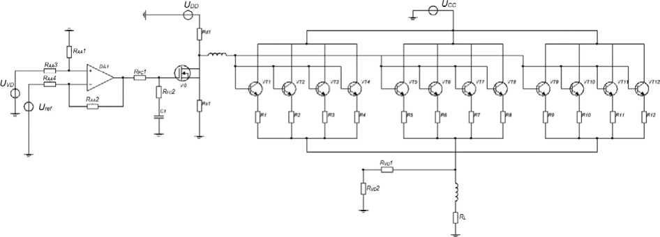
Рис. 2. Имитационная модель разомкнутого контура скорректированной системы управления модуля ИСЭП
-
Fig. 2. The open-loop simulation model of the adjusted control system of the PSSS module
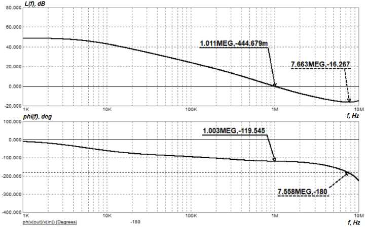
Рис. 3. ЛЧХ разомкнутой скорректированной системы управления модуля ИСЭП
-
Fig. 3. The LFC of the open-loop adjusted control system of the PSSS module
The system is stable. It complies with stability margin and bandwidth requirements.
The first method to regulate the IFR of the PSSS consists in changing the AA transmission gain by means of the R AA 2 resistor and changing the FC parameters by means of the R FC 1 resistor [14].
The TF of the AA has the following form
W aa ( s ) =
UAA ( s ) UVD ( s )
WOA ( S)
R AA4
R AA4 + R AA2
,
• W OA ( S ) + 1
where W OA (s) is a TF of an open operational amplifier.
The TF of the FC, according to the electrical diagram (Fig. 2), is
W FC ( S )
R FC2 • C 1 • s + 1
( R FC1 +R FC2 ) • C 1 • s + 1
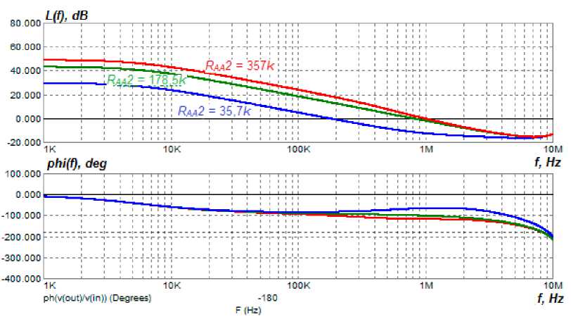
Рис. 4. ЛЧХ скоректированной системы управления модуля ИСЭП при изменении сопротивления R УС2
Fig. 4. The LFC of the adjusted control system of the PSSS module when changing the R AA 2 resistance
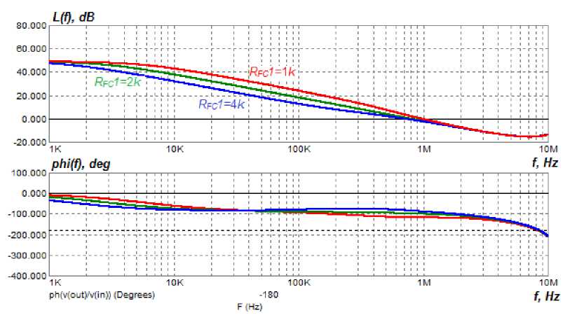
Рис. 5. ЛЧХ скоректированной системы управления модуля ИСЭП при изменении сопротивления R КУ1 (способ 1)
-
Fig. 5. The LFC of the adjusted control system of the PSSS module when changing the R FC1 resistance (method 1)
The analysis of the LFC (Fig. 4 and 5) of the open-loop control system of the PSSS module with varying resistances of resistors shows that the system remains stable at changing the resistance ratings, the cut-off frequency and phase margin do not change significantly.
The IFR of the PSSS measured on the simulation model (Fig. 2) according to (3), with the variation of the resistances of the same resistors in similar ranges as in the previous case, are shown in Fig. 6 and 7.
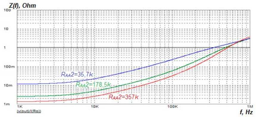
Рис. 6. ИЧХ замкнутой системы управления модуля ИСЭП при изменении сопротивления R УС2 (способ 1)
-
Fig. 6. The IFR of the closed-loop control system of the PSSS module when changing resistance R AA 2 (method 1)
The increase of the feedback RAA2 resistance (see Fig. 6) leads to increase of the AA gain and increase of its time constant. As a result, all this leads to decrease of the active component of the IFR of the PSSS in the low-frequency region and deformation of the inductive component of the IFR in the mid-frequency region.
From Fig. 7 it can be seen that when changing the R FC 1 resistance, the active component of the IFR of the PSSS remains constant, and only the mid-frequency (MF) region of the IFR is regulated.
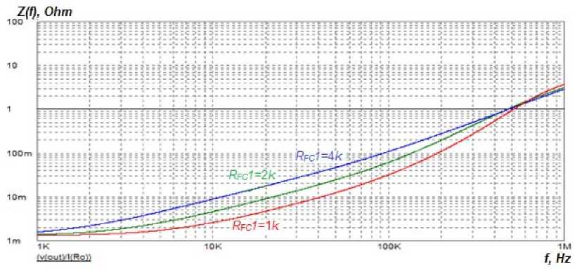
Рис. 7. ИЧХ замкнутой системы управления модуля ИСЭП при изменении сопротивления R КУ1 (способ 1)
-
Fig. 7. The IFR of the closed-loop control system of the PSSS module when changing the R FC 1 resistance (method 1)
Thus, it is possible to recommend the following procedure of providing the required parameters of the IFR of the PSSS: a) by choosing the value of feedback resistance R AA 2 the required value of the active component of the IFR of the PSSS is provided; b) by choosing the value of resistance R FC 1 the required type of IFR in the mid-frequency (MF) region is provided.
The disadvantage of this method is that when changing the feedback resistance R AA 2, the MF region of the IFR is deformed, which complicates the selection of the value of resistance R FC 1 of the FC.
The second method to regulate the IFR of the PSSS [15] also consists in changing the AA transmission gain by means of the R AA 2 resistor and changing the FC parameters by means of the R FC 1 resistor, but differs in the electrical scheme of connecting the FC and the AA. In this case, the negative feedback in the AA is initiated not from the AA output, but from the output of the FC (Fig. 8), i.e. the FC enters the control loop of the OA, forming a second-type FC. The simulation model of the open loop of the corrected control system of the PSSS module differs from Fig. 2 in that the OA and the FC are replaced by the scheme of the second-type FC (Fig. 8).
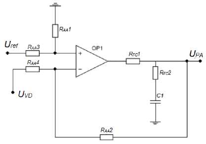
Рис. 8. Электрическая схема КУ второго типа
Fig. 8. The electrical diagram of the second type FC
Transfer function of the second type FC scheme:
WFC ( s )
UPA ( s ) UVD ( s )
^^^^^^^
WOA ( S )'
R FC2 ' C 1 ' s + 1
( R FC1 + R FC2 ) ' C 1 ' s + 1
____ R AA4 ' W ( s ) ' R FC2 ' C 1 ' s + 1
R AA4 + R AA2 ( R FC1 + R FC2 ) ' C 1 ' s + 1
where W OA ( s ) is a TF of an open loop operating amplifier.
To match the LFC of the corrected system with the LFC of the previous case, the capacitance of the С 1 capacitor was recalculated. The values of resistances of the resistors remained unchanged.
The results of measuring the LFC of the open loop system when the feedback R AA 2 resistance and the R FC 1 resistance are changed are shown in Fig. 9 and 10, respectively.
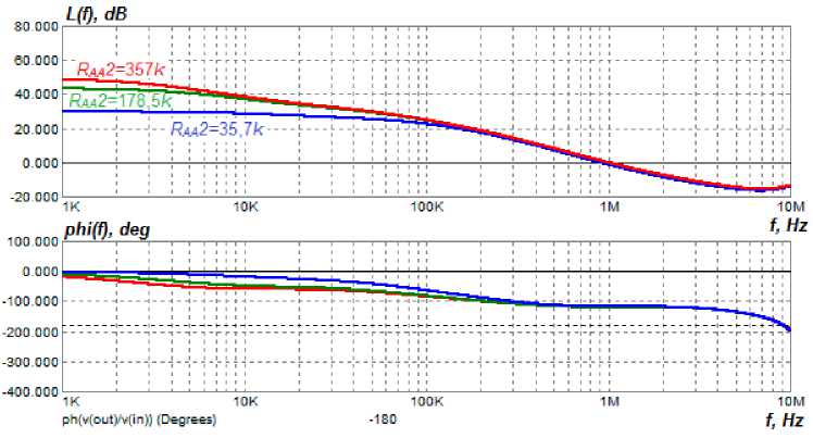
Рис. 9. ЛЧХ скоректированной системы управления модуля ИСЭП при изменении сопротивления R УС2 (способ 2)
Fig. 9. The LFC of the adjusted control system of the PSSS module when changing the R AA 2 resistance (method 2)
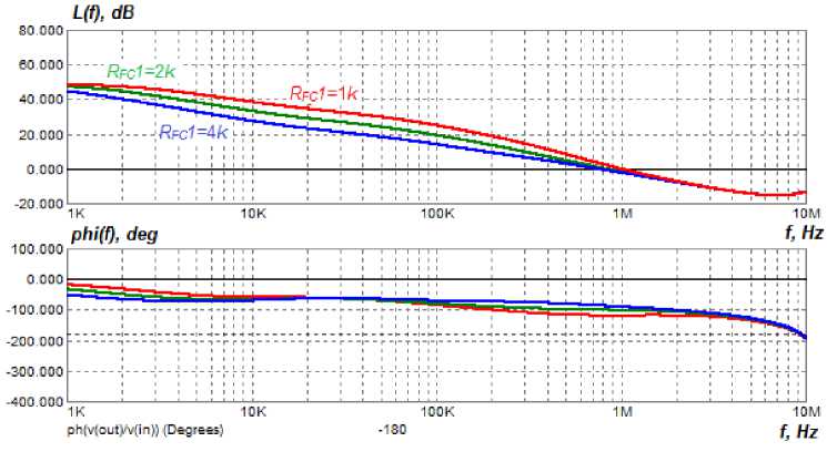
Рис. 10. ЛЧХ скоректированной системы управления модуля ИСЭП при изменении сопротивления R КУ 1 (способ 2)
Fig. 10. The LFC of the adjusted control system of the PSSS module when changing the R FC1 resistance (method 2)
Fig. 9 and 10 show that the control system remains stable when the resistance values are changed, and the cut-off frequency and phase margin change insignificantly.
The IFR of the PSSS measured on the simulation model with the correction made according to the second method at variation of resistances of the same resistors in the similar ranges as in in the previous case, are shown in Fig. 11 and 12.
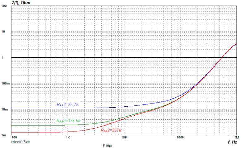
Рис. 11. ИЧХ замкнутой системы управления модуля ИСЭП при изменении сопротивления R УС2 (способ 2)
Fig. 11. The IFR of the closed-loop control system of the PSSS module when changing the RAA2 resistance (method 2)
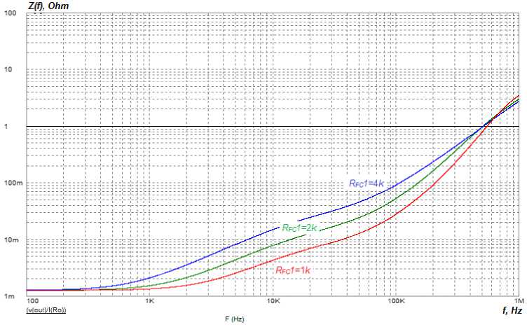
Рис. 12. ИЧХ замкнутой системы управления модуля ИСЭП при изменении сопротивления R КУ1 (способ 2)
Fig. 12. The IFR of the closed-loop control system of the PSSS module when changing the R FC1 resistance (method 2)
Fig. 11 shows that increasing the R AA 2 resistance decreases the active component of the IFR of the PSSS, while the inductive component remains practically unchanged. Fig. 12 shows that varying the R FC 1 resistance changes the mid-frequency region of the IFR and keeps constant the active component of the IFR.
Conclusion: in this method it is possible to independently regulate the low-frequency and midfrequency regions of the IFR of the PSSS by varying the value of the R AA 2 resistance and R FC 1 resistance, respectively.
The third method of regulating the IFR of the PSSS is based on changing the R FC 1 and R AA 2 resistances of the third type of the AA – active, made on the summing operational amplifier (Fig. 13).
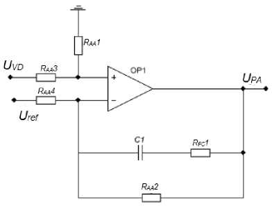
Рис. 13. Электрическая схема КУ третьего типа
Fig. 13. The electrical diagram of the third type FC
The transfer function of the scheme is:
W fc ( s ) = U PA
U OA
R AA2 R FC1 ‘ C 1 ‘ S + 1
---------------------------------------------------------------:----------------------------------------------.
R AA4 ( R FC1 +R AA2 ) ‘ C 1 ' S + 1
The FC parameters are calculated in such a way that the logarithmic gain of the FC of the first and third type coincide, and the values of the R AA 1 and R AA 2 resistances remain unchanged.
The IFR of the PSSS measured on the simulation model with the correction made by the third method, with the variation of the resistances of the same resistors in similar ranges as in the previous cases, are shown in Fig. 14 and 15.
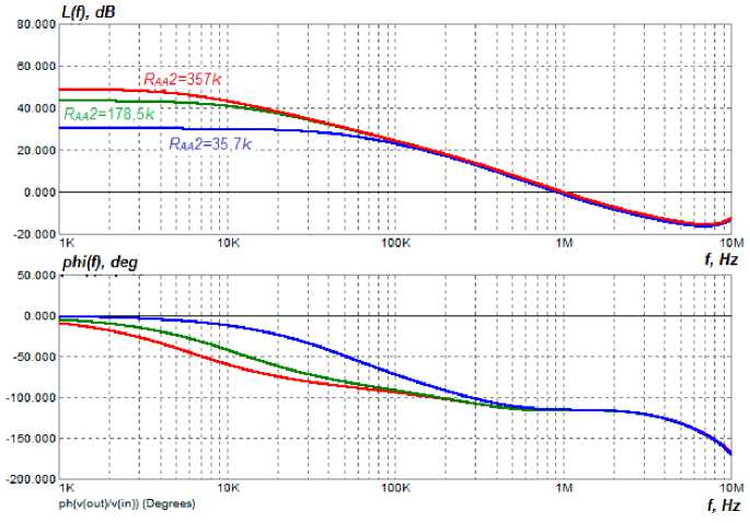
Рис. 14. ЛЧХ скоректированной системы управления модуля ИСЭП при изменении сопротивления R УС2 (способ 3)
Fig. 14. LFC of the adjusted control system of the PSSS module when changing the R AA 2 resistance (method 3)
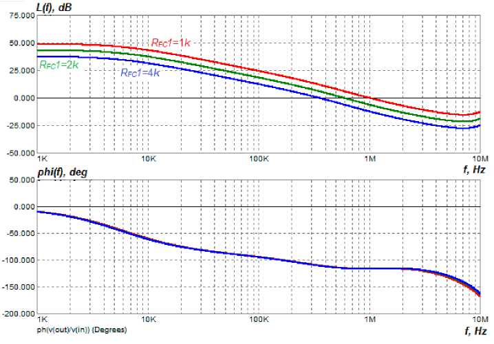
Рис. 15. ЛЧХ скоректированной системы управления модуля ИСЭП при изменении сопротивления R КУ 1 (способ 3)
Fig. 15. The LFC of the adjusted control system of the PSSS module when changing the R FC 1 resistance (method 3)
Fig. 14 and 15 show that the control system remains stable when the impedance values are changed, and the cut-off frequency and phase margin change only slightly.
The IFR of the PSSS measured on the simulation model according to (3), when the R AA 2 and R FC 1 resistances of resistors are varied in similar ranges as in the previous cases, are shown in Fig. 16 and 17.
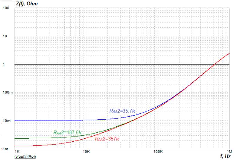
Рис. 16. ИЧХ замкнутой системы управления модуля ИСЭП при изменении сопротивления R УС2 (способ 3)
Fig. 16. The IFR of the closed-loop control system of the PSSS module when changing the R AA 2 resistance (method 3)
It can be seen from Fig. 16 that varying the feedback R AA 2 resistance of the OA changes the active component of the IFR of the PSSS without changing the inductive component of the IFR.
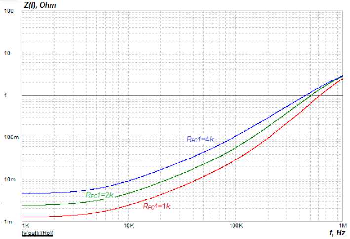
Рис. 17. ИЧХ замкнутой системы управления модуля ИСЭП при изменении сопротивления R КУ1 (способ 3)
Fig. 17. The IFR of the closed-loop control system of the PSSS module when changing the R FC1 resistance (method 3)
When varying the R FC 1 resistance of the FC, the active and inductive components of the IFR are changed simultaneously, which complicates the control of the IFR of the PSSS.
Conclusion
The comparative analysis of the results of simulation modelling of three methods of correction and regulation of the IFR of the PSSS has shown:
-
1. All three methods make it possible to adjust the IFR of the PSSS in the low-frequency and midfrequency region of the IFR without deteriorating the stability of the PSSS control system.
-
2. For practical application it is necessary to recommend the second method of correction and regulation of the IFR of the PSSS, which allows us to regulate separately the low-frequency and mediumfrequency regions of the IFR, that makes it possible to simplify considerably the adjustment of the IFR of the PSSS in accordance with the given requirements.
References Comparative analysis of methods for regulating the frequency characteristics of simulators of electrical characteristics of spacecraft power supply systems
- Soustin B. P., Ivanchura V. I., Chernyshev A. I., Islyaev Sh. N. [Power supply systems for spacecraft]. Novosibirsk, Nauka Publ., 1994, 318 p.
- Qi Chen, Zhigang Liu, Xiaofeng Zhang, Liying Zhu. Spacecraft Power System Technologies. Springer. 2020. 321 p.
- Gruzdev A. I., Pushko S. V., Shevtsov M. S. [Innovative approaches to the design of power supply systems for low-orbit spacecraft with an active life of 7 years or more]. Issue. Electromech. 2022, No. 2, P. 24–33 (In Russ.).
- Krasnobaev Yu. V. [Methodology for the synthesis of laws and structures of converter control devices, Yu. V. Krasnobaev]. Universities Instrumentation. 2004, Vol. 47, No. 4, P. 39–48 (In Russ.).
- Krasnobaev Yu. V. [Prospects for the development of charge-discharge devices for power supply systems for spacecraft]. Siberian Aerospace Journal. 2024, Vol. 25, No. 1, P. 115–125. Doi: 10.31772/2712-8970-2024-25-1-115-125.
- Fernandez-Serantes, Luis-Alfonso; Casteleiro-Roca, José-Luis. Data dimensionality reduction for an optimal switching mode classification applied to a step-down power converter. Logic Journal of the IGPL, 2024. Available at: https://doi.org/10.1093/jigpal/jzae036.
- Eraydin H., Bakan A. F. Efficiency comparison of asynchronous and synchronous buck converter. In 2020 6th International Conference on Electric Power and Energy Conversion Systems (EPECS). 2020, P. 30–33.
- Mizrakh E. A., Balakirev R. V., Lobanov D. K., Fedchenko A. S., Shtabel N. V. Kompleks dlya nazemnykh ispytaniy sistem elektropitaniya kosmicheskikh apparatov [Complex for ground testing of spacecraft power supply systems]. Patent RF, No. 154432. 2015 (In Russ.).
- Mizrakh E. A., Balakirev R. V., Lobanov D. K., Tkachev S. B., Fedchenko A. S. Kompleks dlya nazemnykh ispytaniy sistem elektropitaniya kosmicheskikh apparatov [Complex for ground testing of spacecraft power supply systems]. Patent RF, No. 159208. 2016 (In Russ.).
- Mizrah E. A., Lobanov D. K., Kopylov E. A., Balakirev R. V., Fedchenko A. S. On the Static Accuracy of Charge-Discharge Units Intended for Electrical Tests of High Capacity Li-ion Batteries. IOP. 2017, No. 255, P. 012016.
- Kopylov E. A., Lobanov D. K., Mizrah E. A. [Control process absolute stability analysis of charge-discharge device with load converter in constant power mode]. Siberian Journal of Science and Technology. 2018, Vol. 19, No. 2, P. 281–292 (In Russ.).
- Mizrach E. A., Poimanov D. N., Balakirev R. V. et al. [Automated system for simulating electrical characteristics of spacecraft power supply systems]. Siberian Journal of Science and Technology. 2016, Vol. 17, No. 3, P. 702–709 (In Russ.).
- Lobanov D. K., Mizrah E. A., Samotik L. A., Tkachev S. B., Shtabel N. V. [Energy saving simulation test complex for spacecraft power supplies full-scale electrical tests]. Siberian Journal of Science and Technology. 2020, Vol. 21, No. 3, P. 400–408 (In Russ.). Doi: 10.31772/2587-6066-2020-21-3-400-408.
- Mizrakh E. A., Solodilov I. P. Regulation of the output impedance of a specialized power supply via a control circuit. Materials of the XX International Scientific Conference of Bachelors, Masters, Postgraduate Students and Young Scientists. Krasnoyarsk, 2021, P. 379–381 (In Russ.).
- Mizrakh E. A., Solodilov I. P. A device for regulating the output impedance of a specialized power supply. Reshetnevsky readings. Materials of the XXV International scientific-practical conference, Siberian State University named after. M. F. Reshetneva. 2021, Part 1, P. 386–389.
