Comparative analysis of phase-lock control system algorithms for spread-spectrum signal receiver

Author: Kuzmin Evgeny V.
Journal: Журнал Сибирского федерального университета. Серия: Техника и технологии @technologies-sfu
Article in issue: 1 т.4, 2011.
Free access
This paper investigates noise-immunity of phase-lock control system for spread-spectrum minimum shift keying signal receiver in case of adjacent channel interference influence. Four algorithms of phase-lock control system are suggested and described. Statistic simulations of signal processing in involved system are given.
Spread-spectrum signal, minimum shift keying, phase synchronization system, statistical modeling, signal from adjacent channel, comparative analysis
Short address: https://sciup.org/146114562
IDR: 146114562 | UDC: 621.384
Сравнительный анализ алгоритмов слежения за фазой шумоподобного сигнала
В статье исследуется помехоустойчивость системы фазовой синхронизации приёмника шумоподобного сигнала с минимальной частотной манипуляцией при воздействии структурно-подобной помехи. Предложены и описаны четыре алгоритма слежения за фазой шумоподобного сигнала с минимальной частотной манипуляцией. Представлены результаты статистического моделирования рассматриваемой системы.
Text of the scientific article Comparative analysis of phase-lock control system algorithms for spread-spectrum signal receiver
Spread spectrum signals with minimum shift keying (MSK) are widely used in modern radio navigation systems (RNS). Serviceability on long distances D max ≈ 1000 km makes a demand to RNS, to have rather large value of receiver’s dynamic range (more than 80 dB ). High accuracy of coordinate measuring in all working area of RNS, requires investigating algorithms of phase-lock control system of MSK-signal receiver, which provides phase shift measurements with root-meansquare (RMS) error оф< 3 ° , then signal-to-noise ratio threshold equals to - 40 dB (in the band of MSK-signal) and in case of adjacent channel interference influence (disturbing signal from another radio-range beacon) [1].
The aim of this article: noise-immunity investigation for suggested algorithms of phase-lock control system for MSK-signal receiver in case of adjacent channel interference influence.
Describing and comparative analysis of phase-lock control system algorithms results
Total realization of MSK-signal, signal from adjacent channel (SAC) and additive white Gaussian noise (AWGN) can be described as [2, 3]:
y ( t ) = S ( t — T s ) + Y S / ( t -t S ) + ^ ( t ) ,
s ( t -T J = Re {- S '( t -T s ) exp[ j ( 2 n( f 0 ± F d ) t -Ф s ) ] } ,
here s ( t - т s ) and s ( t -t , ) are MSK-signal and SAC with delays т s and t s accordingly; y = PP, /P s -ratio «SAC/signal», P s and P s - powers of signal and SAC accordingly; £( t ) - AWGN; f 0 - carrier frequency; Fd - frequency Doppler shift; ф s - starting phase of signal; S ( t -t s ) - complex envelope of MSK-signal:
-S ' ( t T s ) = D ( t T s ) ^|2P s exp [ j 0 ( t T s ) ] , (2)
where D ( t - т s ) = ±1 - the information signal imposed on navigation signals for information transfer
t about differential corrections for GNSS users; 9(t) = — f d(t')dt' - function, which determines angle 2T 0
N -1
modulation, d ( t ) = ^ dt rect( t - iT ), { d i } - pseudorandom sequence (PRS) of N -length, T - one’s bit i =0
PRS duration, rect( t ) – square pulse with T duration. Disturbing signal from adjacent channel has similarly mathematics description, and different parameters (including information signal D / ( t - t , )).
Digital phase-lock control system (PLCS) structure chart of MSK-signal receiver is presented on Fig. 1. Values y i = y ( t i ) ( t i = i Д t , i = 0,1,..., д t - sampling interval) are incoming observations to digital phase-shift discriminator (DPD), which comes from an exit of analog-digital converter (ADC) [1, 4].
Reference signals of carrier frequency is cos Ф i ( k ) = cos(2 n( f 0 ± F d ( k )) t i ) and sin Ф i ( k ) = cos(2 n( f 0 ± F d ( k )) t i ) come into supporting inputs of DPD. These signals are formed by digital synthesizer (DS) and based on frequency Doppler shift estimation F ˆ d ( k ) in each k -period of filtering. Reference signals Q i = sin 9 i and I i = cos 9 i , which are synchronous with quadrature components of MSK-signal, formed by delay lock system. Quadrature components of bandwidth compressing signal (after MSK-detection) are formed by summarizing of multiplications of quadrature components of realization (1) and reference signals Ii , Qi and integration on intervals t e[ kT p ,( k +1) T p ], k = 0,1,..., ( T p - MSK-signal’s period). Time of one cycle radio-range beacon transmition equals T c = 25 Tp . Error signal which is proportion to phase mismatch forms in compliance with algorithm:
Z d ( k ) = sign ( z 1 ( k ) ) z 2 ( k ) = D ( k ) z 2 ( k ) , (3)
where sign ( x ) - sign function, D ( k ) - estimation ofinformation signal D ( t -t s ) on k -period offiltering, z 1 ( k ) and z 2( k ) - quadrature components of correlation, computing on interval t e[ kT p ,( k +1) T p ]. Error signal Zd ( k ) comes into digital filter (DF). Output signal of DF used to control signals cos i (k) and sini(k) frequencies.
Model of PLCS is presented on Fig. 2, where Z d ( ф ) - discrimination characteristic of DPD; T i -time constant of integrator; K= K F K S – instantaneous element, taking account of transfer constants of digital filter KF and digital synthesizer KS .
Frequency Doppler shift estimation on k -period of filtering is forming in compliance with algorithm [1]:
T
TF ' ( k ) = к I Z d ( k ) + x ( k -1 ) + ^ Z d ( k -1 ) 1. (4)
Fig. 1
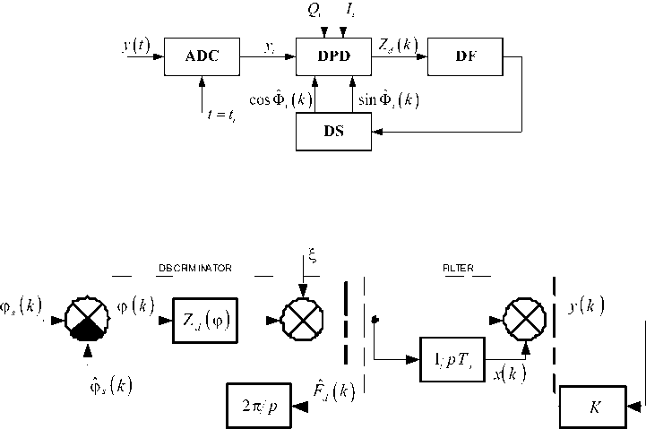
Fig. 2
Analysis of statistic simulation data of PLCS (Fig. 2) shows, that algorithm (3) is well-behaved if rated value Ymax = 40 dB , on the assumption of user’s top speed equals Vmax = 100 km/h (peak level of frequency Doppler shift Fd = 0,2Hz), signal-to-noise ratio threshold q = -40dBand capture dmax probability Pc ^ 1. Noise-immunity increase of PLCS ( ymax > 40dB) can be achieved by using a separate channel for an information signal. In this case the algorithm (3) can be simplified and written as Zd (k) = z2(k). Consequently, there are the following ways of frequency Doppler shift estimation:
F d ( k ) = '
F Л k ) =
K [ Z d ( k ) + , ( k -1 )+| Z d ( k - 1 ) ], M ■ -2,
it.
F T- ( M -1 ) , M * = 0, d I TpV ’
K I Z d ( k ) + x ( k -1 ) + T^Zd ( k -1 ) |, M * = 1,
T 2
(т Л (т т A ф, \T- ( m - 1)|-ф , |Tc ( m -1)-T^\
—^- p -----]—^- p--------p ^, M • = 0,
_ 2n - where M* = (M/2)-]M/2[, ]C[ - integer part separation operation, M = 1+]Tp(k-1)/Tc[ - MSK-signal cycle number.
Statistic simulation results of PLCS in case of adjacent channel interference and AWGN influence are presented in table 1. Results are the following: average and RMS values of phase and frequency errors of tracing in steady-state regime (SR). Number of statistical examination equals to 103 .
Table 1. PLCS statistic simulation results
|
Z d ( k ) |
sign( z 1( k )) z 2( k ) |
Z d ( k )= z 2 ( k ) |
Z d ( k )= z 2 ( k ) |
Z d ( k ) = z 2 ( k ) |
|
F ˆ d ( k ) |
F ˆ d ′ ( k ) |
F ˆ d ′ ( k ) |
F ˆ d ′′ ( k ) |
F ˆ d ′′′ ( k ) |
|
ϕ sr, rad |
0 |
0 |
0 |
0 |
|
σϕsr, rad |
0,09 |
0,09 |
0,45 |
0,08 |
|
F sr , Hz |
0 |
0 |
0 |
0 |
|
σ F sr , Hz |
0,035 |
0,035 |
0,039 |
0,028 |
|
γ max , dB |
40 |
75,6 |
54 |
80 |
Conclusion
The best for PLCS in case of adjacent channel interference influence is algorithm (6), which provides phase error of tracing RMS σϕsr ≈0, 08 rad with capture probability Pc → 1 , Fd max = 0,2 Hz , signal-to-noise ratio threshold q =-40 dB and γmax =80 dB .
Acknowledgements
The author would like to thank the following persons: prof. V. N. Bondarenko; prof. V. I. Kokorin; L. A. Deeva; associate prof. V. A. Vyahirev.
These investigations are realized with the help of grant № 08-08-00849-а of Russian Foundation for Basic Research (RFBR) and program of scientific and educational evolution program for Siberian federal university.
