Comparing simulated results of folded and unfolded log-periodic antenna used for observing the Sun

Author: Sha Li, Yihua Yan, Zhijun Chen, Wei Wang
Journal: Солнечно-земная физика @solnechno-zemnaya-fizika
Article in issue: 2 т.5, 2019.
Free access
There are two antenna arrays located in Mingantu Spectral Radio Heliograph (MUSER). MUSER-I and MUSER-II cover the frequency band ranging from 0.4 to 2 GHz and from 2 to 15 GHz respectively. A third antenna array covering 30-240 MHz will be established in the coming years. A log-periodic antenna is one of the choices for MUSER low frequency band; it radiates structures capable of maintaining consistent impedance characteristics over a wide bandwidth. Due to the ability of achieving high gain, it is widely used in many broadband applications. In this program, folded and unfolded log-periodic antennas are simulated for the Meridian project. In order to improve its return loss, this antenna is optimized with the width of each pole and the height of the substrate. This optimized process has been implemented in the simulated software HFSS.
Array, feed, log-periodic antenna
Short address: https://sciup.org/142220336
IDR: 142220336 | UDC: 621.396.075 | DOI: 10.12737/szf-52201907
Сравнение результатов моделирования сложенной и развернутой логопериодической антенны, используемой для наблюдений Солнца
В спектральном радиогелиографе Минганту (MUSER) есть две антенные решетки. MUSER-I и MUSER-II охватывают диапазон частот от 0.4 до 2 ГГц и от 2 до 15 ГГц соответственно. В ближайшие годы будет создана третья антенная решетка, охватывающая частотный диапазон 30-240 МГц. Логпериодическая антенна является одним из вариантов для низкочастотного диапазона MUSER, она излучает структуры, которые способны поддерживать последовательные импедансные характеристики в широкой полосе пропускания. Благодаря высокому коэффициенту усиления, она широко используется во многих широкополосных приложениях. В этой программе сложенные и развернутые логпериодические антенны моделируются для проекта “Meridian”. Для того чтобы уменьшить потери на отражение, эта антенна оптимизирована с учетом ширины каждого полюса и высоты опоры. Этот оптимизированный процесс был реализован в смоделированном программном обеспечении HFSS.
Text of the scientific article Comparing simulated results of folded and unfolded log-periodic antenna used for observing the Sun
MUSER [Li et al., 2016] is an aperture synthesis solar radioheliograph. It is located at ~400 km away from Beijing. Another new telescope with a 30–240 MHz frequency band is now being tested for observing the Sun in a lower frequency band. The main specifications of MUSER-I and MUSER-II [Li et al., 2015a] are shown in Table 1.
Now, MUSER-I and MUSER-II has a routine procedure to observe the Sun every day. In solar radio ob- servations, the Sun exhibits a variety of large dynamic phenomena in different frequencies [Lesovoi et al., 2014]. Meanwhile, it transmits constant energy to Earth. These phenomena reveal links between solar astronomy and other branches of physics. The gyro-synchrotron emission has been taken as an explanation for most broadband types of bursts, which are observed due to plasma emission processes. Hence, the study of meter wavelength solar radio bursts leads naturally to the theory of waves in plasma.
-
Table 1
The main specifications of MUSER
|
Parameter |
MUSER-I |
MUSER-II |
|
Frequency band |
0.4–2 GHz |
2–15 GHz |
|
Wavelength |
75–15 cm |
15–2 cm |
|
Number of antennas |
40 |
60 |
|
Channels |
64(25 MHz) |
520(25 MHz) |
|
Spectral resolution |
10.3″(2 GHz)– 51.6″(400 MHz) |
1.4″(15 GHz)– 10.3″(2 GHz) |
|
Flux sensitivity |
3·10–4 sfu/beam ( integration time is 1 s, bandwidth is 25 MHz ) |
|
|
Time resolution |
25 ms |
~200 ms |
|
Dynamic range |
more than 25 dB |
|
|
Circular polarization |
R, L |
|
|
Longest baseline |
3 km |
|
|
Field of view |
2–7 degree 0.2–6 degree |
|
-
Table 2
Specifications of MUSER-MDA
|
Frequency band |
30–240 MHz |
|
Wavelength |
10–1.25 m |
|
Antenna number |
100 |
|
Flux sensitivity |
3 sfu |
|
Spectral resolution |
1.7 ' (240 MHz) 14.0 ' (30 MHz) |
|
Time resolution |
100 ms |
|
Longest baseline |
3 km |
Considering solar flares at various heights in the atmosphere ranging below the chromosphere through the corona and into interplanetary space, it is not easy to identify manifestations in one wavelength because flares often include a wide range of phenomena. At each height range, observations in specific wavelength bands have provided different information. The magnetic field strength in the corona within active regions is rather uncertain because there are yet no reliable techniques for direct measurements. The best values to date come indirectly form radio observations. Over the whole electromagnetic spectrum of the Sun, the meter wavelength band [Chen, Chia, 2000] is unique, the photosphere and chromosphere and longer wavelength come mainly from interplanetary space, meter waves alone are generated inthe tenuous plasma known as the solar corona, and they reveal a spectacular range of undreamed-of phenomena.
Since we have already built decametric and centimetric telescopes, the next plan is to construct a telescope with a 30–240 MHz bandwidth, which is named MingantU SpEctral Radio Heliograph Metric to decametric Array (MUSER-MDA). It differs from the former ones and is designed as folded log-periodic antenna; all the antennas are also located in three spiral beams. The main specifications of MUSER-MDA are shown in Table 2.
UNFOLDED LOG-PERIODIC ANTENNAS
A series of printed log-periodic antennas [Lai et al., 2017] have been proposed, and most of them are evolved from the traditional LPDA; a cross feeding structure has been adopted which feeds on one side of a short dipole. Such a feeding method cannot be integrated. The log-periodic dipole antenna (LPDA) [Wang et al., 2011] is, however, widely used due to its simple structure, good performance and wide bandwidth. The basic concept is the gradually expanding periodic dipoles radiating most effectively when the array is nearly resonant so that antenna characteristics in a cycle change little, therefore LPDA belongs to the non-frequencydependent antenna and it is the representative of the popular wideband antennas.
LPDA is a classic non-repeat form of frequency varying antenna [Zhengguang et al., 2006] ; its impedance and radiation characteristics are repeated by the logarithm of the frequency. The transmission of electromagnetic energy is from the feed point along the antenna structure to push forward. The resonance occurs at the teeth of a quarter-wavelength and then the radiation occurs. The remaining part of energy moves forward and then is reflected back at the end of the antenna, where the energy is weak. When the frequency is changed,
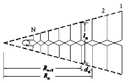
Figure1 . The schematic of the LPDA
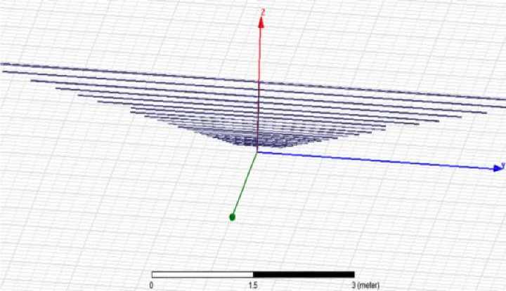
Figure 2. Model of log-periodic antenna
dB(GainTotal)
8.Ч199е*000 Ч.1131е+000 -1.937Че-001 -Ч.50О6е*000 -8.807Че*000 -1.311Че*001 -1.7Ч21е»001 -2.1728е»001 -2.6035е»001 -3.03Ч2е«001 -З.Ч6Ч8е+001 -3.8955е*001 -Ч.3262е*001 -Ч.7569е+001 -5.1876е»001 -5.6182е*001 -6.0Ч89е*001


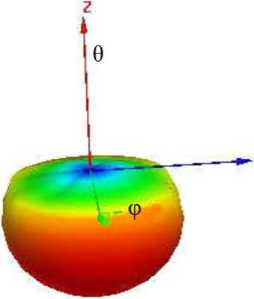
Figure 3. Radiation pattern at 30 MHz
the resonant point moves too. But the geometric form of the antenna is not be affected by the move of the resonant point. The feed way of LPDA is a cross power feeding. The feeder is a cross-connection between two adjacent poles, and the purpose is to ensure the poles in the radiation area can obtain appropriate phase relationship. So that the phase of long poles is before the short ones, thereby the result is the end fire pointing to the vertex direction. Figure 1 gives a schematic of the log-periodic antenna array.
The features of pattern, gain, and impedance depend on the scaling factor τ:
can be connected with a resistance equal to its characteristic impedance, as well as up to the back of the unit within λ max /8 distance. The characteristic impedance of the feeder can affect the input impedance of the antenna. Its relationship is expressed as
Z c
Z


lrd n n n т
;
n - 1 n - 1 n - 1
d n _ (1 -t ) r n ;
0_ tan( - 1) | ln | .
I r n )
The length of each pair of pole is half wavelength. The frequency band is 30~240 MHz, hence the longest length of a pair of dipole is 5 m. The traditional LPDA shown in Figure 2 is simulated, the size of this antenna is very large — it does not fit the requirement of the project. So, the folded LPDA is designed and simulated. Figure 3 gives a 3-dimension radiation pattern at 30 MHz. Figure 4 shows the radiation patterns at 240 MHz. The biggest gain value is about 11.7 dBi.
In these three equations, l represents the half wavelength of the pole; r is the distance between the vertex and each pole; d is the distance between two adjacent dipoles; θ is the angle. At the end of the feed lines, they
RESULTS OF FOLDED LPDA
According to the big size of traditional LPDA, this folded antenna model is also set up in the software HFSS [Li et al., 2015b] . The modeling process is illustrated

dB(GalnTotal)
1.170Se+001 7.1925e-000 2. 6804e-000
-1. 8317e+000 -6.3438e+000 -1.0856e+001
। -1.5368e+001 К -1.98806+001 1 -2.4392e+001 В -2.8904e*001 I -3.3417e+001 1 -3.7929e+001 1 -4.24416-001
-4.6953e-001 -5.14656-001 -5.59776-001 -6.04896-001
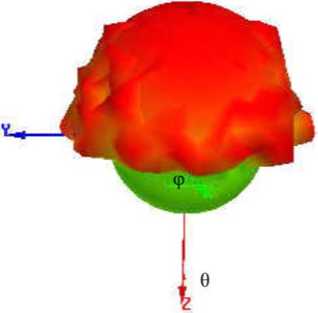
Figure 4. Radiation pattern at 240 MHz
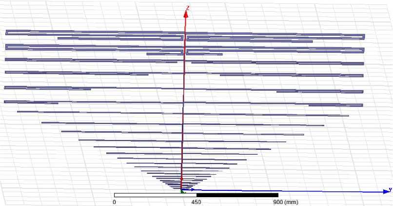
Figure 5. The folded LPDA as follows: major parameters are confirmed, some other parameters are optimized in an appropriate range in the software, and then the best parameter is chosen. When the distance between feeder lines is too small, the current amplitude is also inverted, so that in the far-field region the feeder lines affect each other.
The shape of the folded LPDA is much like the normal LPDA. The frequency band width is 30–240 MHz, the designed return loss is less than –10 dB; the gain is larger than 6 dBi. The folded LPDA is comprised of substrate, feed lines, and poles. A 3 mm-thick FR4 antenna substrate with a permittivity of 4.4 and a loss tangent of 0.02 is used; the length, width and the height of the substrate dimension are set as 2×1×0.003 m3. Finally, the main PCB of the dimension is the system plane.
Figure 5 shows the folded dipoles arranged in the simulated software. The maximum length of the dipole is 2 m and the height of LPDA is 1 m. The number of the dipoles is 27, the shortest and longest poles are designed as l 0 and l 26, the distance between the pole and the original point is denoted by d , the width of each pole is w . The values of each pole are given in Table 3.
At the beginning of the simulation, the widths of the dipoles use the value listed in the Table, and then the thickness of the optimized value is from 2 to 20 mm.
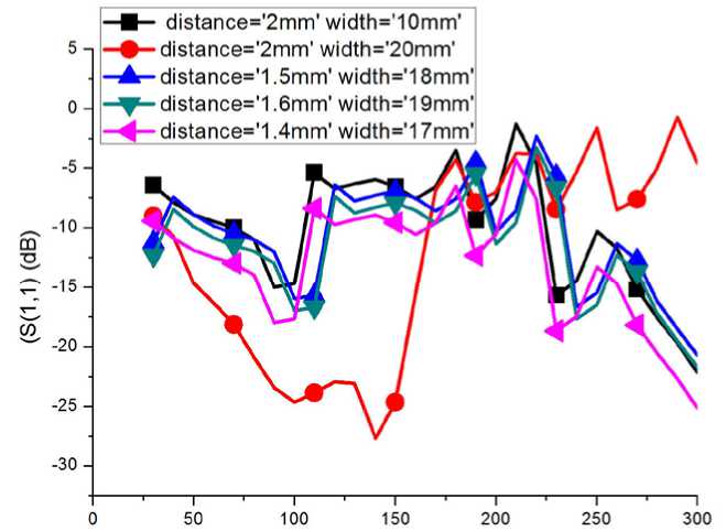
The simulated return loss is shown in Figure 6; different parameters show different simulated results. Figure 7 and 8 show the radiation patterns at frequencies of 30 and 240 MHz. According to this calculation, we could pick up optimized parameters for this log-periodic antenna. The next step is to find a more optimized parameter; the aim of the return loss is less than –10 dB. Up to now, we have calculated original optimized parameters. Much work will be done later.
CONCLUSION
In this paper, we present a novel type of folded LPDA, which is operated over the width from 30 to 240 MHz, the gain fluctuation could be improved by optimizing the width and length of the dipoles. Compared with the conventional unfolded LPDA, the folded LPDA has compact size and similar radiation characteristics. Hence, the next work will be done to make physical antenna model and measurement.
Freq (MHz)
Figure 6. The return loss of the antenna at three different parameters
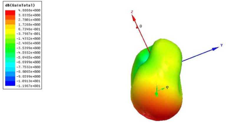
Figure 7. The radiation pattern at f =30 MHz
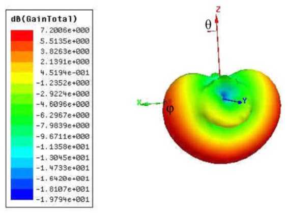
Figure 8. The radiation pattern at f =240 MHz
Table 3
Parameters of the proposed antenna
|
Dipole |
Length, mm |
Distance, mm |
Width, mm |
|
l 0 |
40 |
3.6 |
1.0 |
|
l 1 |
46.8 |
7.7 |
1.1 |
|
l 2 |
55 |
12.5 |
1.2 |
|
l 3 |
64 |
18 |
1.3 |
|
l 4 |
75 |
24.3 |
1.4 |
|
l 5 |
87.6 |
31.5 |
1.5 |
|
l 6 |
103 |
39.8 |
1.6 |
|
l 7 |
120 |
49.4 |
1.7 |
|
l 8 |
140 |
60.4 |
1.9 |
|
l 9 |
164 |
73.1 |
2 |
|
l 10 |
192 |
87.7 |
2.2 |
|
l 11 |
226 |
104 |
2.3 |
|
l 12 |
264 |
124 |
2.5 |
|
l 13 |
308 |
146 |
2.7 |
|
l 14 |
360 |
171 |
2.9 |
|
l 15 |
422 |
201 |
3.2 |
|
l 16 |
494 |
234 |
3.4 |
|
l 17 |
578 |
273 |
3.6 |
|
l 18 |
676 |
318 |
4 |
|
l 19 |
788 |
369 |
4.3 |
|
l 20 |
924 |
428 |
4.7 |
|
l 21 |
1300 |
495 |
5 |
|
l 22 |
1480 |
573 |
5 |
|
l 23 |
1800 |
663 |
5 |
|
l 24 |
1960 |
733 |
5 |
|
l 25 |
2200 |
813 |
5 |
|
l 26 |
2700 |
893 |
5 |
This work is supported by the National Natural Science Foundations of China (Grant Nos. 61572461, 11790301, 11790305, 11573043, 11433006). It is also supported by the Specialized Research Fund for State Key Laboratories.
References Comparing simulated results of folded and unfolded log-periodic antenna used for observing the Sun
- Chen Z.N, Chia Y.W.M. Broadband monopole antenna with parasitic planar element. Microwave and Optical Technology Lett. 2000, vol. 27, iss. 3, pp. 209-210. DOI: 10.1002/1098-2760(20001105)27:3%3C209::AID-MOP19% 3E3.0.CO;2-5.
- Lai J.Y., Hsu C.W., Li K.W., et al. A wideband CPW-fed monopole antenna with linear and circular polarizations. Proc. IEEE International Symposium on Antennas and Propagation & USNC/URSI National Radio Science Meeting. 2017, pp. 327-328.
- Lesovoi S.V., Altyntsev A.T., Ivanov E.F., Gubin A.V. A 96-antenna radioheliograph. Res. in Astron. and Astrophys. 2014, vol. 14, iss. 7, pp. 864-868 DOI: 10.1088/1674-4527/14/7/008
- Li S., Yan Y., Chen Z., Wang W., Zhang F. Design of dual circularly polarized 2-15 GHz feed and the polarization degree measurement for CSRH-II antenna system. Publ. of the Astron. Soc. of Australia (PASA). 2015a, vol. 32, e013, pp. 1-7 DOI: 10.1017/pasa.2015.14
- Li S., Yan Y.-H., Chen Z.-J., Wang W., Liu D.-H. Antenna system characteristics and solar radio burst observations. Res. in Astron. and Astrophys. 2015b, vol. 15, no. 11, pp. 1917-1930 DOI: 10.1088/1674-4527/15/11/013
- Li S., Yihua Y., Zhijun C., Wang W. A new impedance matching method for an ultra-wide band and dual circularly polarised feed. Publ. of the Astron. Soc. of Australia (PASA). 2016, vol. 33, e061, pp. 2-8 DOI: 10.1017/pasa.2016.51
- Wang J., An K., Liu Y. Analysis of electrical characteristics of LPDA and HFSS simulation design. Proc. 4th IEEE International Symposium on Microwave, Antenna, Propagation and EMC Technologies for Wireless Communications. 2011 DOI: 10.1109/MAPE.2011.6156145
- Zhengguang Y., Donglin S., Shanwei L. A size-reduced log periodic dipole antenna. J. of Electronics. 2006, vol. 23, no. 6, pp. 913-914 DOI: 10.1007/s11767-005-0048-3
