Comparison based Analysis of Different FFT Architectures

Author: Priyanka S. Pariyal, Dhara M. Koyani, Daizy M. Gandhi, Sunil F. Yadav, Dharam J. Shah, Ankit Adesara
Journal: International Journal of Image, Graphics and Signal Processing(IJIGSP) @ijigsp
Article in issue: 6 vol.8, 2016.
Free access
A time-domain sequence is converted into an equivalent frequency-domain sequence using discrete Fourier transform. The reverse operation converts a frequency-domain sequence into an equivalent time-domain sequence using inverse discrete Fourier transform. Based on the discrete Fourier transform. Fast Fourier transform (FFT) is an effective algorithm with few computations. FFT is used in everything from broadband to 3G and Digital TV to radio LAN's. To improve its architecture different efficient algorithms are developed. This paper gives an overview of the work done by a different FFT processor previously. The comparison of different architecture is also discussed.
FFT(Fast Fourier Transform), FFT algorithms, area efficient FFT, Speed efficient FFT
Short address: https://sciup.org/15013986
IDR: 15013986
Text of the scientific article Comparison based Analysis of Different FFT Architectures
Published Online June 2016 in MECS DOI: 10.5815/ijigsp.2016.06.05
Discrete Fourier Transform (DFT) converts frequency domain signal to Frequency domain signal. Fast Fourier is efficient way to calculate Discrete Fourier Transform (DFT). There are different FFT algorithms to calculate Discrete Fourier Transform. Fast Fourier transform (FFT) is used in digital signal processing algorithms and it plays a significant role in many applications of signal processing, also it is used in radar, medical electronics. Some specific applications of Fast Fourier Transform (FFT) includes spectrum analysis for detecting and analysing signals, for coding audio and speech signals in frequency domain(mp3), in orthogonal frequency division multiplexing (OFDM).
The DFT Algorithm is defined as
( )n к
X(Ю=^х(п)е ’(1)
W„ = e"7'^)
X (k)=^x(n)WSk(3)
These equations show that for computation of N-point DFT, N²complex multiplications and N (N-1) complex additions are required. The number of computations will go to lakhs if value of N is larger. For this reason, the number of multiplications and additions should be reduced. So the FFT algorithm is an efficient algorithm to compute the DFT. Some of the FFT algorithms are as follows:
-
1) Cooley-Tukey algorithm
-
2) Prime factor algorithm
-
3) Winograd FFT algorithm
-
4) Rader’s FFT algorithm
-
5) Bluestein’s FFT algorithm
Section II gives different FFT algorithms, these include area efficient, speed efficient algorithm and power efficient algorithm. Section III gives comparisons of FFT algorithm based on Cost, Complexity, Operating frequency, Operation, size of input, adder and multiplier.
-
II. Algorithms
There are different FFT algorithms to compute DFT which are as below.
-
A. Cooley Tukey Algorithm.
The Cooley-tukey algorithm is the most commonly used FFT. This is a divide and conquer algorithm that recursively breaks down a DFT of any composite size N = N 1 N 2 into many smaller DFTs of sizes N 1 and N 2 .The Cooley–Tukey algorithm is best use to divide the transform into two pieces of size N/2 at each step, and so it is limited to power-of-two sizes, but any factorization can be used in general [1]. These are called the mixed-radix cases and radix 2.
Two different algorithm Procedures are introduced to compute a Cooley-Tukey FFT:
-
a) Decimation-in-frequency (DIF)
-
b) Decimation-in-time (DIT).
The FFT gives same result as the DFT but with fewer computations. This reduction becomes more and more important with higher-order FFT. Identical results are obtained with an FFT using either the decimation-infrequency (DIF) or the decimation-in-time (DIT) process. DIT (Decimation in Time domain) is process that decomposes the input sequence into smaller sequences i.e. Input sequences are decimated or in bit reversed order and output is in proper order [2] as shown in Fig. 1. DIF (Decimation in frequency domain) is process that decomposes the output sequence into smaller sequences i.e. Output sequences are decimated or in bit reversed order and input is in proper order [2] as shown in Fig. 2. Hence a reordering block is required in input section for DIT, while in DIF reordering block is required in output section.
Decimation-in-time (DIT) and Decimation-infrequency consists of Butterfly unit, which is given in fig.3 .Butterfly unit is the heart of DIT and DIF algorithm where,
Y 1 = X1 + X2 (4)
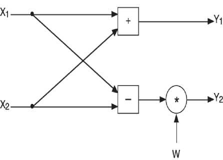
Fig.3. Butterfly Unit
Y 2 = X1 + (X2 * W) (5)
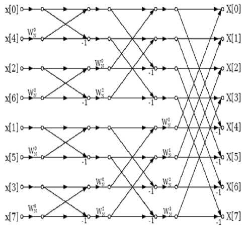
Fig.1. Decimation in Time Domain
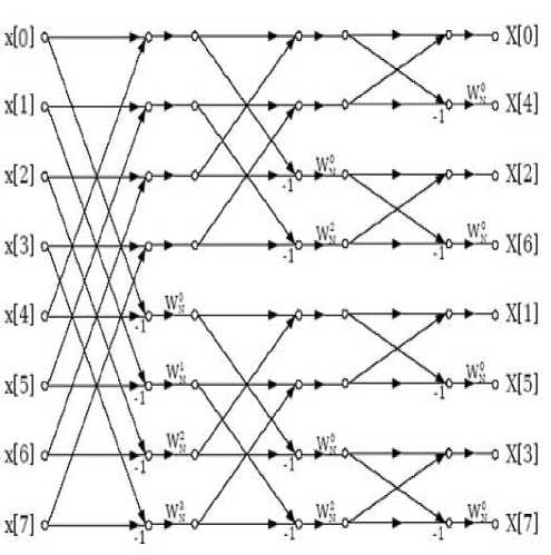
Fig.2. Decimation in Frequency Domain
-
B. Prime Factor Algorithm
The prime-factor algorithm (PFA)/Good–Thomas algorithm (1958/1963), is a fast Fourier transform (FFT) algorithm that expresses the discrete Fourier transform (DFT) of a size N = N 1 N 2 as a two-dimensional N 1 ×N 2 DFT, but the condition is N 1 and N 2 are relatively prime. PFA or other FFT algorithm can be recursively used to evaluate these smaller transforms of size N 1 and N 2 [3].
-
C. Radar And Brenner’s Algorithm
The Rader-Brenner algorithm (1976) is a Cooley– Tukey like factorization with purely imaginary twiddle factors, reducing multiplications but increasing additions and reducing numerical stability; it was replaced by the split-radix variant of Cooley–Tukey (which achieves the same multiplication count but with less additions and without reducing accuracy) afterwards.
-
D. Bluestein’s Algorithm.
Bluestein's algorithm expresses the Chirp Z-Transform (CZT) as a convolution and implements it efficiently using FFT/IFFT.DFT is a special case of CZT, so this allows efficient computation of the discrete Fourier transform of arbitrary size, including the prime size. It was developed in 1968 by Leo Bluestein .Bluestein algorithm can be used to calculate more transforms than the DFT, based on z transform.
-
E. Winograd Algorithm.
Winograd algorithm is difficult to program and are rarely used. ZN-1 is factorized into polynomials having 1,0 or -1 coefficients. So, few multiplications are required. Winograd also showed that only through irrational multiplications the DFT can be computed, but this increases the cost of hardware [15].
-
F. Brunn’s Algorithm .
This algorithm was proposed by G.Brunn in 1978 for power of two. A recursive polynomial factorization method is used in Brunn’s algorithm [15].
-
G. Area Efficient FFT:
A FFT block can become area efficient by using following ways:
-
a) By reusing the butterfly units[6]
-
b) By converting Complex multiplier into additions and subtractions[8]
-
a) By reusing the butterfly units [6]
The total number of butterfly units used shows the area of a FFT processor, in each butterfly unit multiplier and adder/subtractor blocks are present. The area of these two mathematical blocks becomes larger as the bit resolution of samples becomes higher. Each stage contains N/2 numbers of butterfly units according to traditional FFT algorithm. Therefore, for traditional FFT processor the total number of butterfly unit is given by
BU Traditional_FFT = (N/2)log 2 N (6)
While N/2 numbers of butterfly units are reused for log 2 N times in area efficient algorithm. Therefore, number of butterfly units required by the area efficient FFT architecture is given by
BU area_efficient_FFT = N/2 (7)
So, the area efficient architecture of FFT processor reduces the number of butterfly units by a factor of (a), which is given by
N /2 a = ——--- N /2 log a = log 2 N 1 a = log w 2 (8)
Table 1. Comparison of traditional FFT and FFT reusing Butterfly Unit
|
Traditional FFT |
FFT Reusing The Butterfly Unit |
|
|
Butterfly Unit |
N/2 Log 2 N |
N/2 |
|
Multiplier |
N/2 Log 2 N |
N/2 |
|
Adder/Subtractor |
N Log 2 N |
N |
For N=8 , Traditional FFT will require 12 butterfly unit , 12 Multiplier and 24 Adder/substractor ,while When Butterfly unit is reused FFT will require only 4 Butterffly unit, 4 Multiplier and 8 adder/substractor block.
-
b) By substituting complex multiplier with additions and subtractions [8].
The speed and output of FFT is severely affected by complex multiplications. Four real multipliers and two real adders are required for complex multiplications as shown in equations below,
(R + jI ) = (B r + j В i)( Wr + jW i)
= Br * Wr + jBi * Wr + jBr * W i — В i * Wi =[(Br * Wr) — (Bi * Wi)] + j[(Bi * Wr) + (Br * Wi)]
So instead of using four real multiplication and two real adder it is substituted by three real multiplications and five add/substract as shown in Fig. 3, because hardware area of real adder/substracter is comparatively less then hardware area of complex multiplier.
(R + jQ = (B r + j В i)( Wr + j Wi)
This Complex multiplication can be as follows:
R = [Br(Wr + W i) — (Br + B OW i] (10)
I = [Br (Wr + W i) — (B r — B i) Wr] (11)
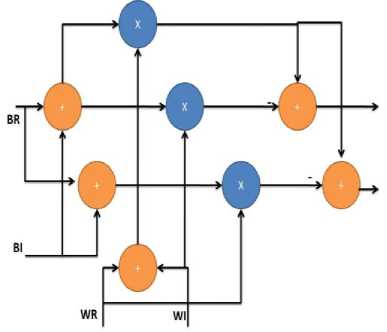
Fig.4. Complex Multiplier
Table 2. Comparison Between Traditional FFT And FFT Using Less Multiplier
|
Traditional FFT |
FFT using less multipliers |
|
|
Butterfly Unit |
N/2 log 2 N |
N/2 log 2 N |
|
Complex Multiplier |
N/2 log 2 N |
N/2 log 2 N |
|
No of multiplications in one Complex Multiplier |
4 |
3 |
-
H. Speed Efficient FFT:
The speed of FFT block can be increased by following ways:
-
a) Implementations of serial FFT and IFFT architecture in one block without reordering block [4]
.
-
b) By using parallel and pipelining method to implement FFT [5].
-
a) Implementation of serial FFT and IFFT architecture in one block without using reordering block.
In most serial Fast Fourier Transform (FFT), output of the serial FFT block is in bit-reversed order, so to reorder the output a reordering block is needed. But, in some FFT applications ordered output of FFT is not required, for example: Spectral Subtraction method (Spectral Subtraction Method is effective method to reduce noise without affecting the speech signal quality). So, some clock cycles latency can be saved by not implementing the reordering block and increase speed of the block. Here, FFT and IFFT are performed in same block [4].
By not implementing reordering block ,we save N clock cycles for N point FFT/IFFT , but we require delay block so that one input data operates with correct other input data.
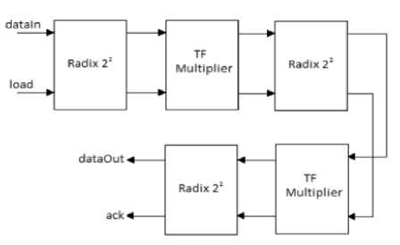
Fig.5. Block Diagram FFT without Reordering Block
In fig. 4 ,Radix 22 blocks contains radix 2A , shown in fig. 6 and radix 2B block , shown in fig. 7 (radix 2X in general).A delay block is there with every radix 2X block to make sure that one input data operates with the correct other input. Delay blocks are implemented that is able to give different clock delays according to order of its input, when no reordering block is implemented.
For N -points FFT with ordered input, the first delay block has to make delay of N /2 clock cycles, and then the second delay block has to make delay of N /4 clock cycles, and it will continue till the last block that gives delay of 1 clock cycle. For N -points IFFT operation with unordered input, delay of 1 clock cycle is given by the first delay block, then the next delay block gives delay of 2 clock cycles, and it will continue till the last block that gives delay of N /2 clock cycles.
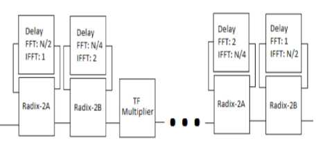
Fig.6. Block diagram of Radix 22
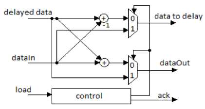
Fig.7. Radix 2A Block
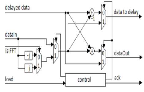
Fig.8. Radix 2B Block
Table 3 Comparison Between Traditional FFT and FFT Without Reordering Block
|
Block |
Traditional FFT |
FFT/IFFT block without reordering Block |
|
Length |
16 |
16 |
|
No of Cycles |
192 |
73 |
-
b) By using parallel and pipelining method to implement FFT.
The FFT algorithm when uses parallel and pipelining method the Latency becomes (N/ 2) Log 2 N +11 [5].
-
I. Power Efficient FFT:
Low power FFT can be formed using split radix Fast Fourier Transform (SRFFT). Split Radix Fast Fourier Transform (SRFFT) uses less number of multiplications even when FFT size increases, that results to low power consumption compared to other Fast Fourier transforms(FFT) for input length N equals to 2m(m is any natural number).Generally, in split radix Fast Fourier Transform (SRFFT) radix-2 is mapped to even index terms and radix-4 is mapped to odd index terms, so it results to ‘L’ shaped butterfly. Now to reduce the power consumption butterfly unit is modified, it uses clock gating approach (reduction in dynamic power dissipation) to block unnecessary switching in multiplier. By using this approach a 32 point FFT could achieve a power saving of 11.2% with slightly increase in static power and critical path delay.
-
III. Comparison of the FFT architecture
All the FFT algorithms have its own advantage and disadvantage which are given in Table 4 and Table 5.In cooley tukey algorithm DIT or DIF method is used to solve FFT which divides N point into M and N/M point DFT’s, also cost and complexity is comparatively less but operating frequency is worst. Prime factor algorithm is very much useful , also operating frequency is good and is cost effective but it has a constrain that Prime factor algorithm is useful only when N1 and N2 are relatively prime. Winograd algorithm uses convolution method to solve FFT, operating frequency is good but cost and complexity is more of winograd algorithm. Winograd is extremely efficient for small number of N points, but number of adds become more for large N so winograd algorithm becomes difficult to use.Rader and brenner’s algorithm is efficient for prime length N, split radix method is used to solve FFT, also cost is high , complexity is more and operating frequency is worst of Rader and brenner’s algorithm. Brunn’s algorithm has good operating frequency, it uses polynomial factorization method to solve FFT , also cost is moderate and complexity is less.
Table 4. Comparisons of FFT Algorithm Based on Cost, Complexity , Operating Frequency and Operation
|
Algorithms |
Method’s used to solve FFT |
Cost |
Complexity |
Operating Frequency |
Operation |
|
Cooley-Tukey |
DIT & DIF FFT algorithm |
Low |
Less |
Worst |
Divide N-pt into M,N/M pt DFT’s |
|
Winograd |
Convolution method |
High |
More |
Good |
Factorize Z^N-1 into various polynomials |
|
Rader-brenner |
Split-radix FFT algorithm |
High |
More |
Worst |
Computes N-pt DFT with N=2^t |
|
Brunn’s |
using polynomial factorizing |
Moderate |
Less |
Good |
Computes DFT of real co-efficient |
|
Prime factor/ Good Thomas |
Two dimensional DFT algorithm |
Low |
Moderate |
Better |
Re-express the DFT but only for the case where N1 and N2 are relatively prime. |
Table 5. Comparisons of FFT Algorithm Based on size of input, Multiplier and Adder
|
Algorithms |
Comparison with size of input and multiplier and adder in algorithm |
|
Cooley-Tukey |
N/2·log 2 N complex multiplier and N·log 2 N Complex adder. We can give N size of input to this algorithm. Reducing the number of multiplier but increase the number of adder |
|
Winograd |
Using a convolution scheme |
|
Rader-brenner |
We can give N size of input to this algorithm. Reducing the number of multiplier same as cooley tukey but decrease the number of adder too. |
|
Brunn’s |
Using by polynomial factorizing |
|
Prime factor |
Using two dimensional DFT methods so only for the small size input. Based on the two dimensional DFT. |
|
Bluestein’s algorithm |
By using convolution FFT will be founded and inputs are only in arbitrary and prime size. It calculate DFT on base on the Z-transform |
-
IV. Conclusion.
We studied different FFT algorithm like Cooley Tukey algorithm, Prime Factor/ Good Thomas algorithm, Winograd algorithm, Brunn’s algorithm, Rader and brenner’s algorithm and Bluestein algorithms. Among these algorithms complexity of Cooley tukey algorithm is less comparitively and its cost is also less, but operating frequency of Winograd algorithm and brunn’s algorithm is good compare to other algorithm. Winograd algorithm is advantageous for small value of N, as N becomes large its complexity increases. Prime factor/Good Thomas algorithm has better operating frequency compared to cooley tukey algorithm but Prime factor /Good Thomas algorithm can be used only for relatively prime N1 and N2. Comparisons of these different algorithms are given in terms of cost, complexity, operating frequency, size of input, size of adder and multiplier. Besides these, there are ways to make FFT algorithm area efficient like by reusing butterfly unit and by replacing complex multiplier by adder and substractor unit .For speed efficient FFT algorithms two methods are given ,first by using parallel and pipelining method and second by eliminating reordering block. For power efficient Fast Fourier transform split radix fast Fourier transform (SRFFT) is used in which clock gating approach is used
Acknowledgment
We would like to express our deep sense of respect and gratitude towards Prof. Dharam Shah and Prof. Ankit Adesara for their constant encouragement and invaluable advice..
References Comparison based Analysis of Different FFT Architectures
- Daniel N. Rockmore_" The FFT - an algorithm the whole family can use", Departments of Mathematics and Computer Science ,Dartmouth College , October 11, 1999
- DSP Applications Using C and the TMS320C6x DSK. RulphChassaing © 2002 John Wiley & Sons, Inc.
- CliveTemperton ," A GENERALIZED PRIME FACTOR FFT ALGORITHM FORANY N = 2'3'5" *" , SIAM J. ScI. STAT. COMPUT. ,Vol. 13, No. 3, pp. 676-686, May 1992(C) 1992 Society for Industrial and Applied Mathematics003.
- Muhammad FirmansyahKasim, Trio Adiono, Muhammad Fahreza, Muhammad FadhliZakiy, "FPGA Implementation of Fast Serial 64-Points FFT/IFFT Block without Reordering Block", Bandung, Indonesia
- N. Mahdavi, R. Teymourzadeh, IEEE Student Member, Masuri Bin Othman , "VLSI Implementation of High Speed and High Resolution FFT Algorithm Based on Radix 2 for DSP Application",The 5th Student Conference on Research and Development –SCOReD 200711-12 December 2007, Malaysia.
- Atin Mukherjee, AmitabhaSinha and DebeshChoudhury,"A Novel Architecture of Area Efficient FFT Algorithm for FPGA Implementation" , Neotia Institute of Technology, Management and Science.
- SnehaN.kherde,MeghanaHasamnis ,"Efficient Design and Implementation of FFT",International journal of Engineering Science and Technonlogy (IJEST), ISSN; Special Issue Feb 2011.
- Rajesh Mehra , Pooja Kataria ,National Institute of Technical Teachers, Training and Research, Chandigarh 160019, India "FPGA Based Area Efficient 64-Point FFT Using MAC Algorithm"
- S. W. Yu and E. E. Swartzlander, "A pipelined architecture for the multidimensional DFT," IEEE Trans. Signal Process., vol. 49 no. 9, pp.2096–2102, Sep. 2001.
- J. D. Bruguera and T. Lang, "Implementation of the FFT butterfly with redundant arithmetic," IEEE Trans. Circuits Syst. II, vol. 43, pp. 717–723, May 1996.
- Digital Signal Processing by John G. Proakis and Dimitris G.Monolakis
- Digital System Design using VHDL by Charles H.Roth ,Jr. Lizy kurian John
- International Journal of Emerging Trends in Signal Processing Volume 1 ,Issue 1, November 2012 "Comparative Study Of Various FFT Algorithm Implementation On FPGA" ,By Aniket Shukla and Mayuresh Deshmukh ,Mumbai University, B.E. Electronics ,Terna Engineering College, Nerul Navi Mumbai, India
- "FPGA Implementation of Low-Power Split-Radix FFT Processors", Zhuo Qian, Nasibeh Nasiri, Oren Segal, Martin Margala, University of Massachusetts Lowell, Lowell, MA,USA
