Comparison of Wireless MIMO System Under Alamouti's Scheme and Maximum Ratio Combining Technique

Author: Apoorva Pandey, Rafik Ahmad, Devesh Pratap Singh
Journal: International Journal of Image, Graphics and Signal Processing(IJIGSP) @ijigsp
Article in issue: 2 vol.5, 2013.
Free access
In wireless communication fading of channels is the serious cause of the received degraded signals. The effect of fading can be minimized by using various time and space domain techniques. However, space domain techniques are preferred over the others due to its advantages. In this paper, comparison of the wireless MIMO system under Almouti's and maximum ratio combining schemes is presented. Basic idea in these schemes is to transmit and receive more than one copy of the original signals. Using two transmitter antennas and one receiver antenna, the scheme provides the nearly same diversity order as the maximal-ratio receiver combining (MRRC) with one transmitter antenna, and two receiver antennas. Results for one transmitter and four receivers under MRRC is also presented and compared. Finally, results are presented while varying the average transmitted power.
Diversity, Maximal Ratio Combining, Rayleigh fading, Alamouti's Scheme and BER
Short address: https://sciup.org/15012560
IDR: 15012560
Text of the scientific article Comparison of Wireless MIMO System Under Alamouti's Scheme and Maximum Ratio Combining Technique
The next-generation wireless systems are required to have higher voice quality as compared to the present cellular mobile radio standards and provide high bit rate data services (up to 2 Mbits/s). At the same time, the remote units are supposed to be small lightweight pocket communicators. Furthermore, they are to operate reliably in different types of environments: macro, micro, pico- cellular, urban, suburban, and rural; indoor and outdoor, as well. In other words, the next generation systems are supposed to possess better quality and coverage, be more power and bandwidth efficient, and be deployed in diverse environments.
The fundamental phenomenon which makes reliable wireless transmission difficult is the time-varying multipath fading [1]. Increasing the quality or reducing the effective error rate in a multipath fading channel is extremely difficult. In additive white Gaussian noise (AWGN), using typical modulation and coding schemes, reducing the effective bit error rate (BER) from 10-2 to 10-3 may require only 1- or 2-dB higher signal to- noise ratio (SNR). Achieving the same in a multipath fading environment, however, may require up to 10 dB improvement in SNR. The improvements in SNR may not be achieved by a higher transmit power or additional bandwidth, as it is contrary to the requirements of the next generation systems.
Theoretically, the most effective technique to mitigate multipath fading in a wireless channel is that of the transmitter power control. If the channel conditions as experienced by the receiver on one side of the link are known by the transmitter transmitting on the other side, the transmitter can pre distort the signal in order to overcome the effect of the channel at the receiver. There are two fundamental problems with this approach. The major problem is the required transmitter dynamic range. For the transmitter to overcome a certain level of fading, it must increase its power by that same level, which in most cases is not practical because of the radiation power limitations and the size and cost of the amplifiers. The second problem is that the transmitter does not have any knowledge of the channel experienced by the receiver except in the systems where the uplink (remote to base) and the downlink (base to remote) transmissions are carried over the same frequency. Hence, the channel information has to be fed back from the receiver to the transmitter, which subsequently leads to the throughput degradation and considerable added complexity to both the transmitter and the receiver. Moreover, in some applications there may not be a link to feed back the channel information. Other effective techniques are time and frequency diversity. Time interleaving, together with error correction coding, can provide diversity improvements. In most scattering environments, antenna diversity is a practical, effective and, hence, a widely applied technique for reducing the effect of multipath fading [1]. The classical approach is to use multiple antennas at the receiver and perform combining or selection and switching in order to improve the quality of the received signal. The major problem in using the receive diversity approach is the cost, size, and power of the remote units. The use of multiple antennas and radio frequency (RF) chains (or selection and switching circuits) makes the remote units larger and more expensive. As a result, diversity techniques have almost exclusively been applied to base stations to improve their reception quality. A base station often serves hundreds to thousands of remote units. It is therefore, more economical to add equipment to base stations rather than the remote units. For this reason, transmit diversity schemes are very attractive. For instance, one antenna and one transmit chain may be added to a base station to improve the reception quality of all the remote units in that base station’s coverage area (in fact, many cellular base stations already have two receive antennas for receiver diversity. The same antennas may be used for transmit diversity). The alternative is to add more antennas and receivers to all the remote units. The first solution is definitely more economical.
Recently, some interesting approaches for transmit diversity have been suggested. A delay diversity scheme was proposed by Wittneben [2] [3] for base station simulating and later, independently, a similar scheme was suggested by Winters [4] for a single base station in which copies of the same symbol are transmitted through multiple antennas at different periods of time; hence creating an artificial multipath distortion. A maximum likelihood sequence estimator (MLSE) or a minimum mean squared error (MMSE) equalizer is then used to resolve multipath distortion and obtain diversity gain. The technique discussed in this paper is a simple transmit diversity scheme which improves the signal quality at the receiver on one side of the link by simple processing across two transmitter antennas on the opposite side. The obtained diversity order is equal to applying maximal-ratio receiver combining (MRRC) with two antennas at the receiver. The scheme may easily be generalized to two transmitter antennas and receiver antennas in order to provide a diversity order of 2 M . This is done without any feedback from the receiver to the transmitter and only with small computational complexity. The scheme requires no bandwidth expansion, as redundancy is applied in space across multiple antennas, not in time or frequency. The new transmitter diversity scheme can improve the error performance, data rate, or capacity of wireless communications systems. The decreased sensitivity to fading may allow the use of higher level modulation schemes to increase the effective data rate, or smaller reuse factors in a multicell environment to increase system capacity. The scheme may also be used to increase the range or the coverage area of wireless systems.
The paper is organized as follows. In the Sect. 2, overview of the MIMO system model is presented. Description of the diversity is explained in Sect. 3. In Sect. 4, overview of Maximum Ratio Combining is discussed. Alamouti’s Transmit Diversity Scheme is discussed in Sect. 5. Simulation Results are presented in Section 6, and finally Sect. 7, discusses the major conclusions of the paper.
-
II. MIMO SYSTEM MODEL
When a transmitter and a receiver, with an appropriate channel coding/decoding scheme, are equipped with multiple antennas, the presence of multipath fading can improve by achievable transmission rates [5] [6]. For such MIMO channels, several optimum space-time codes have been designed. Now, let us consider a single point-to-point MIMO system with arrays of n transmit and n receive antennas. In this case, focus on a
R complex base band linear system model described in discrete time. The general modeling of a channel as an abstract MIMO channel allows for a unified treatment using a compact convenient vector-matrix notation.
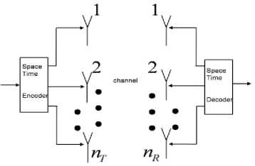
Fig. 1: MIMO system model
The system block diagram is shown in Fig. 1. The transmitted signals in each symbol period are represented by a nT x 1 Column matrix x , where the j -th component of x , refers to the transmitted signal from antenna j . A Gaussian channel has considered, for which, according to information theory, the optimum distributed of transmitted signal is also Gaussian. Thus, the elements of x are considered to be zero mean independent and identically distributed (i.i.d.) Gaussian variables. In [7], the covariance matrix of the transmitted signal is given by
Rxx = E (XXй) (1)
Where E{.}denoted the expectation and the operator AH denoted the Hermitian of matrix A , which mean the transpose and components- wise complex conjugate of A . According [5], the total transmitted power is constrained to P regardless of the number of transmit antennas. It can be represented as
P = tr (Rxx)
Where tr (A) denoted the trace of matrix A , obtained as the sum of the diagonal elements of A . By using the linear model, the received vector can be represented as are considered to be zero mean independent and identically distributed (i.i.d.) Gaussian variables. In [1] the covariance matrix of the transmitted signal is given by
r = Hx + n (3)
Where H is the channel matrix . Now ,the received signal covariance matrix, defined as E{rrH}, by using equation3, is given by
R rr = HR xx H H (4)
While the total received signal power can be expressed as t r (R rr ) .
-
III. DIVERSITY TECHNIQUES
Diversity techniques can be used to improve system performance in fading channels without the requirement of extra power or bandwidth. Instead of transmitting and receiving the desired signal through one channel, N copies of the desired signal through M different channels. The idea is that while some copies may undergo deep fades, others may not. So, enough energy can be obtained at the receiver to make the correct decision on the transmitted symbol.
-
A. Frequency Diversity
One approach to achieve diversity is to modulate the information signal through M different carriers. Each carrier should be separated from the others by at least the coherence bandwidth. So that copies of the signal undergo independent fading. At the receiver, the N independently faded copies are “optimally” combined to give a true decision. Frequency diversity can be used to reduce frequency selective fading.
-
B. Time Diversity
One more approach to achieve diversity is to transmit the desired signal in M different periods of time, i.e., each symbol is transmitted M times. The intervals between transmissions of the same symbol should be at least the coherence time so that different copies of the same symbol undergo independent fading. Optimal combining can also be obtained with the maximum ratio combiner.
-
C. Space Diversity
Another approach to achieve diversity is to use M antennas to receive M copies of the transmitted signal. The antennae should be spaced far enough apart so that different received copies of the signal undergo independent fading. In this type of diversity, no additional work is required on the transmission end, and no additional bandwidth or transmission time is required.
-
D. Receive diversity
Receive diversity is achieved using multiple antennas on the receiving end of the communication link. The method of using multiple antennas on the receiving end has been in use for over a number of years to improve the bit error rate (BER) performance. The basic idea is to have multiple signals with different degree of fading or different channel transfer function ‘ h ’. The signals are then appropriately combined with the help of diversity combining techniques. The basic configuration for receive diversity is depicted in Fig. 2.
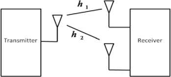
Fig. 2: Receive Diversity with two antennas
-
E. Transmit Diversity
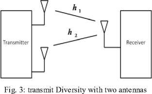
Transmit diversity is achieved using multiple antennas on the transmitting end of the communication link. The transmit diversity is far more advantageous as compared to the receive diversity. This is due to the fact that in general the number of receivers is greater than the number of transmitters. The transmit diversity is a modern phenomenon. The basic configuration for transmit diversity is shown in Fig. 3.
-
IV. MAXIMUM RATIO COMBINING
There are various techniques used to combine the signals from multiple diversity branches. In Maximum Ratio combining each signal branch is multiplied by a weight factor that is proportional to the signal amplitude. That is, branches with strong signal are further amplified, while weak signals are attenuated. In general,
1)The signals from each channel are added together,
2)The gain of each channel is made proportional to the rms signal level and inversely proportional to the mean square noise level in that channel.
3)Different proportionality constants are used for each channel.
Maximal-ratio combining is the optimum combiner for independent AWGN channels. Maximum ratio combining is a linear combining method, where various signal inputs are individually weighted and added together to get an output signal. A block diagram of a maximum ratio combining diversity is shown in Fig. 4.
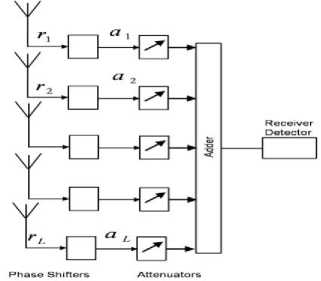
Fig. 4: block diagram of a maximum ratio combining diversity.
The output signal is a linear combination of a weighted replica of all of the received signals. It is given
L by r = ^
i = 1
a r where,
r is the received signal at receive antenna i, and a is the weighting factor for receiver antenna. In maximum ratio combining, the weighting factor of each receive antenna is chosen to be in proportion to its own signal voltage to noise power ratio. Let A and ф be the amplitude and phase of the received signal r respectively. Assuming that each receiver antenna has the same average noise power, the weighting factor a can be represented as at = Ae ф .This method is called optimum combining since it can maximize the output SNR
-
V. ALAMOUTI’S TRANSMIT DIVERSITY SCHEME
In past receiver diversity was widely used. This was on account of the fact that the receiver diversity was simpler and also the receiving devices were generally passive producing little or no interference. Transmitter diversity was difficult because of the following two reasons:
1)The multiple signals from the transmitting end would combine to produce only one value of signal level at a given point, resulting in no diversity.
2)The transmitted signals would sometimes produce objectionable nulls in the radiation at some angles.
Alamouti proposed a remarkable diversity scheme in [8] utilizing both space and time diversity known as space time coding. The new transmit diversity proposed by Alamouti in [8] states that “Using two transmitter antennas and one receiver antenna the scheme provides the same diversity order as maximal-ratio receiver combining (MRRC) with one transmitter antenna, and two receiver antennas”. The salient features associated with this diversity scheme are described as follows:
1)Redundancy is applied in space across multiple antennas, not in time or frequency, which implies that it doesn’t require any bandwidth expansion.
2)It doesn’t need any feedback from the receiver to the T X .
3)Its computation complexity is similar to MRRC.
4)Two transmitter antennas and M receiver antennas provides a diversity order of 2M .
A. Two Transmitters and One Receiver Scheme
The block diagram of Alamouti’s diversity scheme for two transmitters and one receiver is illustrated in Fig. 5.
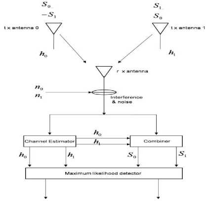
Fig. 5: two-branch transmit diversity scheme with one receiver.
Here s , s are data which are complex in nature.
At transmitting antenna 0
A= [ s 0 -s 1 * ] (5)
And transmitting antenna 1
B = [ s 0 s 1 * ] (6)
We use the property of orthogonality ( A . BT = 0 ) because there is no co-phasing in the channel, if h , h are the channels between the transmit antenna and the receiver, antennas 0 and 1 respectively. Then h = a e J 6 0 where a e J 6 0 is the channel state information and similarly h = 0 е J 6 1 .Now r , r are Gaussian distributed, the maximum likelihood decision rule at the receiver for these received signals.
Then
Where n and n represent complex noise and interference
Now the using of combiner then signal estimate is:
Now finally the receiver combining scheme for two-branch MRRC is as follows:
-
VI. SIMULATION RESULTS
In this section simulation scheme and result highlighted.
are
50 = h0 * r0 + hr * = (a2 + a2) 5o + h * n + hn *
And
A. BPSK Scheme
BPSK is simplest shift keying scheme. It uses
two
5j = (a2+a2) 5i—ho * n+h * n
phases which are separated by 180° and also termed 2-PSK.
Where ( a 2 + a 2) is second order diversity.
B. One Transmitter and Two Receivers Scheme
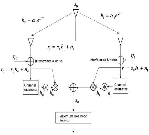
Fig. 6: Two-branch MRRC.
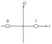
Fig. 7: phase-shift keying (BPSK).
This modulation is the most robust of all the PSKs since it takes the highest level of noise or distortion to make the demodulator reach an incorrect decision. It is, however, only able to modulate at 1 bit/symbol and so is unsuitable for high data-rate applications. The general form for BPSK follows the equation:
5n (t) =

cos(2 ” ft + n[1 — n ]), n = 0,1
This yields two phases, 0 and π. In the specific form, binary data is often conveyed with the following signals:
5 0( t ) =

cos(2 n ft + П ) for binary "0"
The block diagram of Alamouti’s proposed scheme in regarding one transmitter and two receivers is shown in Fig. 6.
[ r0 Г ] = [ h0 h ][5 0 ] + [ n 0 n1 ]
2E
5 , ( t ) = ---- cos(2 n f t ) for binary " 1"
1 Tb c
where f c is the frequency of the carrier-wave.
During the simulation, following assumptions are made:
Noise and interference are added at the two receivers. The resulting received baseband and signals are:
Then r0 = h050 + n0
And
Г = h50 + n
where h = a e J 0 0 , h = a e J 0 •
Now finally the receiver combining scheme for two-branch MRRC is as follows:
-
5 0 = h 0* r 0 + h 1* r 1
=(a2+a2) 5q+ho * no+hn *
1)The total transmitter power from the two antennas is the same as the transmit power from the single transmit antenna for MRRC.
2)The amplitudes of fading from each transmit antenna to each receiving antenna are mutually uncorrelated, Rayleigh distributed and that the average signal powers at each receive antenna from each transmit antenna are the same.
3)The receiver has perfect knowledge of the channel.
4)The transmitted signal is BPSK with equal error probabilities for both logic 1 and logic 0. As far as the simulation method is concerned the Monte Carlo simulation technique is adopted with a sample size of 106. The number of transmitting and receiving antennas is allocated. The SNR values are generated. After that the normalized valued of the variance is calculated. The Rayleigh fading channel is modeled and error is counted by transmitting the
BPSK symbol. The BER is then subsequently calculated and plotted against the SNR.
In Fig. 8, the simulation results are presented along with the theoretical results. The theoretical results are presented while considering the 1 T xx and 1 R xx, 1 T xx and 2 R xx using maximum ratio combining technique. As shown in the Fig. 8, the performance in term of BER improves significantly for example for E b /N 0 equals to 10 db the BER improves by a factor of 10. Hence, MRC schemes provide very good results; this is also an agreement with theoretical results. However, in MRC scheme, to receive better signal quality more than two receivers may require. To counteract this Alamouti proposed a scheme in which more than one transmitter can be used to transmit signals, as signal generated from these antenna’s will travel different path, hence may provide better quality signal at the receiver. As this scheme is somewhat compromising scheme, therefore results may not be up to the level of MRC. However, this scheme is very simple and has potential to combat with fading of the channel.
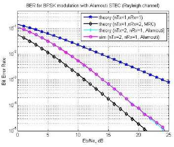
Fig.8: Performance analysis of SISO theoretical (1Tx,1Rx), SIMO Maximum ratio combining theoretical (1T x , 2 R x ), MISO Alamouti theoretical (2Tx, 1Rx) and Alamouti simulation (2Tx, 1Rx) system.
In Fig. 9, simulation results for the Alamouti scheme are presented. Here, the simulation results exactly matched with theoretical results. In Fig. 9, Alamouti results are presented while considering, 2 T xx and 2 R xx . It is evident form (Fig. 8 and Fig. 9) as the number of receiver increased from 1 to 2 the BER improves. This is understandable as the number of receiver increases the performance should improve. Comparing Fig. 8 and 9 it is noticeable that in case of 2 T x and 2 R x the results are better in comparison to 1T xx and 2 R xx MRC scheme. This 2 T xx and 2 R xx , scheme avails the advantage MRC as well as Almouti scheme.
Comparing (Fig. 8 and Fig. 9) while considering only MRC scheme at E b /N 0 equal to 10 dB, the BER is of the order of 10 3 while for 1T xx and 2 R xx and for 1T xx and 4 R xx , the BER is of the order of 10 5 , this is very significant improvement. However, this does not mean that if we keep on increasing the receiver the BER performance will improve continuously.
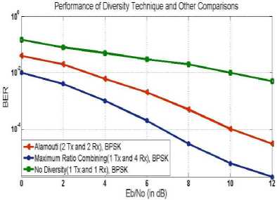
Fig. 9: Performance analysis of SISO (No diversity (1T x , 1R x ), BPSK), MIMO (Alamouti (2Tx, 2Rx), BPSK) and Maximum ratio combining (1Tx, 4Rx), BPSK) system.
In general the signal st ( t ) , i G (0,1) is transmitted,
2E where, So(t) = ---- cos(2n ft + П) for binary "0".
Tb c
2E
S j ( t ) = --- - cos(2 n f t ) for binary "1", with equal
This method will maintain the average power to a constant level. In the simulation, we modified the generation of the symbol by S ( t ) = [ P • S o ( t ) + (1 — P ). S i ( t ) ] where p is random number between 0 and 1 and the obtained results are shown in Fig. 10 and Fig. 11.
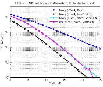
Fig.10: Performance analysis of SISO theoretical (1T x , 1R x ), SIMO Maximum ratio combining theoretical (1Tx, 2 Rx), MISO Alamouti theoretical (2Tx, 1Rx) and Alamouti simulation (2Tx, 1Rx) system for p = 0.4.
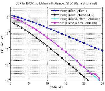
Fig.11: Performance analysis of SISO theoretical (1T x , 1R x ), SIMO Maximum ratio combining theoretical (1Tx, 2 Rx), MISO Alamouti theoretical (2Tx, 1Rx) and Alamouti simulation (2Tx, 1Rx) system for p = 0.8.
antenna diversity,” in Proc. 1993 IEEE Vehicular Technology Conf. (VTC 43rd), May 1993, pp. 508– 511.
-
[6] G. G. Raleigh and J. M. Cioffi, “Spatio-Temporal Coding for Wireless communication”, IEEE Transaction on Communication, Vol. 46, No. 3, pp. 357-366, March 1998.
-
[7] B. Vucetic and J. Yuan, Space-Time Coding, England, Wiley, 2003.
-
[8] S. Alamouti, “Space block coding: A simple transmitter diversity technique for wireless communications,” IEEE J. Select. Areas. Commun., vol. 16, pp. 1451–1458, Oct. 1998.
References Comparison of Wireless MIMO System Under Alamouti's Scheme and Maximum Ratio Combining Technique
- W. C. Jakes, Ed., Microwave Mobile Communications. New York:Wiley, 1974.
- A. Wittneben, "Base station modulation diversity for digital SIMULCAST,"in Proc. 1991 IEEE Vehicular Technology Conf. (VTC 41st),May 1991, pp. 848–853.
- A. Wittneben, "A new bandwidth efficient transmit antenna modulationdiversity scheme for linear digital modulation," in Proc. 1993IEEE International Conf. Communications (ICC'93), May 1993, pp.1630–1634.
- J. H. Winters, "The diversity gain of transmit diversity in wireless systems with Rayleigh fading," in Proc. 1994 ICC/SUPERCOMM, New Orleans, LA, May 1994, vol. 2, pp. 1121–1125.
- N. Seshadri and J. H. Winters, "Two signaling schemes for improving the error performance of FDD transmission systems using transmitter antenna diversity," in Proc. 1993 IEEE Vehicular Technology Conf. (VTC 43rd), May 1993, pp. 508–511.
- G. G. Raleigh and J. M. Cioffi, "Spatio-Temporal Coding for Wireless communication", IEEE Transaction on Communication, Vol. 46, No. 3, pp. 357-366, March 1998.
- B. Vucetic and J. Yuan, Space-Time Coding, England, Wiley, 2003.
- S. Alamouti, "Space block coding: A simple transmitter diversity technique for wireless communications," IEEE J. Select. Areas. Commun., vol. 16, pp. 1451–1458, Oct. 1998.
