Compensation of thermal deformations of heat supply network with radial expansion bends

Author: Lipovka Yury L., Belilovets Vitaly I.
Journal: Журнал Сибирского федерального университета. Серия: Техника и технологии @technologies-sfu
Article in issue: 5 т.11, 2018.
Free access
A methodology for structural analysis of compensation of thermal expansions used for channel or aboveground sections of heat network pipelines with radial expansion bends has been proposed. The methodology is based on the methods of structural mechanics and allows to find technically based dimensions of radial expansion bends. Increased flexibility of the heat pipe angles and stress-raisers of additional bending stresses have been taken into account, the functional and graphical dependencies of the stress caused by thermal deformations of the heat pipe section with the U-shaped radial expansion bends on the temperature of the coolant have been presented. The authors developed and presented the computer program used for calculating radial expansion bends. Due to the program analyzing the model of a heat pipe section with a radial U-shaped expansion bend has been calculated. Comparison of the calculation results with the results obtained by means of the well-known software system “Start” developed by the scientific-and-technological enterprise “Pipeline” has shown a sufficient convergence of results, which confirms the efficiency of the presented methodology and computer program.
Heat supply network, thermal expansions of heat pipes, compensation of thermal pipe deformations, radial expansion bends
Short address: https://sciup.org/146279541
IDR: 146279541 | UDC: 624.042.12 | DOI: 10.17516/1999-494X-0059
Компенсация температурных деформаций теплопроводов с радиальными компенсаторами
Предложена методика расчета компенсации температурных расширений для канальных или надземных участков трубопроводов тепловых сетей с радиальными компенсаторами. Методика основана на методах строительной механики и позволяет подобрать технически обоснованные габариты радиальных компенсаторов. Учтены повышенная гибкость отводов теплопроводов и концентраторы дополнительных изгибных напряжений, изложены функциональные и графические зависимости напряжения температурных деформаций участка теплопровода с П-образным радиальным компенсатором от температуры теплоносителя. Представлена разработанная авторами статьи компьютерная программа для расчета радиальных компенсаторов, с использованием которой проведен расчет модели участка теплопровода с радиальным П-образным компенсатором. Сравнение результатов расчета с результатами, полученными при помощи известной программной системы «Старт», разработанной научно техническим предприятием «Трубопровод», показало достаточную сходимость результатов, что подтверждает работоспособность представленной методики и компьютерной программы.
Text of the scientific article Compensation of thermal deformations of heat supply network with radial expansion bends
Computational simulation with a georeference of networks location, without which it is impossible to calculate the operating modes of district heating pipelines correctly, has been the main concern of the following papers [9-11]. The solution of new, rather complex tasks in the field of transportation of energy sources can contribute to cyber-physical systems [12] and cloud-based computing [13].
Scalable parallel computation of finite element models can be also an effective tool for managing network operation modes in complex geological conditions of modeling used in geotechnical engineering [14].
Optimizing route location of urban power grids is certain to be one of the most important tasks, ensuring a reduction in capital investments in district heating networks [15].
Remote-controlled regulating devices allow to communicate with power suppliers on-line, but this requires a radical rethinking of existing control algorithms. In [16-18], the results of simulating the distributed systems in terms of transportation of power for heating needs, ventilation and air conditioning (HVAC), have been presented.
One of the most important tasks of optimizing the transportation system of power sources is certain to minimize the power consumption of pumps and heat losses in the pipeline network. The solution of this problem by means of the nonlinear programming algorithm (NPA) and the genetic algorithm (GA) has been described in [19]. The research results of the dynamic characteristics of the thermal regimes of district heating systems due to dynamic modeling method have been presented [20].
Methods
Methods of structural mechanics allow to perform structural analysis of the heat supply network to loads and imposed deformations, including compensation for thermal expansions. The most commonly used method is the force method. In order to calculate heat pipes for thermal expansion there is a modification of the force method, called the elastic center method. Structural analysis of expansion bends for thermal effects by the elastic center method are considered in [21, 22]. It should be noted that, in terms of structural mechanics, the heat pipe is a statically indeterminate system. The assigned task is to disclose this static indeterminacy. In case of using the force method, the disclosure of static indeterminacy occurs due to eliminating of primary system from redundant constraints and their replacement by a statically determinate primary system. Unknown reactions of eliminated redundant constraints are determined by forces and moments. Displacements for each of eliminated redundant constraints are equal to zero. Primary unknowns are forces in eliminated redundant constraints, which are calculated on the basis that corresponding displacement to each constraint are equal to zero.
Let us consider a section of a heat pipe bounded by two fixed supports (Fig. 1 a ). In terms of structural mechanics, this section is a three times statically indeterminate system. The eliminated fixed support is placed at the origin of an XY-coordinate system. The second fixed support is shown as B. Reactions of the eliminated redundant constraints X1, X2, X3 are positive.
Generally speaking, for a common flat section of a heat pipe, primary system is determined by eliminating constraints for one of the fixed and all sliding supports. The eliminated redundant constraints are replaced by unknown forces and moments. Subsequently it is required to find generalized forces. In the meantime, it should be assumed that displacements caused by the generalized forces in primary system do not violate restrictions imposed by redundant constraints on given system.
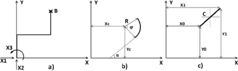
Fig. 1. Design piping diagrams
Problem conditions under consideration can be expressed as the following system of equations, called the system of canonical equations of the force method
(S11X1 + S12X2 + S13X3 + - + SlkXk + Д1= 0;
{S21X1 + S22X2 + S23X3 + - + S2kXk + Д2= 0; (1)
5i1X1 + Si2X2 + 5,3X3 + - + SikXk + Д;= 0, where δ11, δ12, …, δ1k, …, δ21, δ22, …, δik – are the unit displacements of primary system; X1, X2, X3, …, Xk – are the primary unknowns; Δ1, Δ2, …, Δi – are the free terms of the canonical equations. These terms represent generalized displacements in primary system, which correspond to the generalized force Xi. External loading, temperature differences, displacement of the supports, pre-tensioning of pipelines are responsible for these displacements.
The free terms are determined on the basis of the following dependences
Ai = Alt + Aim + д1о + д1р;
A2 = A2t + Д2М + Д20 + Д2р; Д3 = Aa0 + Aap, where Δ1, Δ2, Δ3 – are the displacements of application points of the corresponding unknown forces X1, X2, X3 in the direction of these forces (Fig. 1a); Δ1t, Δ2t – are the thermal expansions of pipes; Δ1M, Δ2M – reduced to the origin coordinates components of the displacement in the direction of the forces X1, X2 from pre-compression (for pre-tension, displacements are negative); Δ10, Δ20, Δα0 – are the linear and angular displacements, which are caused by displacement of supports; Δ1p, Δ2p, Δαp – are the displacements that correspond to unknown Xi arising in primary system as a result of external loading.
The thermal expansions of pipes are calculated as follows
Дц= -LxaAt; Д21= -LyaAt, (3)
where L x , L y – are the projections on the x, y axis of distance between end supports (Fig. 1 a ); α – is the linear expansion coefficient of pipe material for specified temperature of pipe wall; Δt – is the temperature difference.
The negative sign in equations (3) is responsible for process of the thermal expansion of the pipeline. With decreasing temperature, equations (3) are positive, since the reverse process occurs. The point of reference of the change in temperature is the temperature at which the installation of the heat pipe is completed.
The linear and angular displacements caused by displacement of supports are determined by the following equations
Аю = A Ao - A Bo + yB aB ; A 20 = A Ao - A B 0 + x^ B ; Aa o = AaA + AaB , (4)
where Δ10, Δ20, Δα0 – are the linear and angular displacements caused by displacement of the supports; A A 0, A A 0, Aa A - are the positive displacements of the eliminated support A (Fig. 1 a ) in the direction of the unknowns X1, X2, X3, respectively; A B 0, A B 0, Aa B - are the positive displacements of the support B in the same directions; x B , y B – are the coordinates of the support B.
The displacements that correspond to the unknown Xi in primary system from external loading are calculated by the Mohr’s Integral .
For a flat heat pipe consisting of n elements, we can write the following equations
. гL, M1Mp L, M2Mp L M3Mp lp /о 61 ■ 2P ;° E1 ■ap Jo 61
where M15 M2, M3 - are the bending moments in an arbitrary section of primary system, caused by action of the unit forces X15 X2, X3 respectively; Mp - is the bending moment in the same section, caused by external loading; k – is the pipe flexibility factor; EI – is the pipe stiffness factor.
The number of canonical equations corresponds to the degree of system static indeterminacy. The coefficients of the equations δik contain data about the displacements of application points of the unknown forces in the direction of their action caused by unit forces or moments. The first of the displacement indices δik represents the unknown force number Xi which given generalized displacement corresponds to; the second index is the number of unit force that would cause this displacement. The displacement δik corresponds to the force Xi, when Xiδik is the work of the force Xi on the displacement δ ik . The coefficient Δ i is the displacement of the application point of the force X i in the direction of its action, which is caused by external loading, temperature differences, displacement of the supports and pre-tension of the heat pipe.
If we do not take into account effect of longitudinal and transverse forces on the displacement, only taking into account bending and torsion, Mohr’s formula for the three-dimensional section of the pipeline, consisting of n-elements, will have the following form
8ik = S jLi J0L i k» dL + ^ J0L i H^ dL . , (6)
where M i – is the bending moment in an arbitrary section of primary system from the action of the unit generalized force Xi = 1; Mk – is the bending moment in the same section from Mi; Hi – is the torque in an arbitrary section of primary system from the force X i = 1; H k – is the torque in the same section from the force Xk = 1; E – is the modulus of elasticity of pipe material; G – is the shear modulus of pipe material; I – is the moment of inertia of pipe cross-section; I p – is the polar moment of inertia of pipe cross-section; L – is the length of the pipeline element; k – is the pipe flexibility factor.
For a flat heat pipe, in the absence of torsion, formula (6) can be transformed to the following form
5 ;k = Z jLi Jo1 k— et^ dLp (7)
For a common flat heat pipe section, the coefficients of the canonical equations are determined by the sum of the Mohr’s integrals over the length of each element. The equations under consideration can be expressed as follows
L 2 L 2
5 11 = №dL; 8 22=Z/kEidL; 8 33=2/шаь;
ООО
513 = -ULkgdL; 52b = "^М^ 53i = S^dL.
If the heat pipe section includes pipes of different cross-sections, the stiffness value EI will differ for each of the section elements. Taking this into account, it is necessary to introduce notion of the reduced flexibility factor. This flexibility factor is denoted by the symbol η and expressed as follows
П = kEEf, where k – is the flexibility factor; EI0 – is the element with the greatest stiffness value; EI – is the stiffness value of given element.
Considering this, the determined integrals in formulas (8) take the meaning of the geometric characteristics of the reduced length of the center line for heat pipe elements. The free terms of the canonical equations system will express as follows
A; = A1EI0; A2 = A2EI0; A3 = A3EI0.
The reduced moments of inertia relative to the axes X, Y are calculated by formulas
Jxi pr = JnLy2ndL; Jyi pr = LLx2ndL.
The reduced inertia product
JxyJ pr = J„LxyndL.
The reduced static moments relative to the X, Y axes
Sx,i pr = JoyndL; Sy,i pr = JoxndL.
The reduced length of the centerline of the element
L pr = /«L ndL nL,.
In expressions (11) – (14) i displays the element number, L – the length, m; η – reduced the flexibility factor.
In order to calculate by formulas (11) – (14), the centerline of the heat pipe should be divided into elements with constant bending stiffness and curvature. Further on we need to define the initial and final coordinates of each element, its reduced flexibility factor and the reduced length.
In Fig. 1 b , the central axes of the element (α, β) are drawn parallel to the given axes X, Y. Therefore the moments of inertia for any element relative to the axes X, Y can be calculated by formulas
«
14 „-ly pr + L . рг У , ; J y.,рг-lti pp + L , „X , . (15)
The reduced product of inertia of the i-th element is determined by the formula
J xy,i pr J ae,i pr + L i pr x i y f
where L i pr - is the reduced length of the element, m; x; - is the coordinate of the straight element center ofgravity relative to the X axis, m; y; - is the coordinate of the straight element center of gravity relative to the Y axis, m; Jα,i pr, J β ,i pr – are the reduced moments of inertia of the i-th element relative to the eigen central axes α, β; J αβ,i pr – is the reduced product of inertia of the i-th element relative to the eigen central axes α, β.
The coordinates of the center of gravity relative to the X, Y axes (Fig. 1 b ) are determined by the following expressions
Х;=|(х1Д + ХоД);у;=|(у1Д+УоД).
The ratio for the reduced length of the heat pipe is as follows
L „ = nJ(xu-x ., i)2+ (yu-yw)2.
The reduced moments of inertia relative to the eigen central axes is determined by the following __
L,i pr = ~ L pr (xi,i - X0,i) ; J^ pr = - Li pr (у1Д - y0,i) .
The reduced product of inertia relative to the eigen central axes is determined by the following formula
J a,i pr=^ L i pr (x l,i
-хОД)(у1Д—уоД).
Thus, given geometric characteristics for the straight elements of the heat pipe are determined as follows the reduced moments of inertia of the i-th element
J x,i pr L i pr
£l:
J y,i pr = L i pr
(x
—
A 2 xo.i)
+
r . Л (xi,i +xo,i)
;
the reduced product of inertia of the i-th element
T _ J Г (x i,i -X o,i )(y i,i -yo ,i ) (x1 ,i +X o,i )(y1 ,i +yo ,i ) l
Jxy,i pr Li pr[ 12 + 4 J.
The reduced static moments of the i-th straight element can be determined by the following formulas
Sx ,i pr = L i рг У ;
j L i рг (У 1д +У од ); Sy ,i pr
= Li prxi = 2 Li pr(x1,i + x0,i). (23)
Fig. 1 c shows the curvilinear element of the heat pipe in the XY coordinate system. The coordinates of the center of curvature of the element are denoted by Xc, Yc. The radius of curvature is denoted by R. The central angle of the element is denoted by φ. The angle of inclination of the initial tangent to the positive direction of the X axis is denoted by α.
The reduced moment of inertia and product of inertia of the i-th curvilinear element located arbitrarily are determined by the following equations
Iti „ = к, pr^-ZR^ + R,^); (24)
J "-R1
ITipr = Ri ,^-R^^
where xc i, yc i – are the coordinates of curvature center of the longitudinal axis of the i-th curvilinear ,, element, m; Ri – is the radius of curvature of the longitudinal axis of the i-th curvilinear element, m; Ri pr – is the reduced radius of curvature
Ri pr = nRi-
The reduced length is calculated by formula
Li pr = Ri prCi.
The reduced static moments are calculated by formulas
S x,i pr = R i рА У сдЧ R i C 2 j; S y,i pr = R i P r lx c,i C l + R i C 3 ).
The values of the coefficients Ci are determined by the following expressions ф^. + ф); C^. Ф,,(„ + ф);
C4 = 0,5[Ф + slnФ cos(2 a + ф )] ; C5 = 0,51Ф - slnФ cos(2 a + ф )] ;
C6 = 0,5sinф sin(2a + Ф).
In expressions (28), the angles α and φ are considered in radians.
All the coefficients of the canonical equations were multiplied by EI 0 = const. It follows that EI0δik = δik*. Thus, the formula of the canonical equations coefficients by given geometrical characteristics of a simple flat heat pipe composed of n elements will be as follows
511* = ^1Jx ,i pr; 322* = ^1Jy , i pr; 533* = ^1Li pr; (29)
1^1 УД Pr' 3 1
n
У S ■
^Sx'i pr- i=1
5 i2* = -yj xy,ip r; s23 *
1^1
The system of canonical equations for the calculated section of the heat pipe be transposed to the following form
L511 - X1+':'T: ': ' X + < о
< 521 X1 + 522 X2 + 523 Хз + A2 = 0,
(5 31* X 1 + 532% + 533% + A3 = 0,
Applying Cramer’s formulas, solution of system (30) can be represented as follows
D1 D2
X1 = D ; X2 = D ; X3 = D, where D – is the determinant of the coefficient matrix of the system (30); D1, D2, D3 – is the determinants obtained from D by replacing the corresponding column of the coefficients δik* by free terms column.
The determinants D 1 , D 2 , D 3 are defined by the following formulas
* * * * * *
1 — A1 a 1 + A2a4 + A3a5 ; D 2 = A1a4 + A2a2 + A3 a 6 ;
D3 — A^ + Va. + А3аз, where a1, a2, a3, a4, a5, a6 – are the constants.
The determinant D is calculated by formula
D — 8п * а 1 + 5 i2* a 4 + 8B * a 5 . (33)
The constants a1, a2, a3, a4, a5, a6 are determined by the following formulas ai — 822*833* - 833*2; a2 — 811*833* - 813*2; аз — §11*822* - 812*2;
a 4 — 813*832* — 812*833* ; a 5 — 812*823* — 813*822* ;
a 6 — 821*813* - 823*811* .
It is necessary to consider analysis of the pipe flexibility factor in more detail. In the beginning of the 20th century the classical solution for bending curved pipes (bends) was published by T. Karman. In this solution, an energy approach with the subsequent solution of the problem by the Ritz method was used. The solution was a trigonometric series. With the neglecting of all members of the series, except for the first, a formula for the flexibility factor (Karman’s formula) for curved pipes in bending was derived. This formula has the following form
-
1 + Ш2 10+12X 2 '
where k – is the flexibility factor of the curved pipe (bend); λ – is the geometric characteristic of the curved pipe, defined as follows
. — 4R8
— (D □ -8) 2 '
where R - is the radius of curvature of the curved pipe, mm; D □ - is the outer diameter of the curved pipe, mm; δ – is the wall thickness of the curved pipe, mm.
If we neglect all the members of the series except the first two, we obtain the Karman formula in the second approximation for calculating the flexibility factor, having the form
3+536^ 2 +3600^ 4 105+4136^ 2 +4800X 4 .
The formula in the third approximation is defined similarly
3 +3280X 2 +3 2 9 3 76 X 4 +2822400X 6 252+73912X 2 +2 446176 X 4 +2822400X 6 .
When deriving the formula for the flexibility factor, T. Karman made the following assumptions:
,
-
1) the radius of curvature of the central line of a curved pipe is much larger than the radius of a pipe . e ;
itself; 2) the wall thickness of a curved pipe is small in comparison with the radius of a pipe; 3) the displacement of the neutral axis was not taken into account; 4) the Poisson’s ratio was not taken into account; 5) the ways of fixing curved pipes with straight pipes were not taken into account; 6) the bending moment does not change along the entire length of a curved pipe; 7) the influence of internal excess pressure was not taken into account.
The bending of curved pipes was investigated by R. Clark and I. Reissner. A solution of this problem was obtained, by analyzing the differential equations, when considering the bending of – 612 – curved pipes from the point of view of the theory of thin-walled shells. By the method of asymptotic integration, the following formula for the flexibility factor k = 2k/^12(1 - ц2) , (39)
where λ – is the geometric characteristic of the curved pipe; μ – is the Poisson’s ratio.
If we assume a Poisson ratio to be equal to 0.3, then the Clarke and Reissner formula can be represented as follows k = -^7, (40)
'.
The R. Clark and I. Reissner formula gives a more precise value of the flexibility factor of curved pipes than the T. Karman’s formulas for λ < 0.3.
At the present day, a great number of different works has been devoted to solving the problems of calculating pipe bends. For example, in [23-24] analytical solutions for the bending of pipes are considered. In [25] the solution for the bending of pipes using the finite element method is presented.
Results and Discussion
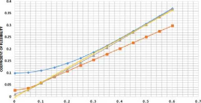
The Karman’s formula and formula of Clark and Reissner were investigated. The graph of the dependences of the change in the flexibility factor on the geometric characteristic of a curved pipe for three Karman approximations and the Clarke and Reissner formulas are constructed.
Analysis of the graphs in Fig. 2 gives the following results. Firstly, the larger is the wall thickness of a curved pipe, the flexibility factor is the closer to 1. Secondly, the Karman’s approximations are incorrectly used in determining the flexibility factor of curvilinear elements of heat pipes, since they are thin-walled structures for which their geometric characteristics will have small values. If we take the geometric characteristic of a curved pipe to be zero, then the flexibility factor for all the Karman’s approximations will have nonzero values. This is not true, since with the value of the geometric characteristic of a curved pipe are equal to zero, the flexibility factor of this pipe is similarly equal to zero. It follows that the Karman’s approximations are correctly used to determine the flexibility factor of thick-walled pipes under high internal excess pressure. If a heat supply network is considered, then the Clark and Reissner formula for determining the flexibility factor should be used.
With bending curved pipelines under the influence of forces that flatten their cross section significant local stresses arise. If the longitudinal stresses found in the conventional bending theory are denoted by σ, then the maximum longitudinal stresses can be calculated as follows
"m"=*' (41)
where i0 – is the longitudinal stress concentration factor in the curved pipe io = 02.97, (42)
x /3
where λ – is the geometric characteristic of the flexibility of the curved pipe.
It should be remembered that the local stress concentration factor is present in any places of sharp changes in the geometry of a pipeline. To these places, besides bends, you can include tees and transitions from one diameter to another. For each case, there is a definite formula for calculating this factor.
PtPFGFOMRRY
♦— First approximation
Third approximation
-e Second approximation
Formula Clarke and Reissner
Fig. 2. Dependence of the flexibility factor on the geometry of the pipe
The authors of this article have developed and registered the computer program “Calculation of the expansion bends of a heat supply network” [26]. Calculation in the program is based on the methods of structural mechanics. The program makes it possible to calculate thermal stresses for sections of a heat supply network by means of different schemes of expansion bends that are not clamped by the soil. The program provides calculation of both expansion bends and original angles of bending of a heat supply network. Based on input information entered in the input fields, calculation is performed and information on the stresses in the main sections of the configuration of the heat pipe section is displayed in the result fields. This allows you to select the optimal size of expansion bends.
Fig. 3 shows the interface of the program. As you can see, the window is divided into 3 blocks: configuration selection, initial data and results. The configuration selection block allows you to select one of the 8 circuits of a heat pipe section with an expansion bend or an original angle of bending for subsequent calculation. Thus, it is possible to calculate the symmetrical and asymmetrical scheme of U-shaped and L-shaped expansion bends, Z-shaped and L-shaped expansion bends with angles of bending of 90 or more degrees. The whole program is built on the basis of methods of structural mechanics, applied to a heat supply network. Accordingly, the program takes into account the increased flexibility of heat pipe bends.
Let us consider comparison between the results of calculation on thermal expansions of a section of a heat pipe with the U-shaped expansion bend (loop), received by means of the presented program, and the results of the program system “Start”. The section is bounded by fixed supports. We take the following initial data: the pipeline 159x4.5 mm, steel 09G2S; the installation temperature minus 40 °C; the temperature of the heat transfer plus 150 °C; the working pressure 1.6 MPa; the density of heat transfer 1000 kg/m3. The section has the following dimensions: the radius of bend 240 mm; the loop shoulders length 8 m; the loop legs length 4 m; the loop back width 4 m. After the calculations, the following results were obtained: the minimum stresses on the section (in the loop shoulders) was 8.9 MPa for the author’s program and 9.5 MPa for the Start; the stress in the loop legs was 23.8 MPa for – 614 –
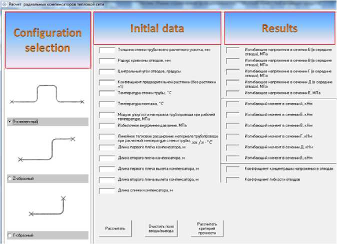
Fig. 3. Interface of the program Calculation of expansion bends
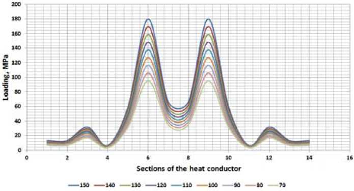
Fig. 4. Temperature dependences of a heat pipe section with the U-shaped expansion bend the author’s program and 24.5 MPa for the “Start”; the maximum stress in the loop back was 47.9 MPa for the author’s program and 48.2 MPa for the “Start”. Due to this experiment, we can conclude that the calculation in the computer program “Calculation of the expansion bends of a heat supply network” is correct.
Let us consider the temperature dependences of a heat pipe section with an expansion bend. The results will be presented graphically.
Fig. 4 shows the temperature curves for an example of a heat-pipe section. The numbers opposite the line color show the temperature values. As we can see from the graph, the largest and smallest – 615 – stresses from thermal expansions, at any considered temperature, are in sections 6, 9 (largest) and 4, 11 (smallest). The sections with the highest stresses are in the loop back, the sections with the smallest stresses in the loop shoulders.
Conclusions
Due to the force method, a methodology for calculating the stresses based on thermal expansions for sections of heat network trenchless pipelines with radial expansion bends has been developed. In the methodology the increased flexibility of the bends has been taken into account. The optimal formula for calculating the flexibility factor of heat pipe bends has been determined. Due to developed methodology, a computer program for calculating radial expansion bends of heat networks has been developed. The efficiency of this program has been confirmed by means of comparing the results of a numerical experiment with the model of the U-shaped expansion bend with the software system “Start” developed by the scientific-and-technological enterprise “Pipeline”. The experiment used the design model of the U-shaped expansion bend made it possible to draw the following conclusions: 1) the nature of temperature stresses distribution along the expansion bend sections for any temperature of the coolant coincides; 2) the angles of the expansion bend back are the most crucial elements where the greatest stresses are observed; 3) in case of calculating the radial expansion bends, it is necessary to take into account the increased flexibility of the bends and the concentration of local stresses in them, since their ignoring will cause large inaccuracies in the results.
References Compensation of thermal deformations of heat supply network with radial expansion bends
- Белиловец В.И., Липовка А.Ю., Липовка Ю.Л. Оценка надежности городских тепловых сетей с точки зрения прочностных расчетов. Город, пригодный для жизни: материалы II Международной научно-практической конференции «Современные проблемы архитектуры, градостроительства, дизайна». красноярск: СФУ, 2015, 376-378
- Абсалямов Д.Р. Повышение надежности инженерных систем методом формализации поиска отказов. Инженерно-строительный журнал, 2012, 2(28), 39-47
- Липовка Ю.Л., Белиловец В.И. Некоторые теоретические стороны расчета температурных деформаций подземных бесканальных теплопроводов. Журнал СФУ. Техника и технологии, 2016, 9(4), 546-562
- Лалин В.В., Яваров А.В. Современные технологии расчета магистральных трубопроводов. Инженерно-строительный журнал, 2010, 3, 43-47
- Тюкалов Ю.Я. Функционал дополнительной энергии для анализа устойчивости пространственных стержневых систем. Инженерно-строительный журнал, 2017, 2(70), 18-32
- Сергеев О.А., кисилев В.Г. Сергеева С.А. Общая потеря устойчивости и оптимизация стержневых конструкций со случайными несовершенствами при ограничениях на вероятность безотказной работы. Инженерно-строительный журнал, 2013, 9(44), 30-41
- Кирсанов М.Н. Статический расчет и анализ пространственной стержневой системы. Инженерно-строительный журнал, 2011, 6(24), 28-34
- Лалин В.В., Розин Л.А., кушова Д.А. Вариационная постановка плоской задачи геометрически нелинейного деформирования и устойчивости упругих стержней. Инженерностроительный журнал, 2013, 1(36), 87-96
- Kudinov I.V., Kolesnikov S.V., Eremin A.V., Branfileva A.N. Computer models of complex multiloop branched pipeline systems. Thermal Engineering (English translation of Teploenergetika), 2013, 60 (11), 835-840
- Finney K.N., Sharifi V.N., Swithenbank J., White S., Ogden S. Developments to an existing city-wide district energy network. Part I: Identification of potential expansions using heat mapping. Energy Conversion and Management, 2012, 62, 165-175
- Kaliatka A., Valinčius M. Modeling of pipe break accident in a district heating system using RELAP5 computer code. Energy, 2012, 44(1), 813-819
- Yoo H., Shon T. Challenges and research directions for heterogeneous cyber-physical system based on IEC 61850: Vulnerabilities, security requirements, and security architecture. Future Generation Computer Systems, 2016, 61, 128-136
- Jararweh Y., Al-Ayyoub M., Darabseh A., Benkhelifa E., Vouk M., Rindos A. Software defined cloud: Survey, system and evaluation. Future Generation Computer Systems, 2016, 58, 56-74
- Zhang Y.L., Tan F., Zhang L.R., Shi M.M. Scalable parallel computation for finite element model with hundreds of millions of elements in geotechnical engineering. Rock and Soil Mechanics, 2016, 37(11), 3309-3316
- Morvaj B., Evins R., Carmeliet J. Optimising urban Energy systems: Simultaneous system sizing, operation and district heating network layout. Energy, 2016, 16, 619-636
- Maasoumy M., Nuzzo P., Sangiovanni-Vincentelli A. Smart buildings in the smart grid: Contract-based design of an integrated energy management system. Power Systems. 2015, 79, 103-132
- Radhakrishnan N., Su Y., Su R., Poolla K. Token based scheduling for energy management in building HVAC systems. Applied Energy, 2016, 173, 67-79
- Reppa V., Papadopoulos P., Polycarpou M.M., Panayiotou C.G. A Distributed Architecture for HVAC Sensor Fault Detection and Isolation. IEEE Transactions on Control Systems Technology, 2015, 23(4), 1323-1337
- Zhou S., Zhao Y., Zhang C., Zhang L. Operational optimization and algorithm of Hot-Water district heating system. ICIC Express Letters, 2015, 9(5), 1519-1524
- Zhou S., Tian M., Zhao Y., Guo M. Dynamic modeling of thermal conditions for hot-water district-heating networks. Journal of Hydrodynamics, 2014, 26(4), 531-537
- Lipovka Yu.L., Belilovets V.I., Lipovka A.Yu. The influence of slenderness ratio and stress concentration in taps on load calculations to thermal expansion in П -shaped compensators of thermal network. J. Sib. Fed. Univ. Eng. Technol, 2015, 8(1), 11-32
- Belilovets V.I. The Influence Factors of Flexibility and Stress Concentration in the Taps to the Calculation of Cooling Strain of Radial Compensators in Heat Supply Network. Prospekt Svobodny -2015: Proceedings of the scientific conference dedicated to the 70th anniversary of the Great Victory, Krasnoyarsk, SibFU, 2015, 11-15
- Radchenko S.A. Analytical and numerical solution for а elastic pipe bend at in-plane bending with consideration for the end effect. International Journal of Solids and Structures, 2007, 44, 1488-1510
- Kolesnikov A.M. Large bending deformations of pressurized curved tubes. Arch. Mech, 2011, 63, 507-516
- Fonseca E.M.M., FJM. Q. de Melo and Madureira M.L.R. A Multi-nodal Ring Finite Eleinent for Analysis of Pipe Deflection. International Journal of Manufacturing Science and Engineering, 2011, 2(2), 109-114
- Свидетельство о государственной регистрации программы для ЭВМ № 2014615580. Расчет радиальных компенсаторов тепловой сети. Белиловец В.И., Липовка Ю.Л., дата поступления 31.03.2014. Дата регистрации 29.05.2014
