Conducting a synthesis of a digital automaton for an automated firefighting system

Free access
Every year the industry in the world is gaining momentum: the number of industrial enterprises is growing, and with it the number of accidents at them. Oil today is the most common product for the synthesis and production of products. Increasing the level of fire protection systems at oil refineries remains one of the most important components of protecting people from technogenic hazards. The speed of innovation allows the application of artificial intelligence in the creation of automated fire protection systems. Research objective. This study is aimed at building a model of an automated integrated fire protection system (AISPPO).Through the synthesis of digital automata and minimizing the control functions of the digital model is created a system of automated integrated fire protection system. Materials and methods. To solve the problems of research used methods of constructing graphical algorithms of automated integrated fire protection system. This system is a new approach to solving the issue of safety of industrial facilities in the oil refining industry. Results. The proposed new model of the software implementation of a digital automaton in an automated integrated system of fire detection and monitoring of an oil refinery has made it possible to create a bank of calculated and analytical data on all potential types of failures in the structure of the enterprise in order to train personnel and make changes to existing methodological documents and instructions for personnel actions in a particular situation. Conclusion. The developed technology allows you to process the incoming signal contained in cyclograms into an intermediate form for the synthesis of digital automata using innovative tools.
Mili automaton, digital automaton, graph, graph vertex, minimization of logic function
Short address: https://sciup.org/147233799
IDR: 147233799 | UDC: 519.713 | DOI: 10.14529/ctcr210105
Проведение синтеза цифрового автомата для автоматизированной системы пожаротушения
Повышение уровня систем противопожарной защиты НПЗ остается одной из важнейших составных частей обеспечения защиты населения от угроз техногенного характера. Скорость развития инноваций позволяет применить искусственный интеллект при создании автоматизированных систем пожарной безопасности. Цель исследования. Данное исследование направлено на построение модели автоматизированной интегрированной системы управления противопожарной защитой (АИСУПЗ). Материалы и методы. Для решения задач исследования использованы методы построения графов, задание графов алгоритмом работы автоматизированной интегрированной системы противопожарной зашиты. Данная система является новым подходом к решению вопроса безопасности промышленных объектов нефтеперерабатывающей отрасли. Результаты. Предложенная новая модель программной реализация цифрового автомата в автоматизированной интегрированной системе обнаружения и мониторинга пожара нефтеперерабатывающего предприятия дала возможность создать банк расчетных и аналитических данных по всем потенциально возможным видам разрушения конструкции установки с целью подготовки персонала и внесения изменений в действующие руководящие документы и инструкции по действиям персонала в конкретной ситуации. Заключение. Разработанная технология дает возможность обработки поступающего сигнала, содержащегося на циклограммах, в промежуточную форму для синтеза цифровых автоматов при помощи инновационных инструментальных средств.
Text of the scientific article Conducting a synthesis of a digital automaton for an automated firefighting system
The model of a digital automaton (CA) of an automated firefighting system with input and output signals induces a one-to-one mapping of the set of commands in the input signals (the input command mapping) into the set of commands in the output signals. In this article we consider the stages of solving the problem of synthesizing automata by the mappings induced by them.
According to the developed algorithm (Fig. 1), when selecting the states, one should take into account such recommendations as:
– the correspondence of the set and the initial set;
– the choice of the next state is made according to the ascending order after each PROCESS block;
– before each DECISION block, after each line adjacency point, which indicates the transition direction [1] .
Refinery accident and fire analysis
According to the developed functioning algorithm decided that the scheme of the CA model of the automated fire suppression system (AFS) will include 14 a 0 , a 1 , a 2 , ..., a 13 states, where a 0 - the initial state [2].
All 14 states of digital automaton will be encoded by four-bit binary numbers (Tables 1–3). The memory block, in this case, will be a four-bit parallel register on D-triggers, because storage of each bit of the binary code will use one trigger [3, 14].
Based on the developed algorithm of functioning of the digital automaton ASFT we build a graph [4]. The state of the device in the graph will depend proportionally on the values of the vertices (vertices of the graph). The vertices of the graph of the ASPT CA model are connected by arcs, which show the direction of transition. At the top of the arcs we write transition conditions and output signals [5, 11, 12].
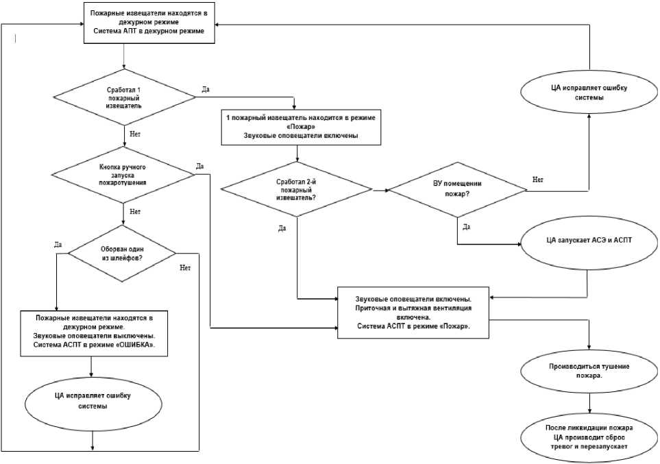
Fig. 1. Algorithm of automatic fire extinguishing system operation at an industrial facility
Table 1
Assignment of values to the states of the digital automata model of the automatic fire-fighting system
|
State of the machine |
Status deciphering |
|
a 0 |
Fire detectors are in standby mode. APT system in standby mode |
|
a 1 |
1 fire detector is in Fire mode. The sounders are on |
|
a 2 |
The fire detectors are in standby mode. The sounders are switched off. The ASFT system is in ERROR mode |
|
a 3 |
CA corrects an error with the system |
|
a 4 |
The sounders are switched on. Supply and exhaust ventilation is switched on. The ASPT system is in Fire mode |
|
a 5 |
The fire is extinguished |
|
a 6 |
After fire suppression, the CA resets the alarms and restarts the ASFT |
|
a 7 |
CA launches ASE and ASPT |
|
a 8 |
CA corrects system error |
|
a 9 |
1 fire detector was triggered |
|
a 10 |
Button for manual start of fire extinguishing is pressed |
|
a 11 |
One of the loops is broken |
|
a 12 |
The 2nd fire detector is triggered |
|
a 13 |
There is a fire in the premises |
Table 2
Coding of the states of the digital automata model of the automatic firefighting system
|
State of the machine |
Binary code |
|||
|
Q 4 |
Q 3 |
Q 2 |
Q 1 |
|
|
a 0 |
0 |
0 |
0 |
0 |
|
a 1 |
0 |
0 |
0 |
1 |
|
a 2 |
0 |
0 |
1 |
0 |
|
a 3 |
0 |
0 |
1 |
1 |
|
a 4 |
0 |
1 |
0 |
0 |
|
a 5 |
0 |
1 |
0 |
1 |
|
a 6 |
0 |
1 |
1 |
0 |
|
a 7 |
0 |
1 |
1 |
1 |
|
a 8 |
1 |
0 |
0 |
0 |
|
a 9 |
1 |
0 |
0 |
1 |
|
a 10 |
1 |
0 |
1 |
0 |
|
a 11 |
1 |
0 |
1 |
1 |
|
a 12 |
1 |
1 |
0 |
0 |
|
a 13 |
1 |
1 |
0 |
1 |
Table 3
Table of D-trigger transitions of the digital automatic firefighting system model
|
Go to |
D |
|
0 ^ 0 |
0 |
|
0 ^ 1 |
1 |
|
1 ^ 0 |
0 |
|
1 ^ 1 |
1 |
Read the graph as follows: the automaton is in the initial state a 0 , then under the signal from the fire detector it changes its state to a 1 , with this transition the output signals must be formed y 1, y 5, y 6 . This is followed by a transition a 2to the state with the formation of output signals y 1, y 3, y 6 . From the state a 2 to a 3 , then to a 4 . From the state a 4 the transition to the state a 5 , or a 8 [5] is possible. The a 5 automaton enters the state if the external condition (fire is detected) x 3 is 1 ( x 3 ) with issuing of y 1, y 3 , y 4 control signals , and the automaton a 8 enters the state if the same signal is 0 ( x 3 ), etc.
After constructing the graph, fill in the table of functions of the vertices of the graph. Using this table you can write functions for any number of variables (Fig. 2). After that it is necessary to analyze it carefully in order to simplify (minimize) it, because the tabular method does not give an opportunity to obtain in perfect disjunctive normal form (DNF) for outputs the minimal disjunctive normal form (MDNF) or the minimal conjunctive normal form (MCNF) [6]. In this case it will be enough to apply the gluing law to some expressions [7, 8].
On the transition column of the digital automaton of the automated integrated firefighting system let's fill in the table 4. Example for the first line: The initial state, which is coded as “0000”, changes to the state with the code “0001”. This transition is unconditional. We see that Q 4 = 0, Q 3 = 0, Q 2 = 0, Q 1 = 0, and in the new state Q 4 = 0, Q 3 = 0, Q 2 = 0, Q 1 = 1 [6]. According to the table of D-trigger transitions Q 4 = 0, Q 3 = 0, Q 2 = 0, Q 1 = 1, to get D 1 , it is necessary to supply 1 to the input in the column
D 2, D 3, D 4 “T rig ge r C ontr o l S ignals”, and to supply 0 to the others, at this tr a ns it ion t he sig na ls are formed y 1, y 5, y 6 . A l l t he f o llow ing l ine s a re c omple t e d i n th e same way .
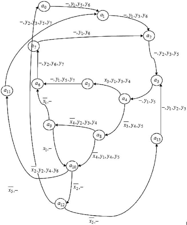
Fig. 2. Transition graph of the digital automaton of the automated integrated firefighting system
Acc or d ing to the ta b le o f fu nctioning of the digital automata graph of AISP T we mak e a na ly ti c al expr ess ions in th e S DNF f o r ou tpu t s ig na ls y 1, y 2, y 3 , and also signals of control of triggers D 4, D 3, D 2 , D 1 . T h e per f ec t d is ju nctive normal form of the function is a disjunct ion of ele me ntar y c o njunctions [7, 15].
The output signal y 1 wi ll be g e ne r a t e d if the a u toma ton is in state a 0 , or in a 1 , or in a 3 , or in a 5 , or in a 7 , or in a 13 , and the sign a 4 x 3 = 1, or in state a 8 and the sign x 4 = 0. Similarly the functions for o ther ou tput sig nals a n d t r i gg e r c ont r o l sig nals ar e wri tten [ 10, 13] .
Table 4
Functioning of the graph of the digital automaton ASPT
|
y 1 = а о v a 1 v a 3 v a 4 x 3 v a 5 v a 7 v a8 x 4 v a 13 |
(1) |
|
y 2 = a 2 v a 6 v a8 x 4 v a 1o x 2 v a 11 v a 13 |
(2) |
|
y 3 = a 1 v a 2 v a 4 x 3 v a 8 x 4 v a11 v a 13 |
(3) |
|
y 4 = a 4 x 3 v a 4 x 3 v a 8 x 4 v a8 x 4 v a 1 o x 2 = a 4 v a 8 v a 1o x 2 |
(4) |
|
y 5 = a o v a 2 v a 3 v a 4 x 3 v a 5 v a 8 x 4 v a 1 1 |
(5) |
|
y 6 = a 0 v a 1 v a6 v a 7 v a 1o x 2 |
(6) |
|
y 7 = a 5 v a 6 v au |
(7) |
|
D 1 = a o v a 2 v a 4 x 3 v a 6 v a 8 x 4 v a 1o x 2 v a 11 v a 12 x5 v a 13 |
(8) |
|
D 2 = a 1 v a 2 v a 5 v a 6 v a 7 v a 8 x 4 v a 9 x 1 v a 9 x 1 v a 10 x 2 v a 13 = = a 1 v a 2 v a 5 v a 6 v a 7 v a8 x 4 v a 9 v a 10 x 2 v a 13 |
(9) |
|
D 3 = a 3 v a 4 x 3 v a 5 v a 6 v a 9 x 1 v a 10 x 2 v a 10 x 2 v a 12 x 5 = = a 3 v a 4 x 3 v a 5 v a 6 v a 9 x 1 v a 10 v a 12 x 5 |
(10) |
|
D 4 = a 4 x 3 v a 8 x 4 v a 8 x 4 v a 9 x 1 v a 10 x 2 v a 10 x 2 v a 12 x 5 = = a 4 x 3 v a 8 v a 9 x 1 v a 10 v a 12 x 5 |
(11) |
Formulas (4), (9), (10), and (11) have been simplified using the gluing law. Using the laws of double negation and de Morgan formulas, the initial expressions from the basis of AND, OR, NOT are converted to the basis of AND, NOT.
|
y 1 = a 0 л a 1 л a 3 л a 4 x 3 л a 5 л a 7 л a 8 x 4 л a 13 |
(12) |
|
y 2 = a 2 л a 6 л a 8 x 4 л a 10 x 2 л a 11 л a 13 |
(13) |
Convert all other formulas by analogy. With the help of the Logic Converter from the MultiSIM simulator program we will minimize the logic functions, which determine each of the control signals of the KS 1 triggers according to Table 4. The results of the minimization of the logic functions are shown in the figu re s (Figs. 3–15) [9].
J 1 = QQQ 2 Q 3 ;
k 1 = Q 2 Q 3 Q 4 + Q 2 Q 3 Q 4 ;
J 2 = QQ 3 + QQ Q 4 ;
K 2 = Q i Q 3 + Q 1 Q 3 Q 4 ;
J 3 = Q + Q 2 ;
K 3 = Q + Q 2 ;
J 4 = Q 1 Q 2 Q 3 Q 4 ;
K 4 = Q 1 Q 2 Q 3 .
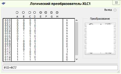
Fig. 3. Minimization of the logic function to control trigger signals K 1
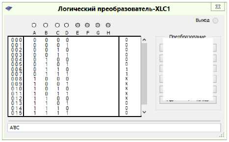
Fig. 4. Minimization of the logic function to control the trigger signals J 1
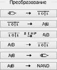
Fig. 5. Minimization of the logic function to control J 2 trigger signals
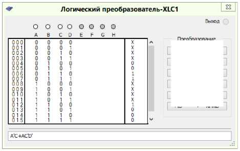
Fig. 6. Minimization of the logic function to control trigger signals K 2
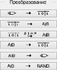
Fig. 7. Minimization of the logic function to control J 3 trigger signals
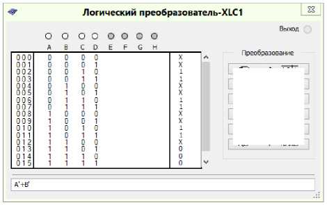
Fig. 8. Minimization of the logic function for the control of trigger signals K 3
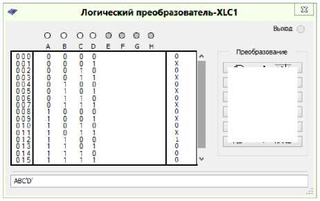
Fig. 9. Minimization of the logic function to control the trigger signals J 4
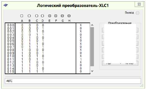
Fig. 10. Minimization of the logical function for the control with the K 4 trigger signals
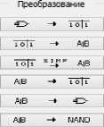
Now let's minimize the logical functions of KS 2, using also Logic Converter from the MultiSIM simulator. The result of minimization of logical functions (Figs. 11–15).
Y 1 = Q i Q 2 Q 3 Q 4 + Q i Q 2 Q 3 Q 4 ;
y 2 = QQ 2 Q 3 Q 4 + Q i Q 2 Q 4 + Q i Q 3 Q 4 ;
Y 3 = QQ 2 Q 4 + Q i Q &;
y 4 = Q i Q 2 Q 3 q 4 + qq 2 Q 4 + Q i Q 2 Q 3 Q 4 + Q 2 Q Q 4 ;
y 5 = Q Q 3 Q 4 + Q 2 Q 3 Q 4 + Q i Q 2 Q 3 Q 4 + Q i Q 2 Q 3 Q 4 .

Логический преобразователь-XLCI
Fig. 11. Minimization of the logic function to control the signals of trigger Y 1
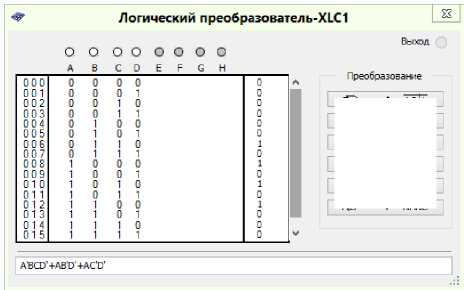
Fig. 12. Minimization of the logic function for the Y 2 trigger signal control
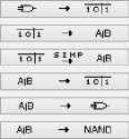
Fig. 13. Minimization of the logic function for the Y 3 trigger signal control
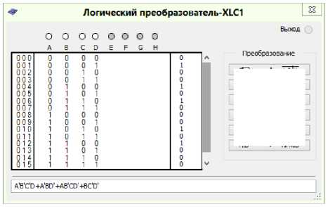
Fig. 14. Minimization of the logic function to control the signals of trigger Y 4
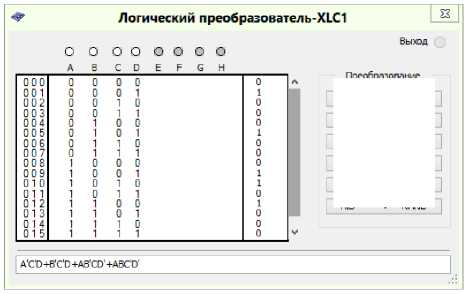
Fig. 15. Minimization of the logic function to control the trigger signals Y 5
Conclusion
Minimized logic functions for KS 1 and KS 2 will be used in the construction of the model of digital automata of automated integrated fire protection system.
To simplify the CA scheme the minimized logic functions for KS 1 and KS 2 are analyzed and the same logic functions are defined. On the basis of the functional diagram of CA its circuit diagram on the selected series of digital integrated circuits is built.
References Conducting a synthesis of a digital automaton for an automated firefighting system
- Topolsky N.G. [Problems and principles of creating integrated security and life support systems]. Proceedings of the Fourth International Conference "Informatization of security systems" - ISB-95. Moscow, VIPTSH MVD RF, 1995, pp. 14-17. (in Russ.)
- Pupkov K.A., Egupov N.D. Metody klassicheskoy i sovremennoy teorii avtomaticheskogo upravleniya [Methods of Classical and Modern Automatic Control Theory]. Moscow, Bauman Moscow State Technical University, 2004.
- Protivpozhara. Entsiklopediya bezopasnosti [Against Fire. Encyclopedia of Security]. Available at: http://protivpozhara.ru/tipologija/teorija/pozhary-i-vzryvy-na-vzryvopozharoopasnyx-obektax.
- Yurevich E.I. Teoriya avtomaticheskogo upravleniya [Theory of automatic control]. St. Petersburg, VCB-Peterburg, 2007.
- Little I.D.C. Models and Managers. The Concept of a Decision Calculus. Management Science, 1970, vol. 16, no. 8.
- Larichev O.I., Petrovsky A.V. [Decision Support Systems. The modern state and prospects for their development]. Progress of science and engineering. Ser. of Technical Cybernetics. Moscow, VINITI, 1987, vol. 21, pp. 131-164. (in Russ.)
- Edwards J.S. Expert Systems in Management and Administration - Are they different from Decision Support Systems? European Journal of Operational Research, 1992, vol. 61, pp. 114-121.
- Topolsky N.G., Tarakanov D.V. [Modeling the dynamics of fire monitoring parameters in the building based on cellular automata]. Security Systems - 2016: Proceedings of the 25th International Scientific and Technical Conference. Moscow, Academy of State Fire Service of the Ministry of Emergency Situations of Russia, 2016, pp. 585-588. (in Russ.)
- Shalyto A. A. [Automated programming]. Computer science and information technology: theses of reports of the International scientific conference in memory of Professor A. M. Bogomolov. Saratov, Saratov State University, 2007. (in Russ.)
- Martinov G.M., Kozak N.V., Nezhmetdinov R.A. Implementation of Control for Peripheral Machine Equipment Based on the External Soft PLC Integrated with CNC. 2017 International Conference on Industrial Engineering, Applications and Manufacturing, ICIEAM 2017, 16-19 May 2017, pp. 1-4.
- Martinova L.I., Kozak N.V., Nezhmetdinov R.A. The Russian multi-functional CNC system AxiOMA control: Practical aspects of application. Automation and remote control, 2015, vol. 76, no. 1, pp. 179-186.
- Martinov G.M., Nezhmetdinov R.A., Kuliev A.U. Approach to implementing hardware-independent automatic control systems of lathes and lathe-milling CNC machines. Russian Aeronautics, 2016, vol. 59, no. 2, pp. 293-296.
- Mori Masahiko, Fujishima Makoto, Yohei Oda. 5 axis mill turn and hybrid machining for advanced application. Procedia CIRP, 2012, vol. 1 (1), pp. 22-27. DOI: 10.1016/j.procir.2012.04.004
- Patent EP 0690426 (A2), G09B 19/00. Système d'entraînement à l'emploi de l'ordinateur, 03.01.1996.
- Patent EP 1111966 A, G08B 5/00. Signaling Device, 27.06.2001.
