Contact algorithm measurement method for current crystals area grown by Czokhralski method

Author: Sahansky S. P., Yulenkov S. E.
Journal: Siberian Aerospace Journal @vestnik-sibsau-en
Section: Technological processes and material science
Article in issue: 4 vol.20, 2019.
Free access
For crystals grown from the liquid melt according to the Czochralski method when monitoring and controlling the current crystal area based on the contact measurement method, the requirements for improving the accuracy of measuring the crystal area on the cylindrical part of the growth are determined. To eliminate errors due to the accuracy of stabilization of the melt level in the crucible, an algorithm for the operation of the crystal growing unit is proposed which is performed by the programm using the control system. The evaluation time of the control signal on the growing crystal cylindrical part is taken as the sampling time of a given number of crucible movement pulses. The calculation of the control signal starts at the time of the melt level sensor closure, the calculation of the control signal ends at the time of the melt level sensor closure as well, provided that a given number of crucible movement pulses is sampled. The control signal evaluation time in the previous control cycle is used in the current cycle to calculate the melt level sensor closing and opening pause. In the control system at the moment of the contact sensor closure a pause of the closed and the same subsequent pause of the open state of the level sensor is held. During pauses, the status of the contact sensor is not analyzed by the control system and the control of the crucible ascent occurs at a slowed down and accelerated rate of the crucible ascent during “conditionally” closed and “conditionally” open states of the level sensor. The control system is permanently reset at the end of each control cycle. The program control system provides the above algorithm for controlling the process of growing crystals from the liquid melt according to the Czohralski method, at the same time the accuracy of determining the current area of the grown crystal is about 1 %.
Growth, crystals, melt level sensor.
Short address: https://sciup.org/148321710
IDR: 148321710 | UDC: 004.07 | DOI: 10.31772/2587-6066-2019-20-4-485-496
Text of the scientific article Contact algorithm measurement method for current crystals area grown by Czokhralski method
Introduction The method for controlling the growing process of a single crystal according to the “Czohralski” method is proposed in the work [1], based on the use of a template simulating a crystal of a given shape as a programmer. The crucible with melt and the container with liquid are placed on the upper cup laboratory scales. In the process of growth the template is immersed in the liquid at the same speed as the crystal is drawn from the melt. The template and crystal are connected by a flexible rod. The equilibrium is maintained if the amount of the solid phase and the liquid displaced by the template per a time unit is the same. In case of imbalance (reduction or increase in the crystal diameter), the error signal of the scales after the optoelectronic converter and amplification is used as a programming one for the heater temperature control with the signal from the thermocouple.
A continuously decreasing level of the melt in the crucible is controlled by a laser meter in the device [2] when drawing a single crystal of a given diameter. The signal from the laser melt level meter is compared with a programmable level change setup unit, and the difference signal after this comparison is used to correct the melt temperature through the heater power regulator and the crystal drawing speed.
Microprocessor control systems for the growth of germanium crystals, developed on the basis of patents [3; 4], were introduced into the semiconductor production of germanium crystals growing (fig. 1), in turn, this development is an analogue of the control systems given in [1; 2].
The work of programmable control systems based on the contact method for measuring the current area of the grown crystals (fig. 1) is as follows: under the control system monitoring, a crystal with d diameter is grown in the chamber with growing rates V з and crystal rotation W з , while the molten metal located in the crucible with an inner diameter D rotates with an angular velocity W т with decreasing melt in the crucible.
The signal from the contact sensor is supplied through the smoothing filter C1, R1, R2 and the computer matching unit to decide on the control of the crucible lifting, which is carried out by means of the step motor control unit.
In addition to the crucible lifting speed V т, the information is generated in the system on the movement of the crucible X итц (with discreteness x т ) and information X изц on the movement of the crystal (with discreteness x т ) using the crucible and seed displacement sensors.
Computer control of the crystal growth rates V з , crystal rotation W з , crucible rotation W т is carried out through appropriate drives. The melt temperature control is carried out on the basis of the formation of the temperature Т з set from the computer to the temperature controller based on the temperature sensor of the heater side surface.
The basic principles of the control system at the contact method of current crystal area measuring. The control of the crystal growth rate V з ( x ), the temperature of the heater side surface T з ( x ), the rotation speed of the crystal W з ( x ) and the crucible W т ( x ) is formed on the basis of expressions (1–4):
-
V , ( x ) = V m ( x ) + Z ■ K , ■ y , (1)
Т з ( x ) = T, , ( x ) + Z ■ A t -J y ■ dx , (2)
W 3 ( x ) = W 3 n ( x ), (3)
W m ( x ) = W mn ( x ), (4)
where K V – the proportional speed regulation coefficient; A T – the integral coefficient of temperature control; V зп ( x ), W зп ( x ), W тп ( x ), T зп ( x ), – program specification of the law of technological parameters change; V з ( x ), W з ( x ), W т (x), T з ( x ) – general control of technological parameters; Z – the sign of control capture by diameter on the cylindrical part of the crystal; x – the displacement along the axis of the crystal; y – the control signal for the deviation of the current area of the grown crystal from the given.
The process of stabilizing the crystal diameter occurs in the control system in accordance with expressions (1)–(2), when the sign of capturing control by diameter ( Z = 1) on the cylindrical part of the crystal is included, based on the control signal y . If we specify the geometry of the grown crystal and its axial gradient in the solid part, then it is possible to pre-simulate the setting of the speed and temperature of growth in all sections of the crystal according to the model [5].
1 7
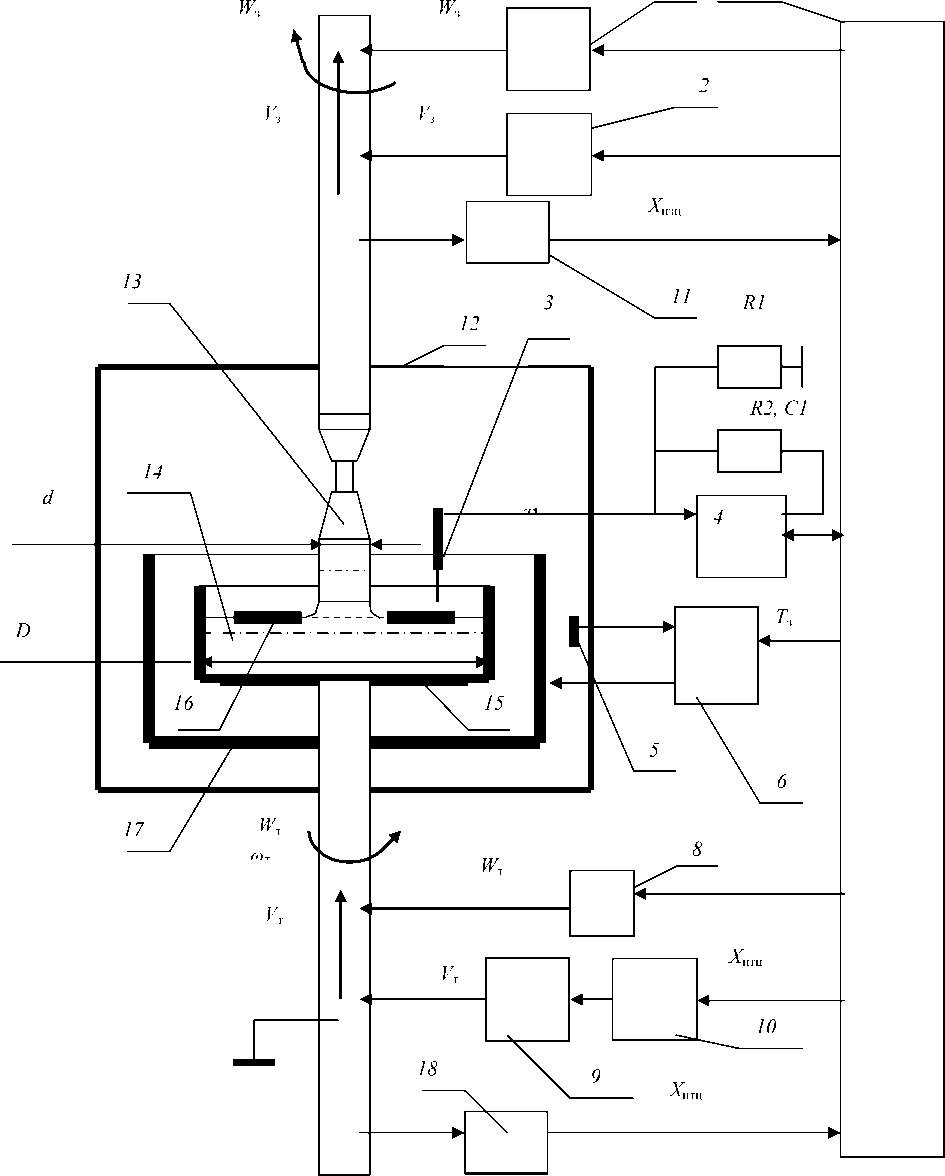
Fig. 1. Control system based on the contact method of measurement:
1 – seed rotation drive; 2 – seed drive; 3 – contact sensor; 4 – coordination unit with a computer; 5 – temperature sensor; 6 – temperature regulator; 7 – the computer; 8 – rotational drive of the crucible; 9 – stepper motor; 10 – stepper motor control unit; 11 – the sensor of seed movement; 12 – the chamber; 13 – ingot; 14 – melt of metal; 15 – crucible;
16 – screen; 17 – heater; 18 – crucible displacement sensor
Рис. 1. Система управления на основе контактного метода измерения:
-
1 – привод вращения затравки; 2 – привод перемещения затравки; 3 – контактный датчик; 4 – блок согласования с ЭВМ; 5 – датчик температуры; 6 – регулятор температуры; 7 – ЭВМ; 8 – привод вращения тигля; 9 – шаговый двигатель; 10 – блок управления шаговым двигателем; 11 – датчик перемещения затравки; 12 – камера;
13 – слиток; 14 – расплав металла; 15 – тигель; 16 – экран; 17 – нагреватель; 18 – датчик перемещения тигля
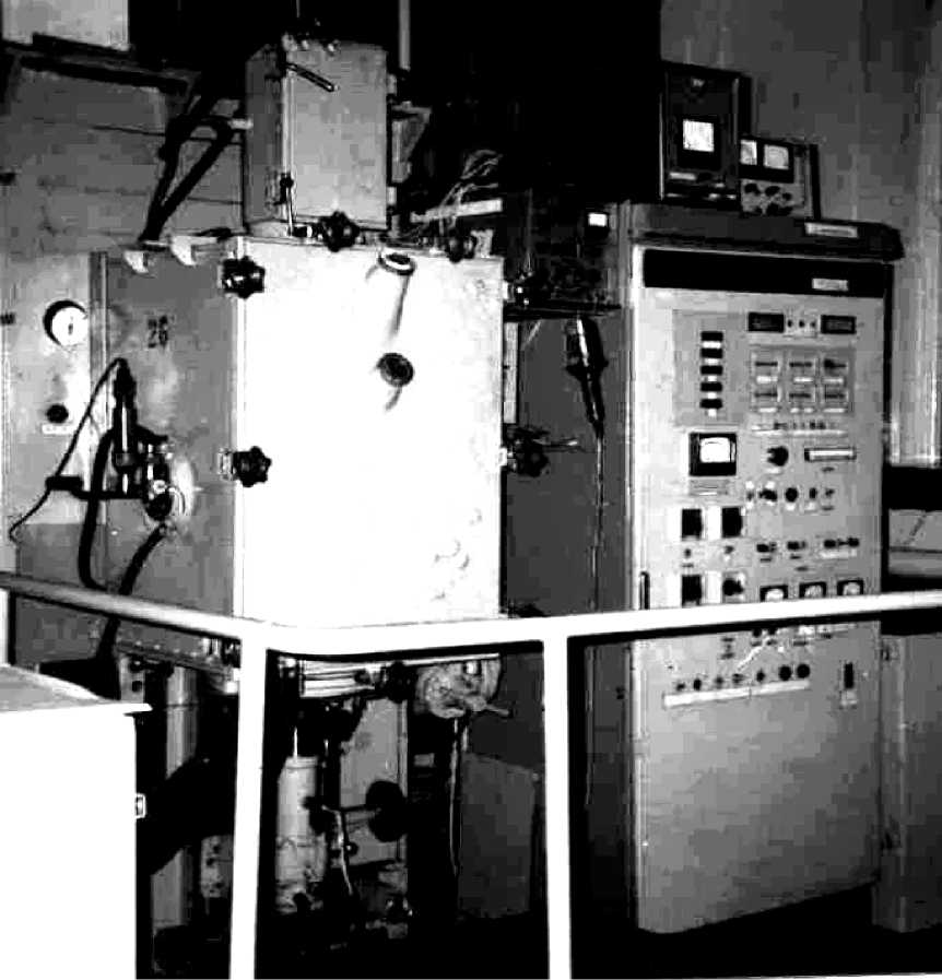
Fig. 2. Microprocessor control system for drawing germanium single crystals
Рис. 2. Микропроцессорная система управления вытягиванием монокристаллов германия
The design of the programmable automatic control system for germanium crystal drawing is shown in fig. 2–4 show a view of a floating graphite screen with a melt level sensor and a view of a grown crystalline germanium billet with a diameter of 104 mm.
The basis for the contact method for crystal growth control and management on the cylindrical part [6–15] is the current area management (or diameter when round) of the growing crystal according to the control signal y , calculated as a function of the deviation of the current crystal area from the given one, using crystal X зц and crucible X тц displacements for the period T ц of the control signal y estimate.
The shape of the grown crystal directly depends on the accuracy of determining the control signal y and the absence of significant interference in the calculated value.
The speed of the melt decrease in the crucible V р , as well as the accelerated speed of the crucible lifting V тм after opening the contact sensor and the slowed lifting speed of the crucible after closing the contact sensor V тм / M are determined by the expressions (5–9), in which the speed increase coefficients (C = 4) and the crucible lifting speed decrease (M = 4), which has has been applied in growing the cylindrical part of the crystal and provides periodic closure and opening of the contact sensor in the range of melt level change of about 1–2 μm.
When growing the crystal forward and reverse cones, the condition for the complete stop of the crucible rise, when the melt level sensor is closed ( M = ∞), is used to control the speed of the crucible moving upward.
V = v ■ Ь-рз
р
ж
d 1 2
D
у у у . ттмр
d max d
= V3 •р-Рж
•
d max D
d max
= d • . ,
1 V1 - 1/ c
у
V = V м = V • т M р
d min d
d min d max
= V3 •-Рт- • Рж
, M
d min D
,
where V т – the crucible lifting speed; V р – the speed of the melt decrease in the crucible; V з – the crystal growth speed; d – the current crystal diameter; D – the inner diameter of the crucible; р т - the specific density of solid material; р ж - the specific density of liquid material; d 1 – the specified diameter of the grown crystal on the cylindrical part; d max – the maximum permissible diameter of the grown crystal, with which compliance the main condition under which the sensor and screen close after opening is fulfilled; d min – the minimum permissible value of the crystal diameter at which the condition of the screen lagging behind the sensor after its closed state is observed.
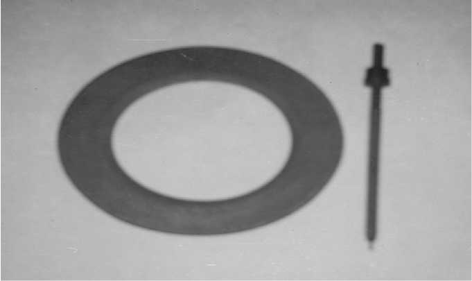
Fig. 3. Floating graphite screen and melt level sensor
Рис. 3. Плавающий графитовый экран и датчик уровня расплава
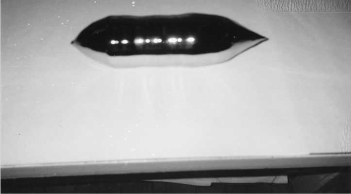
Fig. 4. A germanium billet with a diameter of 104 mm
Рис. 4. Слиток германия диаметром 104 мм
For the contact measurement method the control signal y , the movement value of the seed X зц and the crucible X тц during the evaluation time T ц can be represented in the form of expressions (10–14):
Ky итц A • B
X изц
A ,
Kу = в •
Х, •Рж тж
•
x з •Р т
D
d _
,
изц
^ =—
d
d 1
1 ,
The total movement time t in the process of closing the contact sensor with a slowed down speed and the total movement time with the accelerated speed of the crucible after opening the sensor t д , as well as the number of cycles K ц for closing and opening the sensor during the evaluation period of the control signal T ц can be represented in the form of expressions (19–20):
t д ( d ) = t •


- 1
X зц = X изц • x з , (13)
т
ц ц (tд +1),
X тц = X итц • x т , (14)
where t - the time of the crucible movement with a
where А , В - scaling coefficients; K у – the setting of a given diameter (area) of the grown crystal; X изц – the seed movement with the reference discreteness x з ; X итц – the crucible movement with reference discreteness x т ; x з – the reference discreteness of the seed movement; x т – the reference discreteness of the crucible movement.
Expression (12) shows the direct relationship of the control signal y with the deviation of the current crystal area from the given one.
During the evaluation cycle T ц , the control signal y is calculated in the control system by expression (10), and using the recording in the control system the settings of the diameter K у , on the cylindrical part of the grown crystal, the growing area is set.
An open step drive with a stepper motor is used as a crucible lifting drive for upward lifting speed control, providing a process of repeatedly changing crucible lifting speed according to the signal from the contact level
sensor.
The expressions for the movement pulses of the seed X изц , crucible X итц and time T ц of the control signal estimate y can be represented in the form of expressions (15–16):
X_ „• K итц y
X изц = в ,
slowed-down speed V тм / M after the sensor is closed during the evaluation period of the control signal; t д , – the time of the crucible movement with an accelerated speed V тм after opening the sensor during the evaluation period of the control signal; K ц – the number of cycles of closing and opening the sensor during the time T ц .
The accuracy of the contact method for measuring the current area of the grown crystal. In the control system of the germanium drawing unit under consideration, a timing control diagram was applied (fig. 5) when growing the cylindrical part of the crystal, which means that at the moment of contact sensor closure in the control system it is necessary to withstand a program pause τ of the closed and the subsequent pause τ of the open state of the level sensor.
At pauses of τ, the state of the contact sensor is not analyzed by the control system and the crucible lift control is performed with the slow and accelerated crucible lifting speed at the moments of “conditionally” closed and “conditionally” open states of the level sensor.
After holding two pauses, the conditions of the closure of the melt level sensor are analyzed and the drive for moving the crucible up is controlled.
This control increases the noise immunity of the method of calculating the current area on the cylindrical part of the grown crystal due to the lack of system response to the operation of the contact sensor during two
pauses.
т _ Xизц • xз _ Xзц _ Xитц • K у • xз ц у V BV ’ зз з
where T ц - control signal evaluation period (working time of a given number of pulses X итц or X изц ).
Let us take as the evaluation time T ц of the control signal y on the cylindrical part of the grown crystal the sample time of the specified number of pulses movement of the crucible X тц (in the process of melt decrease in the crucible) in accordance with expressions (17–18):
The opening value of the melt level on the cylindrical part of the grown crystal L p is set within 1 μm. The pause time τ and the t дм ( d ) time of the sensor closure (after two pauses) can be represented in the form of expressions
(21–22) provided that the melt sensor is opened by the
value L p:
т
ц
тц
|
X зц • |
Р т -------------• Р ж |
d 1 _ D |
||
|
X тц |
" D |
1 |
2 |
|
|
V з |
_ d 1 |
. |
, |
|
,
X тц •
t дм( d ) = T^


-T ,
where т - the crucible movement time with a slow speed V гм / M after the sensor closes (when the melt decreases by L p ); t дм ( d ) – the crucible movement time with accelerated speed V тм after two pauses are held τ until the sensor closes.
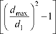
The error r in the calculation of the control signal, depending on the accuracy of stabilization of the melt level in the crucible, can be represented in the form of expression (23), which is graphically presented in fig. 6:
x -Рж . D xз -Рг L d 1
where r - an error in the calculation of the control signal for the measurement cycle; x – the accuracy of stabilization of the melt level in the crucible.
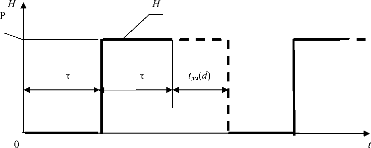
Fig. 5. Timing diagram of the level sensor:
H - operation of the contact level sensor ( P - sensor open)
Рис. 5. Временная диаграмма работы датчика уровня:
H - работа контактного датчика уровня ( Р - датчик разомкнут)
r
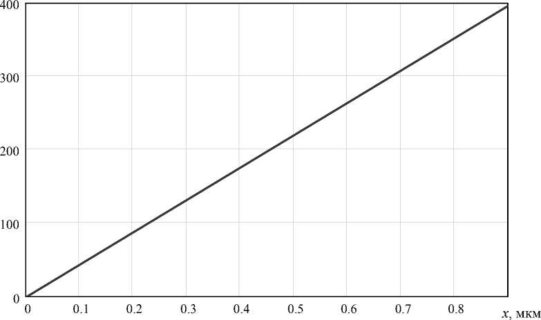
Fig. 6. The error of the control signal r, depending on the accuracy of stabilization of the melt level in the crucible x with: x з = 0,0216 μm; d 1 = 100 mm; D = 300 mm; A = 1;
Р т = 5,35 g/cm2; р ж = 5,57 g/cm2
Рис. 6. Погрешность сигнала управления r в зависимости от точности стабилизации уровня расплава в тигле x при: x з = 0,0216 мкм; d 1 = 100 мм;
D = 300 мм; A = 1; р т = 5,35 г/см2; р ж = 5,57 г/см2
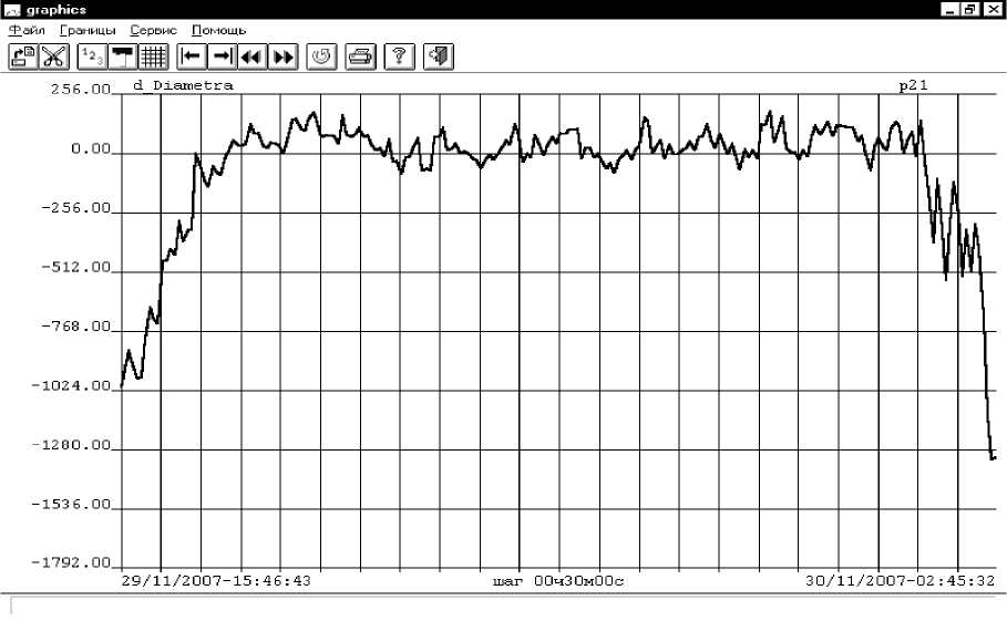
Fig. 7. Control signal change graph y (d_Diametra)
Рис. 7. График изменения сигнала управления y (d_Diametra)
The time dependence of the control signal y during an industrial installation operation is shown in fig. 7.
The algorithm for improving the accuracy of the contact method for measuring the current area of crystals. During the evaluation of the control signal y on the cylindrical part of the grown crystal, the sampling time of a given number of X итцу crucible movement pulses is taken from expression (24) with a sampling discreteness reference x т , which corresponds to the evaluation time of the control signal T цу in accordance with expression (25). These parameters are calculated in each previous control cycle.
X итцу = _ зц -^ -Г d 1 1 ■ -, (24)
Рж D хт жт
T = _итцу ■ D ■ x (25) цу V з |_ d I ] т.
To eliminate the error due to the stabilization accuracy of the melt level in crucible r , the following program algorithm for the control system operation is proposed:
-
1. During the evaluation of the control signal y on the grown crystal cylindrical part, the sampling time for a given number of pulses of the crucible X итцу movement is taken according to expression (24) with discreteness reference x т and the estimation time Т цу according to expression (25).
-
2. The calculation of control signal y starts at the moment of the melt sensor closure, provided that a speci-
- fied number of crucible Xитцу movement pulses is sampled.
-
3. The calculation of the control signal y ends at the moment of the melt sensor closure, provided that the specified number of pulses of movement of the crucible X итцу movement is sampled.
-
4. The Т цу evaluation time of the set number of pulses of the crucible X итцу movement in the previous control cycle is used in the current cycle to calculate the pause τ of closure and conditional opening of the melt level sensor according to the expressions (16, 21).
In each control cycle, the stabilization error of the melt level in crucible r is minimized due to its reset during the control cycle start (closure) of the melt level sensor.
The block diagram of the program of the above stated algorithm is shown in fig. 8–11 for diameters d 1= 80 mm; d 1=100 mm; d 1 = 120 mm; and X тц = 68 μm; X тц = 107 μm; X тц = 154 μm, respectively (at a given value of the melt level opening L p = 1 μm), an example of calculating the control signal y is given.
Conclusion. For crystals grown from the liquid melt according to the Czochralski method, when monitoring the current crystal area based on the contact method for measuring the current crystal area, the requirements are identified to improve the accuracy of measuring the current crystal area on the cylindrical part of the grown crystal.
To eliminate the error due to the accuracy of stabilization of the melt level in the crucible, a program algorithm for the operation of the crystal growing unit is proposed, in which the time of the control signal y evaluation on the cylindrical part of the grown crystal is taken as the sampling time of a given number of Xитцу crucible movement pulses. The calculation of the evaluation time of the control signal y at the moment of closure of the melt sensor starts, the calculation of the control signal y at the moment of closure of the melt sensor ends, provided that the specified number of crucible Xитцу movement pulses is sampled.
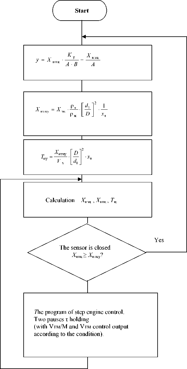
Fig. 8. Block diagram of the program
Рис. 8. Блок-схема программы
y
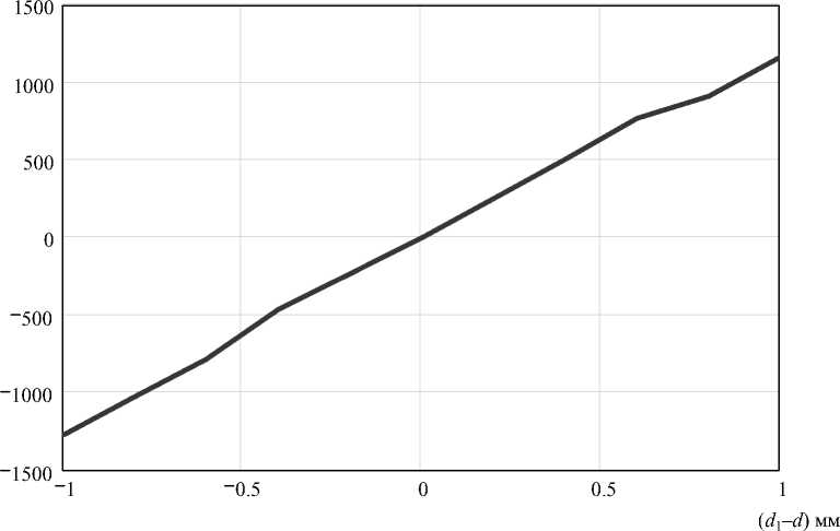
Fig. 9. Schedule of change of control signal y from ( d 1 – d ) at: ρ т = 5.35 g/cm 2 ; ρ ж = 5.57 g/cm 2 x т = 0.0266 μm; x з = 0.0216 μm; d 1 = 80 mm; D = 300 mm; M = 4; C = 4; B = 16; V з = 0.00833 mm/s;
X зц = 1000 μm; X тц = 68 μm; T ц =120 s; L p = 1 μm
Рис. 9. График изменения сигнала управления y от ( d 1 – d ) при: ρ т = 5,35 г/см 2 ; ρ ж = 5,57 г/см 2: ; x т = 0,0266 мкм; x з = 0,0216 мкм; d 1 = 80 мм; D = 300 мм; M = 4; C = 4; B = 16;
V з = 0,00833 мм/с; X зц = 1000 мкм; X тц = 68 мкм; T ц = 120 с; L p= 1 мкм
y
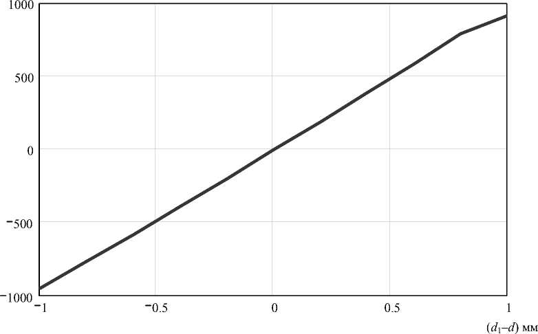
Fig. 10. Schedule of change of control signal y from ( d 1 – d ) at: ρ т = 5.35 g/cm 2 ; ρ ж = 5.57 g/cm 2 x т = 0.0266 μm; x з = 0.0216 μm; d 1 = 100 mm; D = 300 mm; M = 4; C = 4; B = 16; V з = 0.00833 mm/s; X зц = 1000 μm; X тц = 107 μm; T ц =120 s; L p = 1 μm
Рис. 10. График изменения сигнала управления y от ( d 1 – d ) при: ρ т = 5,35 г/см 2 ; ρ ж = 5,57 г/см 2: ; x т = 0,0266 мкм; x з = 0,0216 мкм; d 1 = 100 мм; D = 300 мм; M = 4; C = 4; B = 16;
V з = 0,00833 мм/с; X зц = 1000 мкм; X тц = 107 мкм; T ц = 120 с; L p = 1 мкм
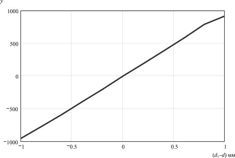
Fig. 11. Schedule of change of control signal y from ( d 1 – d ) at: ρ т = 5.35 g/cm 2 ; ρ ж = 5.57 g/cm 2 x т = 0.0266 μm; x з = 0.0216 μm; d 1 = 120 mm; D = 300 mm; M = 4; C = 4; B = 16; V з = 0.00833 mm/s;
X зц = 1000 μm; X тц = 154 μm; T ц = 120 s; L p = 1 μm
Рис. 11. График изменения сигнала управления y от ( d 1 – d ) при: ρ т = 5,35 г/см 2 ; ρ ж = 5,57 г/см2:; x т = 0,0266 мкм; x з = 0,0216 мкм; d 1 = 120 мм; D = 300 мм; M = 4; C = 4; B = 16;
V з = 0,00833 мм/с; X зц = 1000 мкм; X тц = 154 мкм; T ц = 120 с; L p = 1 мкм
The evaluation time Т цу of the control signal y in the previous control cycle is used in the current cycle to calculate the melt level sensor closing and opening pause. In the control system, at the moment the contact sensor closure, a pause of the closed and the same pause of the subsequent open state of the level sensor is held.
At pauses, the state of the contact sensor is not analyzed by the control system and the control of the crucible lift occurs with a slow and accelerated crucible lifting speed at “conditionally” closed and “conditionally” open states of the level sensor.
The control system is reset at each moment of the control cycle completion, provided that the melt level sensor is closed.
All this ensures the accuracy of determining the current area of the grown crystal of about 1% on the cylindrical part of the grown crystal in the automatic control system.
References Contact algorithm measurement method for current crystals area grown by Czokhralski method
- Schmidt F., Voszka R. Phantom controlled automatic Czochralski growth appparatuss. Crystal Research and Technology. 1981, Vol. 10, No. 11, P. 127–128.
- Pat. 2337169. Federal Republic of Germany, ICI В01 J17/18-1974.
- Sahansky S. P., Podkopaev O. I., Petrik V. F. Sposob upravleniya protsessom vyrashchivaniya monokristallov germaniya iz rasplava i ustroystvo dlya ego osushchestvleniya [A method for controlling the process of growing single crystals of germanium from the melt, and a device for its implementation]. Patent RF, no. 2128250, 1997.
- Sahansky S. P., Podkopaev O. I., Petrik V. F., Laptenok V. D. Sposob upravleniya protsessom vyrashchivaniya monokristallov germaniya iz rasplava i ustroystvo dlya ego osushchestvleniya [A method for controlling the process of growing single crystals of germanium from the melt, and a device for its implementation]. Patent RF, no. 2184803, 1999.
- Sakhanskiy S. P. [Controlling the shape of semiconductor crystals when grown according to the Czochralski method]. J. Sib. Fed. Univ. Eng., Technol. 2014, Vol. 7, No. 1, P. 20–31.
- Sakhanskiy S. P. [Basic mathematical relationships of the contact method for controlling the growth of single crystals by the Czochralski method]. Vestnik SibGAU. 2005, No. 7, P. 85–88 (In Russ.).
- Sakhanskiy S. P. [Determination of the correction value of the control signal by diameter, from the change in the height of the column of the meniscus of the crystal, with the contact method for controlling the growth of single crystals by the Czochralski method]. Vestnik SibGAU. 2005, No. 7, P. 89–90 (In Russ.).
- Sakhanskiy S. P. [Determination of the magnitude of the melt fluctuation and sensitivity with a contact method for controlling the growth of single crystals by the Czochralski method]. Vestnik SibGAU. 2005, Vol. 1, No. 8, P. 103–104 (In Russ.).
- Sakhanskiy S. P. [The error in the contact method for measuring the current area of the grown germaniumsingle crystal]. Pribory i sistemy. Upravlenie. Kontrol'. Diagnostika. 2009, No. 2, P. 43–46 (In Russ.).
- Sakhanskiy S. P. [Measurement of the area of a single crystal in the system for automatic control of germanium germination.]. Mekhatronika. Avtomatizatsiya. Upravlenie. 2008, No. 8, P. 44–48 (In Russ.).
- Sakhanskiy S. P. [Plant for growing germanium single crystals on the basis of the contact method of measurement]. Bulletin of the Samara State University. acad. S. P. Korolev. 2008, Iss. 2, P. 100–105 (In Russ.).
- Sakhanskiy S. P. [Measurement and control of the crystal area on a germanium stretch unit]. Vestnik SibGAU. 2008, Vol. 1, No. 18, P. 148–150 (In Russ.).
- Sakhanskiy S. P. Upravlenie protsessom vyrashchivaniya monokristallov germaniya: monografiya. [Management process of growing single crystals of germanium: monograph]. Krasnoyarsk, SibGAU Publ., 2008, 104 p.
- Sakhanskiy S. P. [Measurement of the area of crystals grown from a liquid melt by the Czochralski method, based on the control of the conditions for closing the contact melt level sensor]. J. Sib. Fed. Univ. Eng., Technol. 2015, Vol. 7, No. 8, P. 835–850.
- Sakhanskiy S. P., Yulenkov S. E. [Improving the accuracy of the contact method for measuring the current area of crystals grown by the Czochralski method]. Siberian Journal of Science and Technology. 2018, Vol. 19, No. 3, P. 550–561.
