Control of nonlinear dynamics of electromechanical systems

Author: Kodkin V.L., Anikin A.S., Baldenkov A.A.
Section: Управление в технических системах
Article in issue: 3 т.19, 2019.
Free access
This article proposes to analyze the processes in the most widely used at present frequency-controlled AC drives, as in automatic control systems with dynamic non-linearities, and structural correction methods, improving their dynamics. For the first time, dynamic formulas of transfer functions of a torque driver in an asynchronous motor with frequency control, taking into account the slip and frequency of the stator voltage, are proposed. Methods for constructing families of frequency characteristics of such electromechanical systems with “frozen” but different values of the frequency of the stator voltage and slip is described. In the Simulink application of the MATLAB software environment, families of frequency characteristics were constructed corresponding to nonlinear transfer functions. The nonlinear transfer functions obtained in this work made it possible to substantiate the structural solutions of linearizing frequency-controlled electric drives and, significantly, increasing their efficiency. Such a solution turned out to be a positive feedback on the current value of the stator current with a dynamic link. This dynamic link ensures the effective action of a positive connection without disturbing the stability of electromechanical systems. The experiments fully confirmed the correctness of the mathematical expressions obtained for nonlinear links of systems and their correction. This paper is an example of how the initial complicated (but more accurate!) Interpretation of nonlinearity allowed us to find a new best solution to the problem of controlling a complex dynamic object.
Ac drive, mathematical analysis, dynamic nonlinearity, frequency response, dynamic correction, positive feedback
Short address: https://sciup.org/147232267
IDR: 147232267 | UDC: 62-83-52 | DOI: 10.14529/ctcr190304
Управление нелинейной динамикой электромеханических систем
Предлагается анализировать процессы в наиболее широко применяемых в настоящее время частотно-регулируемых электроприводах переменного тока, как в системах автоматического регулирования с динамическими нелинейностями, и структурные методы коррекции, совершенствующие их динамику. Впервые предложены динамические формулы передаточных функций формирователя вращающего момента в асинхронном электродвигателе с частотным управлением, учитывающие скольжение и частоту статорного напряжения. Изложены методы построения семейств частотных характеристик таких электромеханических систем при «замороженных», но различных значениях частоты статорного напряжения и скольжения. В приложении Simulink программной среды MATLAB построены семейства частотных характеристик, соответствующие нелинейным передаточным функциям. Полученные в работе нелинейные передаточные функции позволили обосновать структурные решения, линеаризующие частотно-регулируемые электроприводы и существенно повышающие их эффективность. Таким решением оказалась положительная обратная связь по действующему значению тока статора с динамическим звеном. Именно это динамическое звено обеспечивает эффективное действие положительной связи без нарушения устойчивости электромеханических систем. Эксперименты полностью подтвердили правильность полученных математических выражений для нелинейных звеньев систем и их коррекции. Данная работа является примером того, как исходная усложненная (но более точная!) интерпретация нелинейности позволила найти новое лучшее решение задачи управления сложным динамическим объектом.
Text of the scientific article Control of nonlinear dynamics of electromechanical systems
The widespread use of frequency converters for controlling asynchronous motors in recent years has created the impression that there are no problems in the field of automated electric drive (AED). However, attempts to study in depth the dynamic characteristics of such electric drives make it necessary to return to the study of the problems of control of nonlinear systems. Frequency controlled AEDs are a highly non-linear system. The “main” parameter determining the non-linearity of these systems is the variable frequency of the supply voltage. Unlike the stationary non-linearities of the regulatory systems considered in the 80s and 90s of the 20th century, the variable frequency in the AED changes its frequency response.
Variable frequency, strictly speaking, does not allow the use of a mathematical apparatus designed for AC drives, based on vector analysis, since the vector representation of variables over time implies the constancy of the frequency of the supply voltage, or the frequency of rotation of these vectors. However, due to the absence of another, vector methods are used in most research or educational works on AC drives, despite the fact that the authors quite often recognize the illegality of such an approach.
Problem statement
The most effective engineering method for assessing the dynamics of electric drives is the method of frequency analysis. Direct application of this method to asynchronous electric drives is hampered by the presence of significant non-linearities in them. The construction of the frequency characteristics of such systems involves a number of inevitable assumptions. After considering the different versions of these assumptions, the calculation of the dynamic mechanical characteristic set forth in the Usoltsev’s monograph [1] turned out to be the most acceptable. The calculation a repelled by equation 1.36 on p. 23 [1].
It establishes a connection between the current moment ( m ) and slip (β) at the nominal frequency
ω 1nom :
_______ 2Mk _______
(1+T2‘p)[^(l+T2 Р)]+^, where Т2. = ^ - the transient time constant of the rotor, в = ~ — the relative slip, Mk — the critical moment, Sk – the critical slip at the nominal frequency ω1nom.
At the beginning of the working characteristic (for М ≈ 0, β ≥ 0), the transfer function is simplified and reduces to a dynamic link of the 1st order:
m = 2М к = 2М к Р = 2M k (^ i -w)
(1 + T 2 ‘p) ^k (1+T 2 ‘P)S k (1+T 2 ‘P)S k ^ l
At the same time, the transfer function linking the absolute slip and the torque developed by the motor will look as follows:
^ d (p) = £ = "* ш . (2)
АШ (1+7' 2 p)5 k ^ i
However, the results of experiments given in [2–6, 12, 14] showed that it is incorrect to extend this formula to all operating modes.
Solution
Equation (1) allowed us to propose another variant of linearization, in which the initial equation takes the form:
m [(Т2‘)2p2 + 2Т2p + 1 + (£)2] = ^ в(1 + Тp). (3)
Then, the equation connecting moment ( m ), relative slip (в) and engine parameters (Т ’2 - transition time constant; M k , S k – critical moment and critical slip, depending on the frequency ω 1 ) takes the form:
m = 2M k (T 2 p + 1)S k £
(1+7 2 ‘P) 2 s 2 +p2"
and the transfer function linking the absolute slip and moment will take the form:
= 2M k (T 2 P+1)s k
^(p) Wi[(1+T2 ‘P)2sk + p2], where ω1 – the frequency of the stator voltage.
The block diagram of the drive in the working area will take the form shown in Fig. 1.
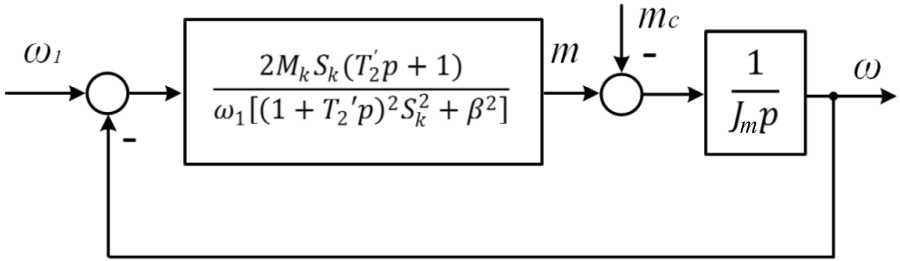
Fig. 1. Structural diagram of an asynchronous motor in the working area
The transfer function of the torque driver changes as the stator voltage and slip frequency varies, i.e. is essentially nonlinear.
It should be noted that at β = 0, the transfer function, as well as the structural diagram, exactly coincide with the linear transfer function and structural diagram for the asynchronous drive, given in the Usoltsev’s monograph [1]. In the proposed non-linear interpretation, the formula and block diagram explain some of the problems of an asynchronous electric drive. To this end, it is proposed to consider the transfer functions and the corresponding frequency characteristics at “frozen”, but different values of the stator voltage frequency and slip. Moreover, instead of the traditional characteristics of the control object, it will be necessary to consider “families”, grouped by varying stator voltage (its frequency) or slip [7].
B e l ow , t he f r eque n c y c ha r acteristics of an asynchronous electric drive with fre qu e nc y c ont r ol bas e d on low-power squirrel cage indu c t ion motor a re show n in F igs. 2 and 3. They are built in the Simulink appl ic ati on of th e MA T LA B sof tw a r e [ 8 –11].
Amplitu de a nd ph a se f r e q u ency characteristics of the motor at a stator volta g e f re que nc y of 10 Hz and s lip c orr e s pond ing to l ow ( 0. 2 M n ) and nominal loads as shown in Fig. 2. Fig. 3 shows similar chara cte ris ti c s f or a st a to r v olt ag e f r e quenc y of 50 Hz.
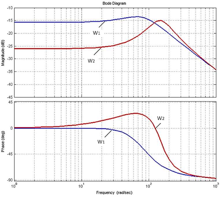
Fig. 2. Frequency responses of an electric motor at a stator voltage frequency of 10 Hz and slip, corresponding to low ( W 1 ) and nominal ( W 2 ) loads
The g iven fr e qu e nc y r espo nses well explain some problems of AC drive. When oper ating at low fr e q ue ncies of th e s tator volt a g e , the phase shifts significantly change with chang ing loa d (a nd sl ip) , whi c h le ads to ins ta b i li ty a nd in e ff icient oper a t ion at low speeds (Fig. 2). Comparison of frequency res ponses at fr e qu e ncie s of s ta t or voltage of 10 and 50 Hz shows that in the range f r om 10 t o 1 00 ra d/ s t he pha s e shi f t s of f re que n c y r e sponses ha v e si gni f i c antly diff e re nt v a lues – from 25 to –45 electric deg re e . T h is me a ns that duri ng a c c eleration and deceleration, the phase shifts cha ng e in suc h a wa y th at a sy ste m with a st a bi li ty m a r g in at a frequency of 50 Hz can become unstable. The f re que n c y of the s tat or v olt a g e will be 10 Hz. T h is ma y be the r e a s on for the different oscillation of the drive at different fr e q ue ncies o f t he st a to r v olta g e, which were noted in [7]. Thus, the nonlinearities of th e tra ns f er f unct ion s of th e l ink of the to r que generator (Fig. 1) require linearization to inc re a se the e ff iciency of t he elec t r ic driv e a nd t he s ame be ha v ior a t di f f er e n t fr eque ncie s
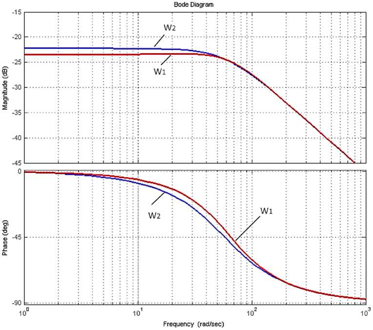
Fig. 3. Frequency responses of an electric motor at a stator voltage frequency of 50 Hz and slip, corresponding to low ( W 1 ) and nominal ( W 2 ) loads
One of the widely use d me thods of li ne ar iza t ion a re v a r io us ty pe s o f so -called “Transvector” con t r o l. W i th th is c on trol, dy na mic links reverse to the dynamic links of the motor are f or me d in the c o ntro l d e vi c e , wh ic h ar e a da p te d t o di f fe r ent mode s of oper ation. Since ideal adaptation is impossible in a real d r iv e , the t r a ns f er functio n s in c orp orated in the software of frequency converters and r ea l a sy nc hron ous mot or s c a n v a r y f or a n um be r o f r easons: a number of parameters are difficult to me a sur e ; t he s tr u cture o f a r e al e l e ctric motor is muc h more complicated than a model; some parameters ma y c ha ng e dur ing o pe r ati on. Dy na mic l ink s a r e qui t e complicated, because the equivalent transfer f unct ions of the frequency converter – as ync hronous motor c a n c o ntain resonant links in some modes. These links lead to control failures, to high- fr e que nc y harmonics, and to differences in dynamics at di ff e re nt spee ds, wh ich wer e ob se r v e d du r i ng the expe rime nts [ 1 ] .
Other options for linearizing a tor que driv e r a re o f in ter e s t [ 7, 14, 15].
C onsid e r the opt ion of a p ply i ng local feedback on the electromagnetic mom e nt in th is st r ucture . The st r uctu r a l dia g r a m is s h own in Fig . 4.
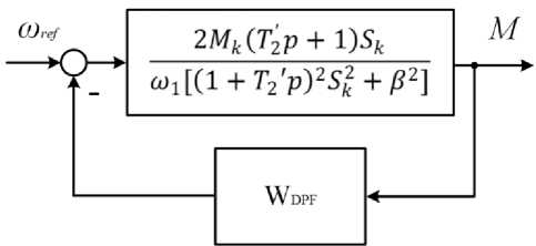
Fig. 4. Block diagram of AED with local feedback on electromagnetic moment
In this case, the transfer function of the torque driver will take the form:
2Mk(T2p+l)sk
W _ toi[(l + T2‘p)2s2. + P2] _ ______________2MkSk(T22p + 1)______________ e4v i+2MkSk(T2P+l)wDPF toi[(1+T2,p)2Sk+P2] + 2Mk5k(T2 p + 1)^DPF
«l[(l+T2‘p)2sk+₽2]
Under the following condition:
Wip2 _-2Mk5k(r;p + 1)Wdpf, that is, if the corrective element will have the following transfer function:
W DPF = - 2M k ^i(h) , (6)
then the transfer function of the torque driver takes the form:
w _ 2MkSk(T2, p + 1) _ 2Mk e4v Wl[(1+T2'p)2sk] WlSk(1 + T2'P), that is, it becomes a linear link, independent of slip (load), and completely coinciding with the transfer function (2), given in the Usoltsev’s monograph [1] for small loads. Pay attention to the formula (8). The dynamic link is a first-order inertia with a coefficient that ultimately depends on the frequency of the stator voltage and on the absolute slip. The sign (–) in front of the formula means that the feedback must be positive. Let's call this connection – dynamic positive feedback (DPF+). It should be noted that the correction of the coefficient of frequency is very easy to implement in frequency converters. Thus, the proposed positive feedback, selected by condition (6), makes it possible to compensate for the external load and the nonlinearity of the asynchronous electric drive, spreading the transfer function of the motor as a 1st order link for any β values. In addition, the block diagram (Fig. 1) and the transfer function of the moment drive link (5) connecting the moment and slip allow us to offer an estimate of the efficiency of the moment drive algorithm: the algorithm that generates the necessary moment with the smallest absolute slip will be more effective [12–15].
Next, we consider the correction of the asynchronous electric drive with the parameters corresponding to the frequencies of the supply voltage (FSV) of 10 and 50 Hz. The initial frequency responses are shown in Fig. 2 and 3. The transfer functions of the initial AED with such parameters and the transfer functions of the corrective links are presented in Table 1. The frequency characteristics of the initial and adjusted AED are shown in Figs. 2, 5 and 6 for the supply voltage frequency of 10 and 50 Hz, respectively.
Table 1
The transfer functions of the torque driver of the initial AED and the corrective element
|
FSV |
* |
WAED(p) |
WPFB |
|
10 Hz |
P 1 |
0,038p + 0,226 |
0,707 |
|
0,0002p 2 + 0,0229p + 1,38 |
0,0038p + 0,226 |
||
|
в 2 |
0,038p + 0,226 |
3,84 |
|
|
0,0002p 2 + 0,0229p + 4,52 |
0,0038p + 0,226 |
||
|
50 Hz |
P 1 |
0,027p + 1,548 |
0,141 |
|
0,006p 2 + 0,628p + 20,56 |
0,27p + 1,548 |
||
|
в 2 |
0,027p + 1,548 |
0,77 |
|
|
0,006p 2 + 0,628p + 21,19 |
0,27p + 1,548 |
*в1 - corresponds to slip at low load, в2 - corresponds to slip at rated load.
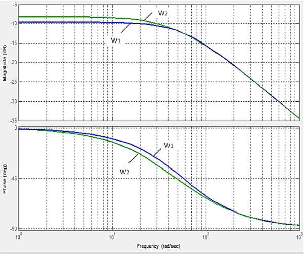
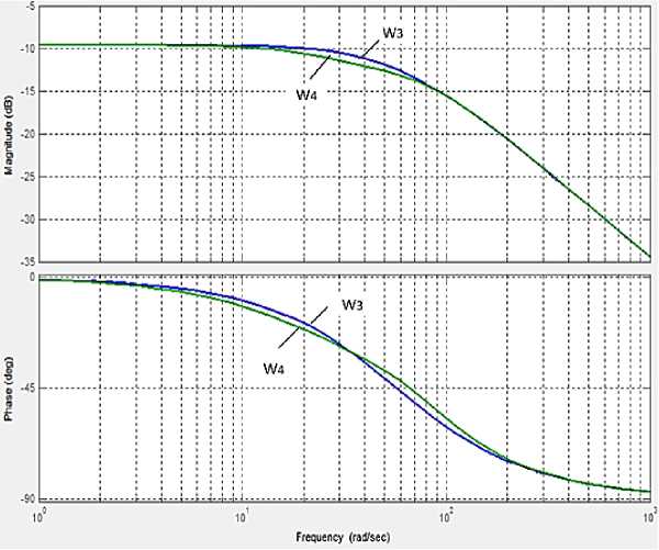
As expected, the frequency responses of the AED with the structural correction proposed in the work are close to the frequency responses of the 1st order linear link.
In widely used AEDs, it is very difficult to realize the link by mechanical moment. Given that the moment is equal to I 1 ·Ψ 2 and in almost all calculations it is assumed that the rotor flux linkage is constant, you can replace the original signal in this local connection with the effective value of the stator current, or its active component, which is calculated in all frequency converters.
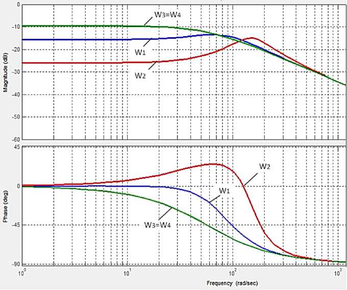
Fig. 5. Frequency responses of the torque driver link: initial ( W 1 , W 2 ) and corrected ( W 3 , W 4 ) for the supply voltage frequency 10 Hz
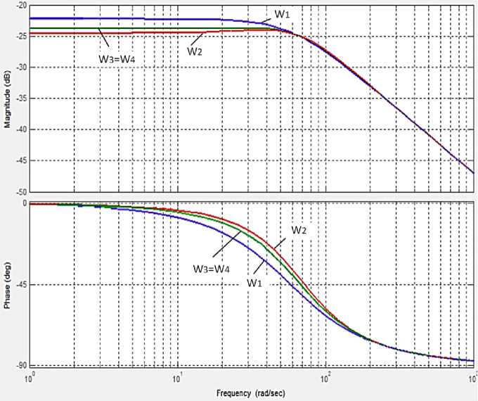
Fig. 6. Frequency responses of the torque driver link: initial ( W 1 , W 2 ) and corrected ( W 3 , W 4 ) for the supply voltage frequency 50 Hz
F or st a t or curr e n t f ee dbac k , the lin e a riza t ion condi ti on will v a r y s lig htly :
U^V 2MkS,.(T ‘ p + 1)^
.
Thi s e xp r e s sion sh ows that wh en controlling the flux linkage, the linearization c on dit ions ca n be r efined, ther eby e ns ur ing hig h qua l it y re g ul a t ion.
On t he oth e r ha n d, it is e as y to show that with some inaccuracy in the fulfillme nt of the lin e a riza t i on condition, i.e.
£ _ 2M k (7 2 p+1)Wt _ д
S k ^ 2 .
The tra ns f e r f unct ion a nd f re que nc y respons e of the torque driver will differ slightly from the transfe r f unct ion a n d fr e qu e nc y r e spo nse o f the f i r st-order linear link.
C onsid e r the ca se of de v iati o n of the parameters of the corrective element by 5% for the fr e quenc i es o f th e supp ly v olta g e of 10 a nd 50 Hz. T he fr equency characteristics of the link of the torque driver with accurate correction ( W 1 , W 2 ) a nd the deviation of the transmission coefficient of t h e c orr e cti on l ink ± 5 % ( W 3 , W 4 ) are presented in Figs . 7 a nd 8.
ТА, _ 3,84
^PFB 1 = 0,0038р + 0,226
^PFB 2 = 0,0038р + 0,226
Fig. 7. Frequency response of the torque driver and transfer functions of the correction link for the stator voltage frequency of 10 Hz, accurate ( W 1 ) and when the transfer ratio of the correction link deviates by 5% ( W 2 )
тд, _ 3,84
^PFB 1 = 0,0038р + 0,226
_ 3,84
^PFB 2 = 0,0042р + 0,226
Fig. 8. Frequency response of the torque driver and transfer functions of the correction link for the stator voltage frequency of 50 Hz, accurate ( W 3 ) and when the transfer ratio of the correction link deviates by 5% ( W 4 )
Conclusion
Thus, the proposed method for analyzing processes in an asynchronous drive with frequency control according to changing transfer functions and frequency characteristics (“families” of functions and characteristics with frozen frequency and slip parameters) made it possible to propose an effective correction, in terms of controllability of a nonlinear dynamic structure, allowing increase its effectiveness.
References Control of nonlinear dynamics of electromechanical systems
- Усольцев, А.А. Частотное управление асинхронными двигателями: учеб. пособие / А.А. Усольцев. - СПб.: СПбГУ ИТМО, 2006. - 94 с.
- Исследования автоматизированных электроприводов, электрических машин и вентильных преобразователей: темат. сб. науч. тр. / под ред. В.А. Лифанова, С.Д. Левинтова. - Челябинск: ЧПИ, 1990. - 160 с.
- Фигаро, Б.И. Регулируемые электроприводы переменного тока / Б.И. Фигаро, Л.Б. Павлячик. - Минск: Техноперспектива, 2006. - 363 с.
- Ещин, Е.К. Электромеханические системы многодвигательных электроприводов. Моделирование и управление / Е.К. Ещин. - Кемерово: Кузбасский гос. техн. ун-т, 2003. - 247 с.
- Marc Perron; Hoang Le-Huy. Full Load Range Neural Network Efficiency Optimization of an Induction Motor with Vector Control using Discontinuous PWM / Marc Perron; Hoang Le-Huy // IEEE International Symposium on Industrial Electronics. - 2006. - Vol. 1. DOI: 10.1109/ISIE.2006.295586
- Соколовский, Г.Г. Электроприводы переменного тока с частотным регулированием / Г.Г. Соколовский. - М.: ACADEMIA, 2006. - 267 с.
- Kodkin, V.L. The dynamics identification of asynchronous electric drives via frequency response / V.L. Kodkin, A.S. Anikin, AA Baldenkov // International Journal of Power Electronics and Drive Systems. - 2019. - Vol. 10, no. 1. - P. 66-73.
- DOI: 10.11591/ijpeds.v10.i1.pp66-73
- Hoang Le-Huy. Modeling and simulation of electrical drives using MATLAB/Simulink and Power System Blockset / Hoang Le-Huy // IECON'01, 27th Annual Conference of the IEEE Industrial Electronics Society. - 2001. - Vol. 3.
- DOI: 10.1109/IECON.2001.975530
- Hoang Le-Huy. MATLAB/Simulink and PSPice as modelling tools for power systems and power electronics / Hoang Le-Huy, G. Sybille // Power Engineering Society Summer Meeting. - 2000. - Vol. 2.
- DOI: 10.1109/PESS.2000.867449
- Champagne, R. Real-time simulation of electric drives / R. Champagne, L.-A. Dessaint, H. Fortin-Blanchette // Mathematics and Computers in Simulation. - 2003. - No. 63 (3-5). - P. 173-181.
- DOI: 10.1016/S0378-4754(03)00065-X
- Dessaint, L.-A. Modelling and Simulation of Electric Machines, Converters and Systems / Louis-A. Dessaint, Kamal Al-Haddad // Mathematics and Computers in Simulation. - 2003. - No. 63 (3-5). - P. 135-143.
- DOI: 10.1016/S0378-4754(03)00170-8
- Kodkin, V.L. Experimental Research of Asynchronous Electric Drive with Positive Dynamic Feedback on Stator Current / V.L. Kodkin, A.S. Anikin, A.A. Baldenkov // III International Conference on Industrial Engineering, Applications and Manufacturing, ICIEAM 2017. - 2017. - https://ieeexplore.ieee.org/document/8076179
- Аникин, А.С. Динамическая положительная связь в асинхронных электроприводах с частотным управлением / А.С. Аникин, В.Л. Кодкин, А.А. Балденков // Приоритеты мировой науки: эксперимент и научная дискуссия: материалы 8-й междунар. науч. конф. Научно-издательский центр «Открытие». North Charleston, SC, USA, 17-18 June 2015. - С. 119-124.
- Коррекция динамических моментных возмущений в электроприводах переменного тока / В.Л. Кодкин, Я.А. Шмарин, А.С. Аникин и др. // Наука ЮУрГУ. Материалы 68-й научной конференции. - 2016. - С. 805-814.
- Пат. 2599529 Российская Федерация, МПК H02P03/04. Устройство частотного управления асинхронным электроприводом / В.Л. Кодкин, Я.А. Шмарин, А.С. Аникин, А.А. Балденков. - № 2014151549/07; заявл. 17.11.2015; опубл. 10.10.2016, Бюл. № 28.
