Conversion use of models of working processes of rocket engine turbine installations in the application to local power engineering

Author: Abroskin V. A., Chernorot V. A., Kishkin A. A., Delkov A. V., Zhuravlev V. Yu.
Journal: Siberian Aerospace Journal @vestnik-sibsau-en
Section: Technological processes and material science
Article in issue: 2 vol.22, 2021.
Free access
In this paper, we consider the concept of using methods for calculating and designing rocket engine power plants for conversion modeling of local energy in the Arctic and northern regions of the Kras-noyarsk Territory, with an obvious generalization to neighboring administrative formations with similar climatic and structural and logistical conditions. The proposed structure contains power generation units linked to both industrial woodworking waste and natural and industrial thermal tails, identified as sources of low-potential heat, as well as modern low-power reactor plants of block maintenance-free design. The unifying element of power plants is a turbo generator, designed with the use of unconventional, often waste and natural low-grade heat.
Jet turbines, centrifugal and centripetal, energy technologies, low-grade heat, geothermal heat, thermal discharges, low-power nuclear power plants.
Short address: https://sciup.org/148321810
IDR: 148321810 | UDC: 621.11; 620.97 | DOI: 10.31772/2712-8970-2021-22-2-356-370
Text of the scientific article Conversion use of models of working processes of rocket engine turbine installations in the application to local power engineering
The experience gathered in calculating the parameters of gas turbine installations of rocket engines makes it possible to apply digital models to technologies for utilizing low-grade heat to create low-power installation.
In the global formulation of the problems of small-scale power generation using fuels from non-conventional sources, renewable and wind energy [1; 2], the autors are consideing the aspects of improving characteristics [3] owing to the detailed study of working processes in power equipment using unconventional rare cycles [4]. In the Russian Federation, the problems of small distributed generation are set and determined with a large coverage.
According to the report of Yevgeny Afanasyev (the head of the Regional Ministry of Industry, Energy and Housing and Communal services) at the 10th International Forum "Arctic: Present and Future", held in St. Petersburg, the power system of the Arctic zone of the Krasnoyarsk Territory includes two hydroelectric power plants - Ust-Khantayskaya and Kureyskaya, three gas CHP plants (combined heat and power plants) providing electricity to the Norilsk industrial region, as well as more than 60 diesel power plants and 48 boiler houses in power-insulated villages. The main problems of the power system of the northern regions are significant equipment deterioration, high cost of fuel delivery, as well as restrictions on the supply of fuel, which is caused by a short period of deliveries of goods to the Northern Territories. The significant share of funds is allocated from the regional budget to subsidize energy generation costs.
The measures taken in the field of energy supply are insufficient for developing the northern regions and creating infrastructure that would create decent social living conditions for the local population and the development of commercial farms.
In order to increase the efficiency of energy supply, in the territory of the Tura settlement of the Evenkia Area, the utilization of waste heat has been introduced at three diesel power plants receiving heat energy in the form of hot water. In Russia as a whole and in the Krasnoyarsk Territory, there are modern energy technologies that can significantly reduce operating cost [5–8].
OOO ITC " Soyuz-Energo" in cooperation with Reshetnev Siberian State University of Science and Technology have developed a unique technology for converting low-grade thermal energy (warm water, warm air and exhaust hot gases, etc.) in the organic Rankine cycle into electricity. This technology is based on the use of an organic low-boiling actuation fluid (freon) in the cycle, in combination with both the typical power range of turbines and the experimental design of a centrifugal jet turbine, which, unlike typical designs, allows working in the area of saturated (condensable) steam without disturbing the operation of the nozzle diaphragm and the turbine, as well as structurally combining part of the function of the circulating supercharger [9; 10] and the turbine, which provides some decrease in energy losses by reducing the mechanical losses of the rotor and increasing the overall efficiency of a turbine [11]. A high-speed permanent magnet generator is used as an electric generator.
Mathematical modeling and engineering calculations were carried out by the OOO ITC "Soyuz-Energo" and the Department of Refrigerating and Cryogenic Engineering of Reshetnev Siberian State University of Science and Technology.
Mathematical modeling
The schematic block diagram of the heat recovery unit based on a steam turbine unit (STU) is shown in
Fig. 1.
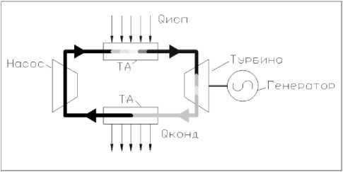
Рис. 1. Структурная схема установки и цикл работы: ТА – теплообменный аппарат; Q 2 – теплота, подведенная в испарителе; Q 1 – теплота, отведенная в конденсаторе; Nt – мощность турбины
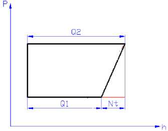
Fig. 1. Block diagram of the installation and its operation cycle
ТА – heat-exchange apparatus; Q 2 – heat supplied to the evaporator;
Q 1 – heat rejected in the condenser; Nt – turbine power
The mathematical model of a steam turbine plant (STP) based on organic actuation fluids (OAF) is based on four basic equations, which, in various interpretations, form the basis of technical hydromechanics and consider the flow of compressible fluids with heat exchange. The equations below are presented for a onedimensional flow in two forms - differential and integral:
– motion equation (Eulerian equation):
dW
Р— = Р F - grad ( Р ); dt
– mechanical energy equation (Bernoulli equation):
р W2
+ p = const;
where ρ – density; W – speed; t – time; F – strength; p – pressure; – equation of continuity in notation of calculus:
d P + р div ( W ) = 0; (3)
– equation of continuity in integral form:
р SW = const, (4)
where S is the passage area of the channel;
– energy-conservation equation in thermodynamic parameters in notation of calculus:
du dq
р— = - pdivW + p D - divq + p— ;
dt dt
– energy-conservation equation in thermodynamic parameters in integral form (First law of thermodynamics):
A U = A + A Q ,
where ^ D - work of viscosity forces; u , U - internal energy; q, Q - heat flow;
– equation of state (in general form) (see Fig. 1):
f ( P , P , T ) = 0. (7)
The four equations contain four independent physical quantities: p , ρ, q , T . Thus, the system is closed. These equations are universal and can be applied to the description of any processes in turbine installations of thermal power systems. The system of these equations can be specified for different levels in accordance with the accepted hierarchy of the model:
-
– the level of final volumes. It considers a geometric volume that is so small that differential equations can be applied;
-
– the level of system elements. It considers a specific element (component of a complex system) – heat exchanger, pump, capillary tube. Accordingly, the equations are integral. At this level, the equations called component equations of an element are obtained,;
-
– system level. It considers the system as a whole and integral equations. In the literature, these equations are called topological equations of the system.
The calculation procedure is shown in the operation cycle diagram (Fig. 2). The differential pressure (1) sets the height of the cycle in the diagram, the heat flux (6) sets the width of the cycle. The cycle is balanced in terms of flow and temperature. The system of equations is solved numerically by iterating the flow rate on the balance of the energy equation. The result of solving the system of equations determines the position of the cycle in the diagram with reference to the properties of the actuation fluid (2), (4), (6), (7).
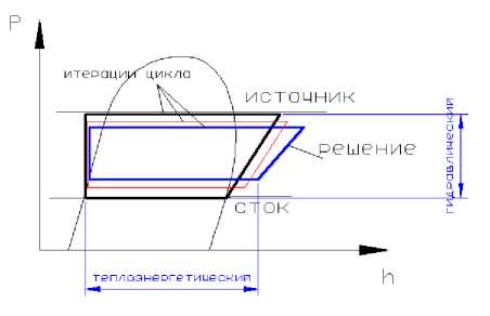
Рис. 2. Определение параметров цикла по системе уравнений
-
Fig. 2. Determination of the cycle parameters using the system of equations
The surface of the actuation fluid state was developed to take into account the changing properties of the actuation fluid. Mathematical state surface (Fig. 3) of an organic actuation fluid in the coordinates of pressure p, specific volume υ (υ = 1/ρ) and temperature T allows calculating the cycles of power plants by numerical methods, taking into account the continuous change in properties. In addition, using the surface, it is possible to obtain basic parameters of a body (enthalpy, entropy, heat capacity, speed of sound, etc.) using differential equations of thermodynamics.
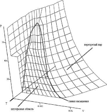
Рис. 3. Поверхность состояния фреона R22
-
Fig. 3. The state surface of R22 freon
The calculated characteristic for the adiabatic power of the turbine accords well with the theoretical results. As the pump head increases, the pressure differential in the system increases as well, and therefore the temperature differential rises (Fig. 4). The specific work of the turbine and the mass flow rate increase.
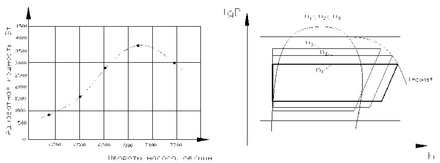
Рис. 4. Реакция ПТУ ОРТ на изменение оборотов насоса
-
Fig. 4. Reaction of the steam turbine unit on the change of pump speed
The results of numerical experiments presented above, along with the reflection of the adequacy of the mathematical model to theoretical information about the operation of the STP, allow us to formulate the following: due to the ambiguity of the influence (including the mutual influence) of the control parameters on the operation of the STP, the OAF design and operation optimization of similar steam turbine plants is a complex problem that involves consideration of the wide range of possible system states. One of the effective ways to solve this problem is the development of algorithms and methods for its solution based on a mathematical model with conducting numerical research.
An installation test bench was designed to verify the model (Fig. 5). To estimate the power of the turbine, the parameters of the amount of energy imparted to water are required, which is estimated by means of the data on the pressure and temperature of the water at the inlet and outlet of the pump. The main element of the laboratory setup is a steam turbine.
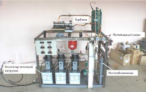
Рис. 5. Испытательный стенд ПТУ на ОРТ
-
Fig. 5. The test bench of a steam turbine unit
Proposed solutions
The analysis of the results of operation of the experimental turbine generator "Thermoel", the design study and calculations show that the turbine generator can provide electricity generation from units to several thousand kW, providing the efficiency factor of 20 to 40% at a coolant (water, gas) temperature of 20 ° C and above.
Currently, two modular turbine generators are being developed for the research bench for melting metal radioactive waste at one of the enterprises of the Rosatom group company [12]. Three-dimensional models of electric generators with the capacity of 100 kW on a single frame and 1 MW in a 20-foot container are shown in Fig. 6.
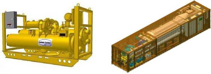
Рис. 6. Турбогенераторы мощностью 100 и 1000 кВт
Fig. 6. 100 kW and 1000 kW turbo generators
We propose to consider the following technical solutions for the creation or modernization of the available local energy systems:
-
– heat recovery with the generation of additional electricity from existing diesel power plants;
-
– local production for the fabrication of domestic fuel oil and pyrocoal from local wood for sanitary cleaning of forests and wood processing waste;
-
– mini CHP plants on local wood waste (sawdust, shavings, wood chips, branches of trees and shrubs);
-
– use of heat from geothermal waters to generate electricity;
-
– use of atomic energy from low-power nuclear power plants to generate electricity and hot water.
Diesel power plants are used most of all to generate electricity in the Northern regions. During the operation of these stations, large amount of waste heat (so-called thermal tails) is emitted into the atmosphere. Thermal tails are generated from combustion exhaust gases, the cooling system of the internal combustion engine and the oil cooling system. For 1 MW of generated electricity, 1–2 MW of heat is generated.
Recently, cogeneration plants have been used for the recovery of thermal tails, providing a combined process – generating electricity and heat in the form of hot water. The unit for waste gas heat recovery and hot water production is shown in Fig. 7.
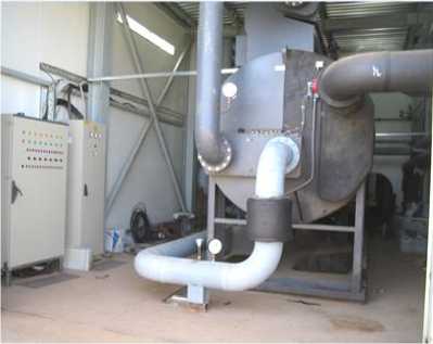
Рис. 7. Установка утилизации тепла отходящих газов
Fig. 7. Waste gas heat recovery unit
One of the promising and cost-effective technical solutions is the creation of an integrated energy centre with combined generation of electricity, hot water and electricity from the heat of hot water. For this, it is necessary to add the “Thermoel” turbine generator module to the cogeneration unit.
With the diesel generator capacity of 1 MW, one can obtain additional 0.5 MW of electricity and 0.5 MW of heat the form of hot water.
At the annual electricity generation of 500 kW • 8,000 hours = 4,000,000 kW • h per year, the revenue from the sale of electricity at the cost of 1 kW • h of electricity of 10 rubles will be 4 million kWh • 10 = 40 million rubles. The payback time is estimated to be 1.1 years. The diagram of the "Thermoel" turbogenerator with the use of thermal tails is shown in Fig. 8.
The northernmost point of wood processing is the town called Lesosibirsk, where wood processing enterprises are located along the river Yenisei for 40 km. Over the years of the activity, the large amount of sawmill waste has been accumulated.
Wood is one of the primary fuel sources. The calorific value of wood is 4600 kcal / kg with the bulk density of 550–600 kg / m3. The calorific value of wood briquettes is 7800 kcal / kg with the bulk density of 600 kg / m3. The calorific value of diesel fuel is on average 10,000 kcal / kg with the bulk density of 800 kg / m3. The analysis of the characteristics of various types of wood briquettes and diesel fuel shows that wood briquettes can fully replace diesel fuel.
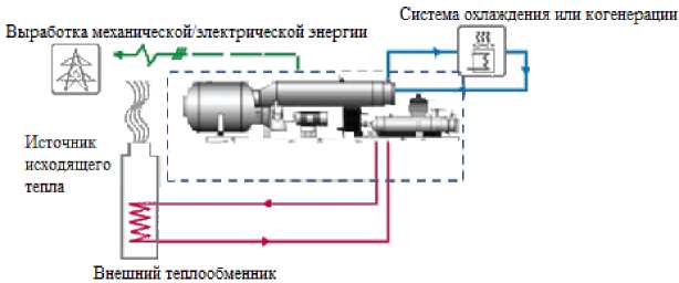
Рис. 8. Схема утилизации тепловых хвостов
-
Fig. 8. Thermal tails recovery scheme
In the last decade, Russian scientists, designers and equipment manufacturers have developed a technology for the rapid pyrolysis of wood waste to produce domestic fuel oil and pyrolytic coal. Modular complexes are manufactured on the basis of the developed technology.
A three-dimensional model of the complex of a rapid pyrolysis plant is shown in Fig. 9.
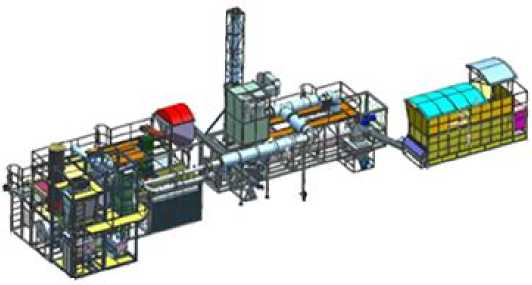
Рис. 9. Общий вид установки быстрого пиролиза с габаритными размерами 31,5 x 7 x 9,1 [м]
-
Fig. 9. General view of the rapid pyrolysis plant with the overall dimensions 31,5 x 7 x 9,1 [m]
Plant specifications:
– productivity, kg / h – 500, dry;
– power consumption, kW * h - 25;
– operating mode – continuous;
– maximum temperature in the reactor, оС – 650;
– maximum temperature in the furnace, оС – 1000.
Yield of pyrolysis products:
– gas, kg / h – 130;
– carbon, kg / h – 100;
– bio-oil, kg / h – 270.
Domestic fuel oil (bio-oil) can be used in boiler houses in remote northern regions, as well as carbon (pyrolytic coal) can be used as a solid fuel with injection of carbon powder into a furnace.
With further distillation of bio-oil, one can obtain:
– phenol-formaldehyde adhesive for the production of plywood and glued wood;
– woody acetic acid – antiseptic and fertilizer for soil treatment.
Currently, Russia manufactures and sells boiler houses with the capacity from 100 kW to 50 MW, operating on wood waste. When using the boiler houses with the turbo generators "Thermoel" it is possible to create an efficient energy system for generating heat in the form of hot water and electricity, as well as to avoid kilometer-long heaps of wood waste in Lesosibirsk.
Fig. 10 shows a three-dimensional model of a modular boiler house with the power of 1-3 MW.
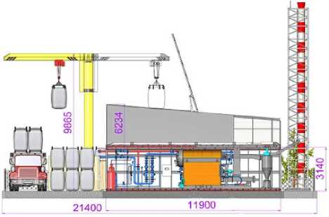
Рис. 10. Модульно-двухблочная котельная ООО «СОЮЗ» тепловой мощностью от 1 до 3 МВт с многотопливными котлами (щепа, пеллеты, брикеты, уголь)
-
Fig. 10. Modular-2-block boiler house of OOO SOYUZ with the thermal power of 1 to 3 MW with multi-fuel boilers (wood chips, pellets, briquettes, coal)
One of the inexhaustible sources of energy is geothermal heat, released as a result of nuclear processes inside our planet.
It is known that there is an amount of water inside the Earth that exceeds its amount on the surface, and due to water heat exchange, heat is released into the atmosphere [9].
The Krasnoyarsk Territory is partially located on the territory of the West Siberian Plain. The geological studies of prospecting for oil deposits, as well as hydrological studies on a vast territory back in the 50s of he last century show that at the depth of several hundred to several thousand meters, there is a hot water source with the volume exceeding the Mediterranean Sea.
Near Biysk, Semipalatinsk or Kustanai, the water temperature reaches only + 5 ... + 10 degrees Celsius, further north, at the latitude of Pavlodar, Petropavlovsk, Tomsk, where the depth is already 500-600 m, the thermometer in the borehole shows +25 degrees Celsius ( Fig. 11).
Even hotter water (+75 degrees Celsius) was found at the depth of 1.5 km near Tyumen. And where it is necessary to drill boreholes to the depth of 2.5-3 km, fountains of boiling water sometimes break to the height of up to 50 m. The temperature of one of these artificial geysers (in Kolpashevo) reaches +125 degrees Celsius.
Russia has experience in using geothermal heat to generate electricity. In 1965, the Institute "Thermophysics" of the Siberian Branch of the USSR Academy of Sciences built a freon geothermal power plant with the power of 1 MW at a geothermal water temperature of 80 ° C in the Sredneparatunskoye field. As a unit for generating electricity, a blade turbine was used, the efficiency of which was no more than 7%, the rest of the heat of hot water was used for heat supply [13; 14].
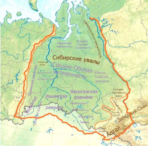
Рис. 11. Геотермальное теплое море
-
Fig. 11. Geothermal warm sea
Using the centrifugal turbine of the Thermoel model, it is possible to create local power and heat supply systems with high energy efficiency in places where thermal waters are available, without damaging the environment. To search for geothermal horizons with the relatively high temperature of 40–70 ºС, it is necessary to carry out engineering-geological and hydrological surveys. A schematic diagram of the use of geothermal waters for electricity generation is shown in Fig. 12.
According to the experience of building geothermal power plants in Europe, the cost of capital investments is 3,000 dollars for 1 kW of generated electricity.
To provide a reliable autonomous system of heat and power supply for small settlements and low-power industries, it is worth considering the possibility of building small nuclear power plants (SNPPs) up to 400 MW. The developments on the creation of SNPPs were carried out 50 years ago. However, they did not end with a specific implementation.
At present, power sources have been developed on the basis of the 35 MW KLT-40S reactor system (RS), the 6 MW ABV-6E RS, and the 50 MW RITM 200 RS [15–17].
The floating power unit with the KLT-40S RS has been built and put into operation, the other two projects have not been implemented yet.
The main advantages of the SNPPs are the following: the ability to create the required power of the SNPP depending on the requirements of consumers; short construction period; environmentally friendly form of energy; long service life (more than 35–40 years).
The three-dimensional model of a floating SNPP and SNPP with the RITM 200 RS is shown in Fig. 13.
The scheme of the modular design of the SNPP with two Master reactors with a thermal power of 30 MW each is shown in Fig. 14.
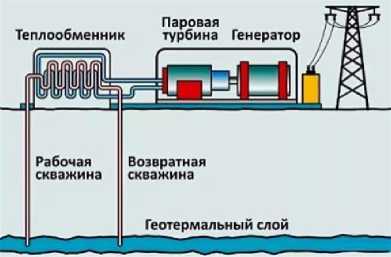
Рис. 12. Принципиальная схема использования геотермальных вод для производства электроэнергии
-
Fig. 12. Schematic diagram of using geothermal water for electricity generation
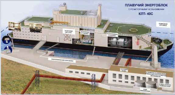
Рис. 13. Модель плавучей АСММ
-
Fig. 13. Model of the floating SNPP
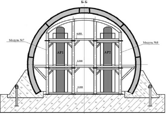
Рис. 14. Схема модульной конструкции АСММ
-
Fig. 14. Diagram of the modular design of the SNPP
Conclusion
The accumulated experience of mathematical modeling of heat and mass transfer and heat power processes in the flow path of aircraft engines allows using the results for individual elements of turbines, pumps, heat exchangers in the Rankine cycle for power generating equipment with the possibility of design optimi- zation of the parameters of both elements and the system with subsequent calculation of the flow path of structural elements.
The promising way of using low-grade energy sources is the use of heat recovery converters based on steam turbine plants using organic actuation fluids with the condensation temperature below 100 ° C.
The considered structure of a low-power distributed power generating system takes into account only individual sources and possibilities of northern and inaccessible territories and is determined by the general requirement for heat sources: a relatively low temperature potential, which requires the development and production of special equipment for turbo power generation, determined by the satisfactory possibility of block transportation and installation, as well as minimum maintenance for a long service life. Undoubtedly, low potential, increased safety requirements and a long service life with minimal maintenance make this area of power generation quite losing in terms of energy efficiency with large power generation. However, only such a performance forms a niche of low-grade energy in hard-to-reach subarctic regions, in our opinion. The materials do not consider other elements of renewable energy, although their use is cogeneratively possible.
References Conversion use of models of working processes of rocket engine turbine installations in the application to local power engineering
- ZhangL., Hu X., LiC., Esmaeili V.,Gholizadeh M. Fates of heavy organics of bio-oil in hydrotreatment: The key challenge in the way from biomass to biofuel. Science of the Total Environment. 2021, Vol. 778, No. 146321.
- Hemmati M., Mirzaei M. A., Abapour M., ZareK., Mohammadi-ivatlooB., MehrjerdiH., Marzband M. Economic-environmental analysis of combined heat and power-based reconfigurable microgrid integrated with multiple energy storage and demand response program. Sustainable Cities and Society. 2021, Vol. 69, No. 102790.
- Gong W., Shen J., Dai W., Li K.,Gong M. Research and applications of drag reduction in thermal equipment: A review (Review).View Correspondence (jump link). International Journal of Heat and Mass Transfer. 2021, Vol. 172, No. 121152.
- Romei A., Binotti M. Off-design performance of closed OTEC cycles for power generation (Article). View Correspondence (jump link). Renewable Energy. 2021, Vol. 170, P. 1353–1366.
- Kishkin A. A., Chernenko D. V., Khodenkov A. A., Delkov A. V., Tanasienko F. V. [Development of low-grade heat recovery units based on the organic Rankin cycle]. Alternative Energy and ecology. 2013, No. 14 (136), P. 57–63 (In Russ.).
- Kishkin A. A., Chernenko D. V., Khodenkov A. A., Delkov A. V., Tanasienko F. V. [Development of low-grade heat recovery units based on the organic Rankin cycle]. Alternative Energy and ecology. 2014, No. 3 (4), P. 35–36 (In Russ.).
- Ermakov M. A., Galimov V. S., Shevchenko Yu. N., Kishkin A. A., Melkozerov M. G. [Design of steam microturbine installations of small distributed power engineering]. Collection of materials of the International seminar held in preparation for IX International Scientific and Practical Conference Mountainous Territories: Priority Areas and Sciences of the Russian Federation. 2018, P. 77–79.
- Tolstopyatov M. I., Zuev A. A., Kishkin A. A., Zhuikov D. A., Nazarov V. P. [Rectilinear uniform flow of gases with heat transfer in power plants of aircraft]. Vestnik SibSAU. 2012, No. 4 (44), P. 134–139 (In Russ.).
- Belousov V. I., Erlikh E. N. [Formation of geothermal energy in Kamchatka: problems and solutions]. Problems of the history of natural science and technology. 2015, Vol. 36, No. 2, P. 306–321. (In Russ.)
- Kishkin A. A., Delkov A. V., Khodenkov A. A., Zuev A. A., Zhuikov D. A. [Design optimization of heat engineering systems operating in a closed loop]. Vestnik SibSAU. 2012, No. 5(45), P. 34–38 (In Russ.).
- Zuev A. A., Kishkin A. A., Tolstopyatov M. I., Zhuikov D. A. [Heat transfer of rotational flows in turbomachines on the basis of a two-layer model of a turbulent boundary layer]. Vestnik SibSAU. 2012, No. 5 (45), P. 127–129 (In Russ.).
- Butuzov V. A., Amerkhanov R. A., Grigorash O. V. Geothermal heat supply in the world and in Russia: state and prospects. Teploenergetika. 2018, No. 5, P. 45–49 (In Russ.).
- Vasiliev Yu. S., Amosov N. T. [Nuclear plants of low power]. Scientific and technical statements of the St. Petersburg State Polytechnic University. 2014, No. 2 (195), P. 26–34 (In Russ.).
- Voropai N. I., Saneev B. G., Ivanova I. Yu., Izhbuldin A. K. Comparative efficiency of the use of low-power nuclear power plants in local power systems in the east of Russia. Nuclear power plants of low power: a new direction of energy development. Vol. 2. Moscow, Akadem-Print Publ., 2015, P. 59–72.
- Ivanov I. E., Kryukov I. A., Shustov S. A. [Numerical study of gas dynamics of small-size gas generators and the jets flowing from them]. Bulletin of the Samara State Aerospace University. 2014, No. 1 (43), P. 112–122 (In Russ.).
- Chernorot V. A., Lapshin B. M., Abroskin V. A. Method of processing solid municipal and industrial waste. Patent RF, no. 2697274, mpk B09B 3/00 No. 2018141008. 2019.
- Abroskin V. A. Centrifugal turbine. Patent RF, IPC F01D 1/32. No. 2017144390. 2018.
