Corrosive fluid effects on volute surface roughness in centrifugal pumps: a computational study

Author: Abbas K., Bhutto A.A., Abubakar A.M., Usman I.U., Sarkinbaka Z.M., Saka T., Alhodali M.a.Ja., Ellouze M.
Journal: Журнал Сибирского федерального университета. Серия: Техника и технологии @technologies-sfu
Section: Математическое моделирование. Численный эксперимент
Article in issue: 1 т.18, 2025.
Free access
Corrosive fluids, namely, hydrogen peroxide (H2O2), hydrochloric acid (HCl) and sulfuric acid (H2SO4) can be used as a working fluid for volute surface roughness to study its impact on an existing H47 centrifugal pump. To analyse the effects of volute surface roughness, ANSYS student version 2023 software was used - wherein; head rise (H), pump speed (N), discharge rate (Q), inlet pressure and roughness height (h) of 20-40 m, 2000 rpm, 144 m3/h, 0 atm and 0.5 m, were respectively specified as initial and boundary conditions in the computational fluid dynamics (CFD) tool. CFD of volute roughness were respectively simulated for all corrosive fluids to obtain pressure and velocity distribution and profile plots of the analysis using fluid constant properties. The presence of volute wall roughness was observed to increase hydraulic losses in the volute when using corrosive fluids. The hydraulic loss in the volute due to wall roughness is influenced by the viscosity of the respective fluids. Denser fluids, like HCl and H2SO4 required more input power for the same flow rate, highlighting the viscosity-dependent nature of hydraulic losses. Smoothing and refining the volute wall may lead to a significant increase in pump performance without compromising impeller flow conditions. Exploring the effects of smoothing and roughening the volute wall on pump performance should be investigated.
Impeller volute, centrifugal pump, corrosive fluids, ansys, surface roughness
Short address: https://sciup.org/146283031
IDR: 146283031 | UDC: 621.671:620.268:004.45
Влияние коррозионной жидкости на шероховатость поверхности желоба в центробежных насосах: расчетное исследование
Коррозионные жидкости, а именно перекись водорода (H2O2), соляная кислота (HCl) и серная кислота (H2SO4), могут быть использованы в качестве рабочей жидкости для определения шероховатости поверхности спирали с целью изучения ее влияния на существующий центробежный насос H47. Для анализа влияния шероховатости поверхности спирали использовалось программное обеспечение ANSYS student версии 2023, в котором в качестве начальных и граничных условий в инструменте вычислительной гидродинамики (CFD) былизаданы подъем напора (H), скорость вращения насоса (N), скорость нагнетания (Q), давление на входе и высота шероховатости (h) 20-40 м, 2000 об/мин, 144 м3/ч, 0 атм и 0,5 м соответственно. CFD шероховатости воронки были соответственно смоделированы для всех коррозионных жидкостей, чтобы получить графики распределения давления и скорости и профили анализа с использованием постоянных свойств жидкости. Было замечено, что наличие шероховатости стенок спирали увеличивает гидравлические потери в спирали при использовании коррозионных жидкостей. Гидравлические потери в спирали из-за шероховатости стенок зависят от вязкости соответствующих жидкостей. Более плотные жидкости, такие как HCl и H2SO4, требуют большей мощности при одинаковом расходе, что подчеркивает зависимость гидравлических потерь от вязкости. Сглаживание и доработка стенок спирали может привести к значительному увеличению производительности насоса без ухудшения условий обтекания рабочего колеса. Необходимо изучить влияние сглаживания и шероховатости стенок спирали на производительность насоса.
Text of the scientific article Corrosive fluid effects on volute surface roughness in centrifugal pumps: a computational study
Volutes are commonly employed as collectors in centrifugal pumps. A volute, the wetted section encircling the impeller within a pump, serves the pivotal function of transforming the kinetic energy inherent in fluid into potential energy. Pumps have great applications in industrial applications. The washing tower circulating pump, as a centrifugal pump, would transport water mixed with corrosive media during the work process, and corrosion is an important reason for increasing the roughness of the wall surface. The wall roughness has an important influence on the pump performance (efficiency). Therefore, surface treatments of the pump are particularly important. Now-a-days centrifugal pump either as single stage or multistage is extensively used in upstream, midstream and downstream oil industries. For example, the upstream oil industry uses it to lift fluid from the wellbore, to deliver fluid in the separation system, etc. Performance characteristics of a pump greatly depend on geometry and surface property of an impeller and its volute. Again, the viscosity which can be defined as resistance to flow has significant impact on head, efficiency and power consumption of the pump [8]. If any centrifugal pump works for a longer period, the surface gets deteriorated because of fouling, cavitation or erosion. The oil industry typically handles multi-phase flow and the phases are oil, water gas and sand. There may be some corrosive gasses also, such as H2S. The acidic gas or H2S reacts with water and forms sulphuric acid (H2SO4) which is highly reactive to the metal. Similarly, CO2 or Cl gives ion for corrosion of metal. These corrosive gasses along with sand-jetting effect, accelerate the erosion. A small amount of sand can initiate pitting on the surface and the new surface is attacked by the reactive gasses or acids. Hence, the pump handling fluid from the well bore or at the surface production operations or at the downstream petroleum processing industries will develop micro-pitting and as a result there will be surface roughness [2, 3]. The main role of the volute is to receive the liquid coming with high velocity from impeller to direct it, then to slow it by reducing the perturbations and thus transforming into pressure an important quantity of its kinetic energy. Due to this fact, the volute is subjected to severe solicitations that can lead to severe damages that make the pump unusable. It is known that the drawing – 104 – elements which determine the characteristics of the volute are the form of the section, the volute angle, the width of the input section and the diameter of its base circle.
2. Material and methods 2.1. Software and Fluids
In this study, ANSYS Software (Student version, 2023) was employed. Corrosive fluids (Table 1) used were hydrogen peroxide (H2O2), sulfuric acid (H2SO4) and hydrochloric acid (HCl).
Table 1. Properties of the Fluids
|
S/No. |
Fluids |
Ƿ (g/cm3) |
Cp (J/kg/K) |
µ (Cp) |
MW (g/mol) |
|
1. |
H 2 O 2 |
1.450 |
2617 |
1.254 |
34.00 |
|
2. |
HCl |
1.169 |
4400 |
2.3cP |
36.46 |
|
3. |
H 2 SO 4 |
1.8302 |
1340 |
26.7 at 20oC |
98.07 |
Head rise (H), volumetric flowrate (Q) and rotation speed (N) specification of the H47 centrifugal pump used is shown in Table 2.
-
2.2. Volute Impeller and Centrifugal Pump Characteristics
-
2.3. Assumptions and ANSYS Utilization
The specified parameters in Table 2 with other volute impeller features specified in Table 3.
Table 2. Centrifugal Pump Specification
|
Pump Type |
H (m) |
Q (m3/hr) |
N (rpm) |
|
H47 centrifugal pump |
20 - 40 |
144 |
2000 |
Table 3. Features of the Volute Impeller Employed
|
S/No. |
Parameters |
Values (mm) |
|
1. |
Shaft diameter, Ds |
40 |
|
2. |
Eye diameter, Do |
124 |
|
3. |
Hub diameter, D h |
106 |
|
4. |
Inlet diameter, D 1 |
125 |
|
5. |
Outlet diameter, D 2 |
310 |
The simulation of flow inside the centrifugal pump was done on the basis of the following basic assumptions, namely steady state condition, constant fluid properties, corrosive fluid flow and an assumed rough wall. Hence, any disturbances in flow due to roughness of the surface were acknowledged. For this study, the model construction and flow simulation were conducted using ANSYS Workbench and ANSYS CFX, respectively. The impeller volute was created using Vista CPD (Centrifugal Pump Design) in ANSYS software design toolbox. The model was created by employing the volute specification given in the Vista CPD. The mesh was auto generated in ANSYS Meshing using the platform in the ANSYS Workbench CFX which produced the most appropriate mesh for the analysis. The Mesh was transferred to the CFX Pre solver for the simulation. The flow simulations were done in CFX-Solver within 100 iterations and all of the simulations were converged within 100 iterations. Hence, the results were viewed in CFD post (Turbo post). Final results were obtained in CFD post per boundary conditions of input and output of the volute at steady state which gives accurate results of the analysis. The standard roughness height of 0.5m was chosen. The software calculator in CFD post gives the results of the parameters such as pressure and velocity. Specifications for the volute design and meshed model are respectively displayed in Tables 4 and 5.
Table 4. Computed Volute Information from the Model
|
S/No. |
Variables |
Values |
|
1. |
Inlet width |
43.9 mm |
|
2. |
Base circle radius |
150.4 mm |
|
3. |
Cutwater clearance |
14.8 mm |
|
4. |
Cutwater thickness |
5.7 mm |
|
5. |
Exit area |
5431 mm2 |
|
6. |
Exit hyd diameter |
82.3 mm |
|
7. |
Length |
150.4 mm |
|
8. |
Cone angle |
6.4° |
Table 5. Mesh Details
|
S/No. |
Parameters |
Action |
|
1. |
Element order |
Linear |
|
2. |
Mesh metric |
Skewness |
|
3. |
Element size |
16.10 |
|
4. |
Node |
145214 |
|
5. |
Elements |
393134 |
|
6. |
Mesh tolerance |
0 |
2.4. Simulation
ANSYS Workbench Vista CPD was used to design the impeller volute geometry and ANSYS CFX was used to simulate the flow. A hybrid initialization was utilized to conduct the simulation and get the desired outcomes. The pressure contour and vector velocity were the research parameters of interest of the simulations. The software provided the results after the study was completed and the simulation had reached convergence. In this experiment, different corrosive liquids (which includes H2SO4, H2O2, and HCl) were the fluid chosen at a rotation speed of 2000 rpm. The CFD post program was used to obtain the simulation results base on the boundary condition. The results from 3 different corrosive fluids were then compared with respect to the objective of the study.
3. Results and discussion
3.1. Volute Model and Boundary Conditions3.2. Pressure Distribution
In Fig. 1, the designed volute model produced by the software is showcased.
Boundary conditions displayed in Fig. 2, are the set of conditions specified for the behaviour of the solution to a set of differential equations at the boundary of its domain. Mathematical solutions are determined with the help of boundary conditions to many physical problems. These conditions specify the flow and thermal variables on the boundaries of a physical model. The pump volute has various components inlet and outlet. The pump volute inlet was defined as a total pressure of 1 atm boundary condition and a mass flow rate at the pump outlet. The other surfaces were given as wall boundary conditions. The internal system considered as wall and rough wall condition is applied.
The wall roughness of the volute had the greatest influence on the performance of the centrifugal pump. To study the influence mechanism of the wall roughness of the volute on the performance of the centrifugal pump, the presented study compared and analysed the internal flow of volute between the rough wall using different corrosive fluids as per the boundary condition of the volute.
Fig. 3–5 is the total pressure contours of the central section of the volute across the corrosive fluids; H 2 O 2 , HCl and H 2 SO 4 .
Fig. 3–5 shows that the maximum total pressure contours of the fluids moving across the rough wall volute of the pump. They are respectively, –280.6 kPa for H2O2, –2325 kPa for HCl and 3188 kPa for H2SO4. Whereas the minimum is –4188, –52360 and –77540 kPa, respectively. Analysis of the working fluid flowing through the rough wall volute reveals distinct characteristics. For instance, the minimum total pressure contours, depicted in Fig. 3–5, highlights the energy state of the fluids. For
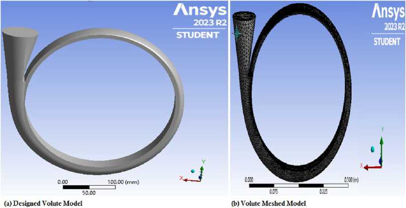
Fig. 1. Volute Model
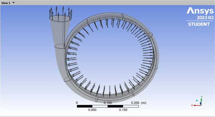
Fig. 2. Boundary Condition
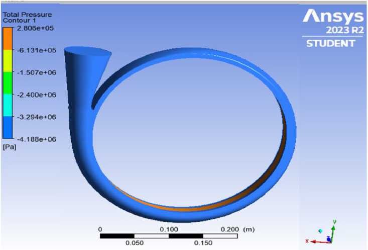
Fig. 3. Total Pressure of H 2 O 2 Flowing Across the Volute
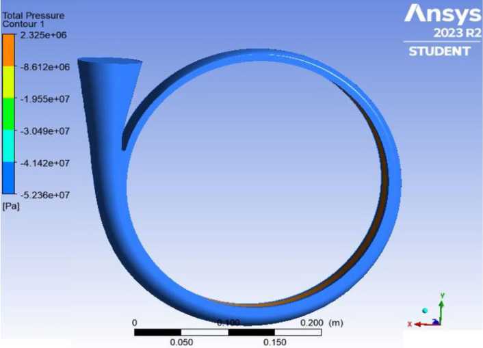
Fig. 4. Total Pressure of HCl Flowing Across the Volute
H2O2, the minimum pressure is denoting the least energy state within the system. In contrast, HCl exhibits a significantly lower minimum pressure, indicative of more challenging conditions for this fluid. On the other hand, H2SO4, with a minimum total pressure contour of –77540 kPa, is the most demanding conditions among the three. The design impeller volute with Q = 144 m3/h has contours of static pressure and liquid flow velocity. The presence of roughness on the volute wall enhanced the hydraulic loss of the volute while employing corrosive fluids, however this was dependent on the fluids' – 109 –
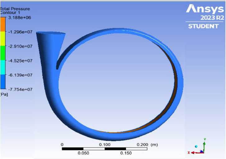
Fig. 5. Total Pressure of H2SO4 Flowing Across the Volute viscosity. Now, comparing the pressure distributions in Fig. 3–5, reveals that both the minimum and maximum pressure of H2O2 remain consistent while those of HCl and H2SO4 vary in both cases.
-
3.3. Velocity Distribution
Fig. 6–8 represents the velocity contours of the corrosive fluids.
Fig. 6–8 shows that the minimum velocity contours of the fluids moving across the rough wall volute of the pump, which are equally 0 m/s and maximums of 77.8, 252.1 and 245.0 m/s for H2O2, HCl
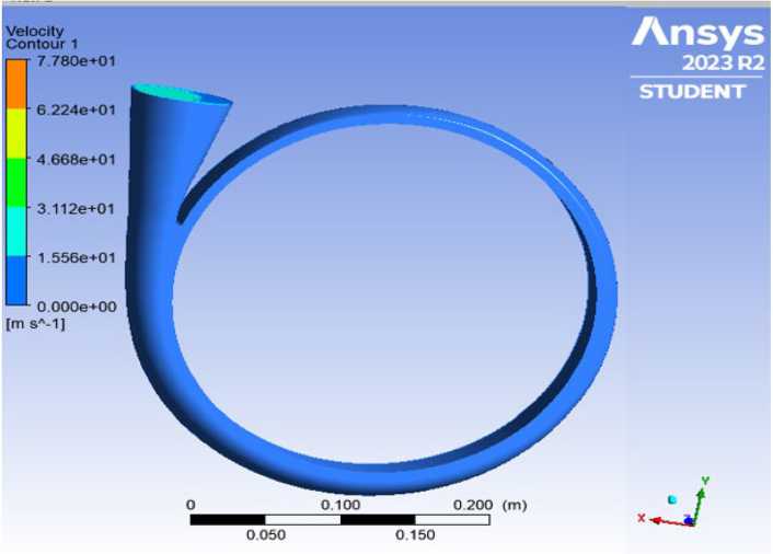
Fig. 6. Velocity Dispersion of H 2 O 2 Across the Volute System
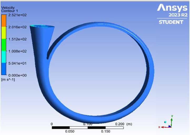
Fig. 7. Velocity Dispersion of HCl Across the Volute Scheme
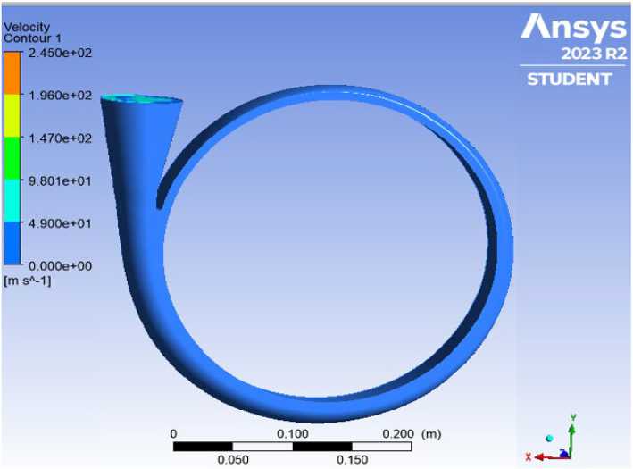
Fig. 8. Velocity Dispersion of H2SO4 Across the Volute Structure and H2SO4, respectively. The diagrams illuminate crucial details regarding the velocity profiles of fluids coursing through the rough wall volute, highlighting the behaviour of H2O2, HCl and H2SO4 corrosive substances. Examining the minimum velocity contours, all 3 substances share a commonality with values reaching 0.00 m/s, indicating areas where fluid motion comes to a complete halt. Contrarywise, digging into the maximum velocity values offers a contrasting perspective, shedding light on areas of heightened fluid dynamics within the volute. It was found that H2O2 reveals a maximum velocity – 111 – indicating localized zones of increased fluid motion despite being the lowest among the substances. On the other hand, H2SO4, showcases considerably more dynamic flow with a maximum velocity suggesting the presence of vigorous and accelerated fluid movements within specific regions of the volute. Surpassing both substances, HCl exhibits the highest maximum velocity signifying areas characterized by intense and rapid fluid flow within the intricate passages of the rough wall volute and the properties of the fluids. This comprehensive analysis of minimum and maximum velocity contours provides a nuanced understanding of the diverse fluid dynamics exhibited by H2O2, HCl and H2SO4 as they traverse through the volute, offering valuable insights for optimizing design parameters and ensuring efficient and effective operation across a spectrum of conditions.
-
3.4. Distributions Profile Curve
The pressure and velocity of each corrosive fluid traveling across the rough wall volute are displayed at the inlet and outlet in Fig. 9.
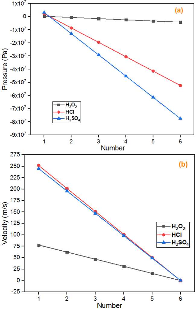
Fig. 9. (a) Pressure and (b) Velocity Distribution Curve/Profile
Fig. 9a displays the pressure distribution curve for various corrosive fluids through the volute's inlet and outlet. It is evident that the line of the volute that used H 2 O 2 as its working fluid relatively decreases while that of HCl and H2SO4 sharply decline with relative distance in between, which is due to different fluid constant properties that highly affect the fluid transportation through the centrifugal pumps. This suggests that the presence of roughness on the volute wall increased the hydraulic loss of the volute that uses corrosive fluids, although the amount of loss depends on the viscosity of the corresponding fluids. Which is the same case for the velocity section of the volute. The impeller volute's efficiency was computed using various mass flowrates for the fluids that were used at 2000 rpm. Denser fluids require more input power for the same flow rate and discharge angle, according to Bellary & Samad [3]. This indicates that the hydraulic loss of the volute when employing corrosive fluids was enhanced by the roughness in the volute wall, however the precise amount of loss is dependent on the fluid's viscosity. Therefore, the roughness of the volute wall increased the frictional resistance loss caused by the fluid flow in the volute and it could be inferred that part to part would not affect each other by the wall roughness. The pump's performance might be significantly increased without having to worry about the impeller's flow condition if the volute wall were smoothed and roughened down. For different fluids at varying mass flow rates, this means that the pressure distribution at the inlet is less and slopes more, while the pressure distribution at the outlet increases with an increase in the blade outlet angle, as reported by Idris & Usman [7]. Velocity profile in volute rough wall of various mass flowrate for various fluid is shown in Fig. 9b. The tangentiall velocity is shown to decrease as the flow progresses through the volute’s route, due to corrosiveness of the working fluids. It is evident that as the fluids moves through the volute wall from its input to its outlet, its velocity increases. As the fluids enters the volute, its velocity appears to diminish, reaching its minimum at the volute’s exit. Furthermore, it is evident that as the cross-sectional area rises, the velocity magnitude in the volute tends to decrease [1].
Conclusion
Presence of volute wall roughness was observed to increase hydraulic losses in the volute when using corrosive fluids. This is evident from the lower total pressure at the outlet for HCl and H2SO4 compared to H2O2. It is observed that the hydraulic loss in the volute due to wall roughness is influenced by the viscosity of the respective fluids. Denser fluids, like HCl and H 2 SO 4 , required more input power for the same flow rate, highlighting the viscosity-dependent nature of hydraulic losses. For HCl and H 2 SO 4 , the significant drop in pressure at the outlet suggests a potential risk of cavitation in the pump due to vapor pressure. This underscores the importance of considering fluid properties and their interaction with rough surfaces in pump design. Smoothing and refining the volute wall may lead to a significant increase in pump performance without compromising impeller flow conditions. This suggests a promising avenue for optimization in pump design. Researchers should conduct research to explore the optimal level of volute wall roughness that minimizes hydraulic losses without compromising impeller performance. Investigate different surface treatments or coatings to mitigate frictional resistance in the volute.
References Corrosive fluid effects on volute surface roughness in centrifugal pumps: a computational study
- Al-Obaidi A., Pradhan S., Asim T., Mishra R. & Zala K. Numerical studies of the velocity distribution within the volute of a centrifugal pump. Presented at 27th Condition Monitoring and Diagnostic Engineering Management International Congress 2014 (COMADEM 2014), 2014, 16–18 September 2014, Brisbane, Australia. https://rgu-repository.worktribe.com/output/872494
- Bellary S. A. I. & Samad A. Improvement of efficiency by design optimization of a centrifugal pump impeller. Proceedings of the ASME Turbo Expo 2014: Turbo Technical Conference and Exposition. Volume 2D: Turbomachinery. [June 16–20, 2014. V02DT42A007], 2D. https://doi.org/10.1115/GT2014–25217
- Bellary S. A. I. & Samad A. Pumping crude oil by centrifugal impeller having different blade angles and surface roughness. Journal of Petroleum Exploration and Production Technology, 2016, 6(1), 117–127. https://doi.org/10.1007/s13202–015–0173-y
- Fard M. H. S. & Boyaghchi F. A. Studies on the influence of various blade outlet angles in a centrifugal pump when handling viscous fluids. American Journal of Applied Sciences, 2007, 4(9), 718–724. https://doi.org/10.3844/ajassp.2007.718.724
- Idris M. N. & Kois A. A. Application of CFD to improve on reliability and efficiency of Centrifugal pump for oil and gas processing plant. African Journal of Engineering and Environment Research, 2022, 3(1), 128–143. https://doi.org/10.37703/ajoeer.org.ng/q1–2022/08
- Idris M. N. & Tijjani A. M. Experimental simulation on impeller volute to determine the surface roughness in centrifugal pump using corrosive fluid. African Journal of Engineering and Environment Research, 2024, 5(2), 1–17. https://ajoeer.org.ng/otn/ajoeer/2024/qtr‑1/06.pdf
- Idris M. N. & Usman I. U. Design studies using corrosive and non-corrosive materials to improve on reliability and efficiency of an impeller of a centrifugal pump. The Electrochemical Society (ECS) Meeting Abstracts, Volume MA2022–02 Z01: General Student Poster Session, 2022, MA2022–02(64), 2345–2345. https://doi.org/10.1149/MA2022–02642345mtgabs
- Kocaaslan O., Ozgoren M., Aksoy M. H. & Babayigit O. Experimental and numerical investigation of coating effect on pump impeller and volute. Journal of Applied Fluid Mechanics (JAFM), 2016, 9(5), 2475–2487. https://doi.org/10.18869/acadpub.jafm.68.236.25094
- Li X., Chen H., Chen B., Luo X., Yang B. & Zhu Z. Investigation of flow pattern and hydraulic performance of a centrifugal pump impeller through the PIV method. Renewable Energy, 2020, 162, 561–574. https://doi.org/10.1016/j.renene.2020.08.103
- Usman I. U., Abbas K., Abubakar A. M., Mönnig R., Abdul A. Z. & Alhodali M. A.-J. ANSYS-CFX simulation and experimental studies on centrifugal pump impeller design: Performance effects using corrosive and non-corrosive resources. International Journal of Engineering and Applied Physics (IJEAP), 2023, 3(2), 765–779. https://doi.org/10.1080/19942060.2020.1868341
- Usman I. U. & Idris M. N. Experimental studies and designs using corrosive and non-corrosive materials to improve on reliability and efficiency of an impeller of a centrifugal pump. In M. N. Idris (Ed.), CHE 599 Proposal Presentation 2021/2022 Session (pp. 1–1). Chemical Engineering Department, University of Maiduguri. 2021. https://www.researchgate.net/publication/356894529
- Varley F. A. Effects of impeller design and surface roughness on the performance of centrifugal pumps. Proceedings of the Institution of Mechanical Engineers, 1961, 175(1). https://doi.org/10.1243/PIME_PROC_1961_175_06
