Crankshaft Online Straightening Technology Determination System Based on Weighted Evaluation Function

Author: Zhai Hua, Zhong Huayong, Zhao Han
Journal: International Journal of Image, Graphics and Signal Processing(IJIGSP) @ijigsp
Article in issue: 2 vol.3, 2011.
Free access
Crankshaft is the most important and hard manufacture part in engine and diesel, its deformation contains multiple arcs, and its straightening technology is a complex NP-hard determination problem. The crankshaft straightening process was analyzed, and some effects from multiple arcs crankshaft straightening was investigated. The mathematics model of multiple arcs straightening technology determination system was built based on graph theory principle. And the Influence of Bauschinger effect was considered, the online straightening technology determination calculation algorithm based on weighted evaluation function was proposed. The experiments about straightening crankshaft were performed in YH40-160 straightening press to evaluate two different weighted set C1={2.5,1.5,1,1.2,3.5} and C2={1,1,1,1,1}, and the results expressed that the online straightening technology determination calculation algorithm was advantage to crankshaft straightening process, and C1 had better influence to qualities and efficiencies than C2.
Crankshaft, online technology determination, weighted evaluation function, straightening
Short address: https://sciup.org/15012122
IDR: 15012122
Text of the scientific article Crankshaft Online Straightening Technology Determination System Based on Weighted Evaluation Function
Published Online March 2011 in MECS
Chinese automobile industry in recent years requires large amount of engine and diesel, straightening technology is the important role in crankshaft machining procedure. Crankshaft is the important components in engine or diesel to withstand impact load and power transmission and can be classified in complex shaft. And crankshaft production increases very rapidly. heat treatment process will hard affects the quality of a forged steel crankshaft machining. Crankshaft was manufactured through some technology such as rough machining, grinding and finished, soft-nitriding heat treatment process and so on, and because of the uneven material and stress release, the crankshaft’s multiple main shaft necks axis line will bend, 8-cylinder vertical arrangement engine forged steel crankshaft rejection rate will be as high as 30% after soft-nitriding, the crankshaft straightening process is the important procedure to reduce processing capacity and quality assurance.
Paper [1] researched the crankshaft comprehensive measuring system to be applied in small crankshaft, and paper [2,3] investigated the affection of plane’s precision to manually measuring large crankshaft. In previous paper, large crankshaft online automatic measuring system in the straightening press had been not seen.
Previous paper[4] analyzed single-curvature bending circle axis, the stroke controlled straightening technology formula had been proposed, but multiple arcs crankshaft straightening technology design theory has not been seen. Multiple arcs crankshaft straightening problem is a NP-hard problem because every shaft neck straightened mutual affection and the Influence of Bauschinger effect.
In this paper, the online automatic measuring system was designed to measure the runout of the crankshaft with the application of the direct touch measuring principle.
This paper also built the mathematic model of multiple arcs crankshaft straightening technology based on analysis of crankshaft straightening procedure and consideration of the Bauschinger effect, and proposed the online straightening technology determination calculation algorithm based on weighted evaluation function. The experiment was performed on YH40-160 crankshaft straightening press, two different weighted set C1={2.5,1.5,1,1.2,3.5} and C2={{1,1,1,1,1} was applied in weighted evaluation function. The results expressed C1 had better influence to qualities and efficiencies than C2, and the algorithm can meet the straightening precision requirements, and is good help to develop the automatic straightening press.
-
II. CRANKSHAFT ONLINE AUTOMATIC MEASURING SYSTEM
A. Previous manual measuring situation
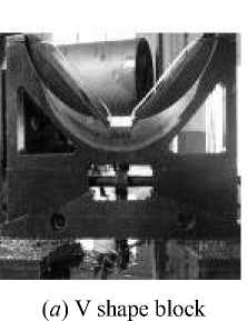
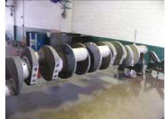
It is difficult to measure large crankshaft manually for the parts’ big weight and complex geometric shapes. Previous manual measuring system equipment was shown in Figure 1 (a) and (b). Multiple points supporting method was applied as shown in Figure 1 (c). To perform measuring 8 cylinder crankshaft with the diameter 152 mm and the length 2.2m, the manual measuring technology steps as followed,
( b ) measuring plane
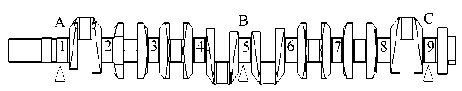
( c ) Multiple points supporting method
Figure 1. Crankshaft manual measuring equipment
-
1) Supporting and fixing the crankshaft, 3 sets of the V shape block were applied to support the 1,5,9 shaft necks on the measuring plane.
-
2) Adjusting operation, the 1, 9 V shape block were adjusted to ensure the same height of two V shape block, the height of A point is equal to the height of C point. Then the height of B points will be adjusted to achieve the height errors with A and C points less than 0.03 mm with the help of height ruler.
-
3) Rotating the crankshaft to measure runout, the crankshaft was slowly rotated manually, the 2,3,4,5,6,7,8 necks runout can be measured through the dial test indicator. The data from indicator was used to determine the shaft qualified or rejected.
The results from multiple points supporting method indicates the straightness of shafts approximately. And the method will take 3 workers and 30 minutes to do the measuring work because of the adjustment work. The results was physically depended on the worker experience. Since off-line measuring operation, there will be multiple shaft movements between straightening process and measuring process, which will bring out the shaft surface injured and knocked, not to ensure the quality. It affects the straightening process efficiency, and not meets crankshaft automatic straightening technology requirements.
B. Crankshaft Online Automatic Measuring System
Based on the direct touch measuring principle[4,5], The measurement system was designed, several sensors with a resolution of 0.5um of differential inductance was used to detect crankshaft, the sensor arrangement shown in
Figure 2. the crankshaft was fixed on the V shape blocks under the 1,5,9 necks . Measuring operation steps are:
-
1) Place the part on 3 V-shaped blocks.
-
2) With the hydraulic system driven, the left center will move right to the fixed position, the right center move left to clamp tight piece, and to ensure axial positioning the work piece.
-
3) The crankshaft was driven by the stepper motor, and the lever sticks the crankshaft surface to achieve the information of the crankshaft.
-
4)
fix nut
sensor fixed nut
sensor
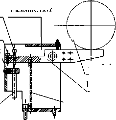
crankshaft
lever
spring
Figure 2 measuring mechanics
adjust nut measure box
C. Crankshaft straightness measuring principle
The outer circle surface on the 1, 9 necks are crankshaft straightness measurement basis. shaft rotates 2°, the sensor for section surface sample 1 points on necks surfaces. Shaft rotates a circle, the sensor will sample 180 times. The sampling data will transport to computer through A/D transformation.
According the principle of least squares, both centers of two ends circular cross section connection lines can be basis axis, the seven middle sections center deviated from the basis axis can be calculated to determine the parts straightness. Assume the sampling values Δ R i j , θ i j are corresponding angles, i means section numbers, i =1,2,…,7, and j is sampling point numbers, j =1,2,…180. From formula (1), the least squares coordinate O i ( X i , Y i , Z i ) of every section can be calculated[6,7].
2 180
Xi = 180 E ( A R cos" '
2 180
Y = V(A R i ,8и^9у ) i 180 ^x iJ iJ
Where Z i — section axial distance 。
From Figure 1, if both centers of 1 and 9 circular cross section connection lines can be basis axis, the seven middle sections center distance W i deviated from the basis axis can be calculated to determine the parts straightness.
W i = V ( X. - a - qZ . ) + Y - b - pZ) (2)
Where a, b, p, q — calculation factors, can be separately calculated from following equations, a = X - X9 X1 x Z , 1 Z 9 — Z1
X9 - Xi q = —9—1,
Z 9 - Z 1
b = y - Y 9 Y 1 x Z , 1 Z 9 - Z 1
Y L- Y L Z 9 - Z 1
So the straightness S is :
S =Max( W 2 , W 3 , W 4 , W 5 , W 6 , W 7 , W 8 )
If S is within the set of [+0.1mm, - 0.1mm], the straightness will meet the requirements and the part is eligible , the part is qualified, otherwise rejected.
D. Software system
Software systems ‘agility’ is very important for the measuring system, the software component of the measurement system was shown in Figure 3, the system has the flexibility in software function features, such as it can be easily used to definite and change several kinds crankshafts on the size and precision by the application with the numeric keypad. It is also can be conventionally calibrated the sensor with standard parts, and can set the tolerance values from the various processing requirements, and can save measuring online data for statistical analysis. According to the results, the manager can evaluate process quality.
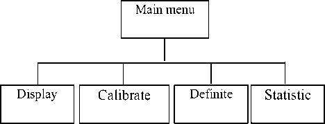
Figure 3 Software system configuration
-
III. MULTIPLE ARCS CRANKSHAFT STRAIGHTENING
Multiple arcs crankshaft straightening problem is a NP-hard problem. The deformation of 8-cylinder vertical arrangement engine forged steel crankshaft was shown in Fig. 4, Fig. 4 (a) expresses the crankshaft whole bends, and (b) means side part of shaft bends, (c) means end part of shaft bends. To reduce the above bending and ensure the shaft straightness qualities, three load methods were applied,
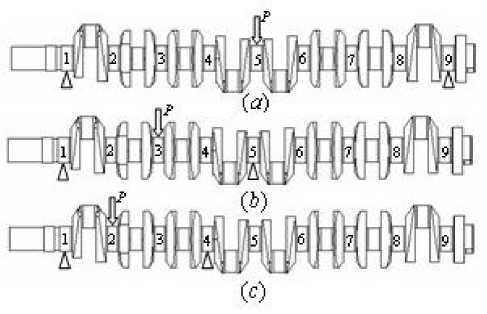
Figure. 4 Three bend deformation of crankshaft
-
1) To straighten the crankshaft whole bend deformation in Fig. 4 (a), the first and ninth shaft necks were supported and the load was performed on the fifth shaft neck.
-
2) To solve the deformation in Fig. 4 (b), the first and fifth shaft necks were supported and the load was performed on the third shaft neck.
-
3) To reduce the second shaft neck deformation in Fig. 4 (c), the firstand fourth shaft necks were supported and the load was performed on the second shaft neck.
During straightening crankshaft process, the hard work is the last load method. Because the crankshaft’s arm’s affection, the third shaft neck was easily bended after the second shaft neck was straightened well. So the second load method must be performed to accomplish the straightening process.
When the initial crankshaft deformation belongs to 3 dimension type, the straightening process will be a complicated technology determination problem and is a NP-hard problem.
Assuming Y1(Z1, Z2) means a combination of straightening press point number and two support point numbers. The press point number and support point numbers sequence was designed according to technology arrangement, increased step by step from left to right. The direct straightening alignment is performed according to the value of every shaft neck straightness, the shaft neck with the largest deformation value will be first straightened. So the straightening sequence may be
-
Y 5 (Z 1 , Z 9 ), Y 3 (Z 1 , Z 5 ), Y 7 (Z 5 , Z 9 ),
-
Y 2 (Z 1 , Z 4 ), Y 8 (Z 6 , Z 9 ).
The second shaft neck section straightness will be reduced in the design requirement after press with the combination of Y 2 (Z 1 , Z 4 ), but its straightening process will affect the third, fourth shaft necks straightness, whose straightness may be good before straightening the second shaft neck as shown in Fig. 5. those affection are,
-
1) the third shaft neck will bend, but there is no variation with and the angle.
-
2) there is a positive effect to the deformation of the forth and fifth shaft neck section.
Because of the rotational angle from the elasticplastic deformation in single arcs part straightening process, the part of the shaft without two supporting points will rotate around the supporting points. So every shaft neck straightened will mutual affect each other.
Another affection is the influence of Bauschinger effect. When the shaft is second pressed against the direction along which the shaft straightened first, the deformation will be increased because of Bauschinger effect. So if the second neck section deformation angle is against to the third neck deformation angle, there will be Bauschinger effect, and stroke algorithm will be not suit for the phenomena, the straightening stroke will make the shaft more bend or even break the shaft.
P Straightening state
-
3 Complete state
-
4 5
Initial state
Figure 5 Multiple arcs deformation shaft straightening mutual affection
If straightening sequence is previous arrangement, the bend crankshaft will be hard straightened. There is straightening loop phenomena, and the straightening time will increase and the efficiency will decrease.
The straightening sequence is the important role to ensure the straightening efficiency and quality. These are just 5 combinations situation, the situation of multiple pressure points, multi-curvature bending, and the number of integrated every section straightening uncertainties, makes the problem will become more complex decisionmaking.
-
IV. MULTIPLE ARCS CRANKSHAFT STRAIGHTENING mathematics model
From the perspective of combination mathematics, the straightening sequence can be expressed as the network map. The combination set of press point and support point can be built through complete listing all of possible combination, and then remove those combination without meeting the requirements such as combination Y 8 (Z 1 , Z 5 ).
The every combination in set can be a node. The straightening process can be simulated as that some nodes can be visited from some initial node beginning. The condition of ending visit is that all of shaft neck straightness will meet the design requirement. The length of two node expressed the straightening times. Fig. 6 shows the straightening situation in Fig. 4, the possible combinations set of press point and support point were Y 1 (Z 1 , Z 4 ), Y 1 (Z 1 , Z 4 ),
From Fig. 6, multiple arcs straightening process was simplified multiple single arc straighten problem. The line length of two nodes depends on the straightening times, the node can be visited many times, or it has not opportunities to be accessed. Consider the shaft neck mutual affection, the new line length will be affected by the previous line length, and the choice of the next node visited will be performed after straightening the departure node. The solution of multiple arcs straightening technology problem is that the distance of all lines in the Fig. 6 is the shortest.
If the straightening decision problem is idealized as the following assumptions,
-
1) Every node can be visited one time.
-
2) The length between two nodes is constant.
-
3) Traversal of all nodes in straightening technology determination map can ensure straightening result.
According to the graph theory, to get the result of the shortest distance on the basis of traversal of all nodes, the minimum spanning tree method can be applied such as Prim algorithm and Kruskal algorithm[5]. When the initial deformation value at every shaft neck is very large, the assumptions will be approximate set up.
The comparison between straightening technology problem and TSP problem[6] in the combination mathematics can be done, it is clear that straightening technology problem is more complex than TSP problem. And consider measuring work after every straightening process, the feedback link can revise straightening path direction, so the problem Increase the difficulty of solving and is NP-hard problem.
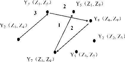
Figure 6 The multiple arcs straightening technology determination map
The straightening technology determination problem can be further abstracted the following optimal mathematics model. If the total number K of straightening times andp shaft necks initial deformation set △ = { 6 10, 5 20, — , 6 p0} were known, and p shaft necks initial deformation angle set 0 = { 9 10, 9 20, — , 9 p0} was known, there isp press points and q supporting points, q ^p, the combination set of press points and supporting points is Z={Yi(Zj1, Zj2) | j1 ^i^j2}, i=1, 2, —, p}, j1, j2=1, 2, —, q. after the k th straightening, the p shaft necks measuring deformation set is △c = { 6k 1c, 6k2c, —, 6kpc}, p shaft necks initial deformation angle set 0k = { 9k 1c, 9k2c, —, 9kpc}, and the mathematics model of straightening determination problem can be stated as followed, to minimize the number of k, and while the following global objective function can be established, p max {Sic} < £ (3)
i = 1
Where e — the shaft straightness error.
The rolling optimal problems at every straightening process can be established through computation of the stroke ykx, min(m"ax S = f. (A 0,0 k, x, ykJ}) (4)
i = 1
Where x — straightening press points number, x ∈ {1,2,…,p} yx — the stroke at the xth shaft neck fi — the function to affect other shaft neck at the xth shaft neck
To compute simply, f i can be assumed to linear function
f ( A k o , 0 k , x , y k ) = a x y x + b x y xo
Where a ix 、 b ix — the factors to affect the i th shaft neck deformation at the x th shaft neck
The choice of straightening press point is limited as followed condition
-
1) the shaft neck section with the largest deformation will be first straightened.
-
2) those shaft necks deformation at the same side have the priority to straighten.
-
3) When straightening two times at the same shaft neck, to reduce affection of Bauschinger effect and avoid reverse straightening bend phenomena, some following conditions must be satisfied
| e x - e x -1| ^ [5 П 6,7 П 6]
-
4) When the difference between two end deformations and the middle part deformations is not large, two end shaft necks should be straightened first and then the middle part according to the deformation theory of 3 points bend.
At present, there is experience method to solve the straightening determination problem according to worker experience. According to collection of the measure information after every straightening process, the straightening sequence can be established to the situation of the same material, same machine history, same deformation regular pattern.
From the experience, some node which represents combination of press point and supporting points can be visited impossible and will be excluded to reduce the problem complexity of straightening determination problem. The finally result is a fixed straightening sequence.
But the experience method must be performed on the basis of a amount of experiments, and can not lend itself to some changes in material, deformation regular pattern. The method can not solve the most optimal sequence theoretically.
-
V. STRAIGHTENING TECHNOLOGY DETERMINATION METHOD BASED ON WEIGHTED EVALUATION FUNCTION
Because the objective function value can be received through measuring feedback link after straightening process with a combination, the objective function value can be forecasted according to some formula and experiences before straightening. It is difficult to applied the global objective function value to search the optimal value, the weighted evaluation function can be built from the priori knowledge and experience, whose basic methods is that the shaft neck with the largest residual deformation comprehensive value will be straightened priority, and it is contribution to the global objective function value reduction.
In practice, the operating procedures is followed,
-
1) Some node can be visited impossible and will be excluded, the uniqueness combination of press point and supporting point can be arrange at a shaft neck, and the weighted value c i ( i =1,2, … , p ), was endowed on the combination. The value of c i will be decided from the experience, or online adjusted with the measuring feedback.
-
2) When choose the new combination, the residual deformation comprehensive values on every shaft necks can be computed through the residual deformation plus the value of c i , and then sort the sequence of the comprehensive values from big to small, the largest comprehensive value can be sought, and recorded the angle of the neck section,
p max{Qi} i=1
Where Q i — neck section weighted comprehensive value, Q i = c i × δ ic .
After the neck section with largest comprehensive value was straightened, every neck section deformation and angle should be measured, and then imitating the way, computing the comprehensive value and sorting.
Consider the Bauschinger effect, the section with its angle same with the last section angle should be straightened priority to other section. So the largest comprehensive value in the sequence should be sought with the condition its angle same as the previous straightening angle, the correspond combination is the result. In Practice, if the angle set at the xth cross section after the kth straightening, Θ k = { θ k 1c , θ k 2c , … , θ k pc }, was known, and the k +1 th straightening combination need be determined, the weighted values can be computed as the following formula,
' c. e k + 1 - e-\ e [0, П 6]
_- C . e x + 1 - e i\ ^ [0, n 6]
When all sections on the same deformation direction be straightened in the design requirement, the section against the direction can be choose to be straightened to ensure the shaft quality. During straightening in the direction, the initial stroke variation should be paid attention[7,8], the stroke can be computed as, ytf=kbXyt
better than the experimental results with the weighted factor set C 2 .
where y tf— the largest reverse elastic recover stroke k b — the factor of the Bauschinger effect y t —the largest positive elastic recover stroke
When all sections on the same deformation plane be straightened, other deformation planes should be chosen according to the plane angle error smallest with the previous plane angle, the straightening determination flow chart was shown in Fig. 7.
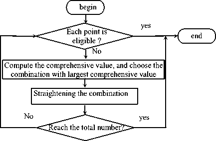
Figure 7 the straightening determination flow chart based on weighted evaluation function
-
V . EXPERIMENT
The weighted evaluation function had been applied in the YH40-160 straightening crankshaft press as shown in Fig. 5, and some crankshaft straightened experiments were performed on the press to achieve the crankshaft straightened purpose.
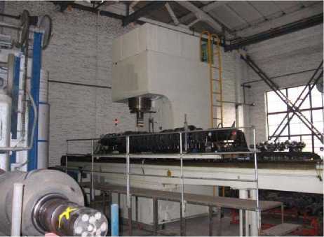
Figure 8 The experiment about straightening determination based on weighted evaluation function on YH40-160 press
Some comparison experiment about the various weighted factor had been done, the weighted factor set respectively choose C1={2.5,1.5,1,1.2,3.5} and C2={1,1,1,1,1}, every crankshaft must be straightened in experiment, the results was shown in Table 1 without the initial eligible and rejected shafts. From Table 1, the experimental results with the weighted factor set C 1 were
|
T able 1 the experimental results with various weighted FACTOR SETS |
|||||
|
Weighted factor sets |
Longest machining time/min |
Machine number /pic |
Qualified number /pic |
Total time /min |
Efficiency pic/min |
|
C 1 |
4.2 |
15 |
12 |
40 |
0.3 |
|
C 2 |
5.8 |
15 |
9 |
55 |
0.16 |
-
VI CONCLUSIONS
The multiple arcs straightening determination problem is analyzed to be a combination optimal problem in this paper, and the mathematic model was built, and it belongs to the NP-hard problem and difficult to get the optimal values. The straightening determination method based on weighted evaluation function was proposed, and put forward a weighted evaluation function, The experiments about straightening crankshaft were performed in YH40-160 straightening press to evaluate two different weighted set C1={2.5,1.5,1,1.2,3.5} and C2={1,1,1,1,1}, and the results expressed that the online straightening technology determination calculation algorithm was advantage to crankshaft straightening process, and C1 had better influence to qualities and efficiencies than C2.
Acknowledgement
This paper was sponsored by National Significant Science and Technology Special Articles (2009ZX04004-021), and Anhui Province Natural Science Foundation(090414155)
References Crankshaft Online Straightening Technology Determination System Based on Weighted Evaluation Function
- S D Phillips , B Borchardt et al . The estimation of measurement uncertainty of small circular features measured by coordinate measuring machines. Precision Engineering, Vol. 22 :pp.87-97. February 1998
- L C R Carpine , D G Chetwynd. A new strategy for inspecting roundness features. Precision Engineering , Vol. 16, pp.283-289.April, 1994
- Ni Xiaohua, Deng Shanxi, Lv Guoqiang. Step-shaft Multi-parameters On-line Measuring System. Tool Engineering. Vol24:pp. 37-39. July 2000
- Zhai Hua, Research on straightening technology CAM system. Chinese Journal of Mechanical Engineering, Vol.16, pp.175-177, June 2003
- Wang Shiyuan. Data structure and application of data base .Tianjing:Nankai University press.1999 (In Chinese).
- Xing Wenxun, Xie Jingxing. Modern optical Calcunlation Algorithm. Beijing:Tsinghua University press, 1999 (In Chinese).
- Brovman M Ya. Effect of rotation of circular beams on their elastic-plastic bending deformation. Mechanics of Solids. Vol.19, pp.155-161,March 1984
- Schmidt W. Influence of residual stresses on the mechanical properties of steel. VDI Zeitschrift. Vol.119, pp.1038-1042, November 1977
