Cross Layer Transmission for AOS Packet Service

Author: Bi Mingxue
Journal: International Journal of Computer Network and Information Security(IJCNIS) @ijcnis
Article in issue: 1 vol.3, 2011.
Free access
In this paper, the AOS packet service data transfers structure is presented first. Based on it, the effective throughput rate of AOS packet service is analyzed. Then, in order to improve the effective throughput rate, a scheme of AOS cross layer transmission system is presented. In the proposed scheme, based on the space channel state, the dynamic optimization parameters of network layer, Space Date Link Protocol sublayer and Sync and Channel Coding sublayer in AOS are selected. Then the switch thresholds are presented. Finally, the effective throughput rate of the proposed AOS cross layer transmission system is simulated. Simulations show that the throughput rate can be optimized effectively.
AOS, packet service, cross layer transmission, effective throughput rate
Short address: https://sciup.org/15011005
IDR: 15011005
Text of the scientific article Cross Layer Transmission for AOS Packet Service
Published Online February 2011 in MECS
AOS is used to manage and transfer various space mission data, such as the exploring and controlling data, the space communications data and other effectual loads data, over the space-to-ground, ground-to-space or space-to-space communication links. The packet service of AOS is used for the efficient transfer of various type packet data. It needs to offer high speed and reliability for various space mission packet data and afford the Quality of Service for end to end transfer.
However, the time variety character of space link will limit the system throughput performance of AOS. So it is important to conquer the effect of space link (or physical channel) for improving the AOS packet service effective throughput rate. The throughput performance of AOS packet service has been studied by reference [1] which discusses the impacts of frame length and the relevant solutions on the throughput. Especially one adaptive technique with dynamic sizing of the Space Date Link Protocol sublayer frame explored. It shows that optimal sizing of the SDLP sublayer frame in the presence of varying channel noise indeed has a large impact on the user seen throughput. In addition, it shows that adaptive frame length control can be exploited to improve a desired level of throughput, and to extend the usable radio range with graceful throughput degradation. But it assumes the modulation is the same and only maximum transmission unit changes according to the space channel conditions to improve AOS throughput, range, and efficiency. And the cross layer transmission scheme has not proposed. However, in wireless systems, recent research has advocated many link layer techniques including error control, channel state dependent protocols and variable spreading gain and the cross layer techniques are generally used to enhance the throughput performance through adapting the different layers transmission parameters to the variations of the wireless channel. Nowadays, the concept of cross layer has been widely accepted. As a result, a large number of cross layer design proposals have appeared in the recent reference [2]-[8].
In this paper, a cross layer transmission scheme of AOS packet service is proposed to increase the AOS packet service effective throughput rate based on intrinsic relations between the channel state, the throughput rate and each parameter of AOS different layers. To detail the principle and performance of the proposed scheme, the remainder of the paper is organized as follows: A brief explication of the AOS packet service data transfers structure and cross layer structure is given in section 2 and section 3 respectively. In section 4, AOS effective throughput rate formula of is introduced and analyzed. Then the AOS cross layer system is designed in section 5, followed by concluding remarks drawn in Section 6.
-
II. AOS D ATA T RANSMISSION S TRUCTURE
The AOS data transfers structure is layered. Comparing with OSI, AOS packet service structure is shown as Fig. 1.
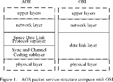
The AOS standard advises that the continuous data from upper layers are partition to be variable length packets in network layer. The different packet service data transferring from network layer are partition to be fixed length transfer frames in Space Date Link Protocol (SDLC) sublayer. Then, these AOS transfer frames are coded and placed an Attached Sync Marker (ASM) in Sync and Channel Coding (SCC) sublayer, and send in physical layer. The traditional AOS layered structure is designed for the worst or the average space channel, and the communications in adjacent layers is invariable. It is unable to adapt the time-varying capacity and high bit error rate ( BER ) space channel. Consequently, increasing the throughput performance requires a cross layer joint design and optimization approach to dynamically adjusting the parameters of different layers.
-
III. AOS C ROSS L AYER T RANSMISSION S TRUCTURE
The cross layer transmission structure of AOS packet service is shown in Fig. 2. Obtaining the channel Signal Noise Ratio ( SNR ) from the estimator, controller decides the packet length of network layer, the frame length of
SDLP sublayer, and coding efficiency and frame sync parameters of SCC sublayer to maximize the AOS packet service effective throughput rate.
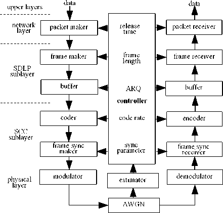
Figure 2. AOS cross layer structure
The AOS cross layer system is research with following presumptions and variable introductions:
-
• SNR of current channel can be check and feed back to the sender accurately.
-
• The frame queue in SDLP sublayer is saturated and the “bad” frames can be detect and drop reliably with CRC field.
-
• T effective is the AOS effective throughput rate.
-
• E up is the efficiency of upper layers. It relates to service PRI and AOS multiplexing.
-
• L frame is the length of frame.
-
• L packet is the average packet size.
-
• L paciet c is the length of packet header and control field.
-
• L frame c is the length of frame primary header and CRC field.
-
• L frame opt is the optimized length of frame.
-
• L frame_ada is the adaptive length of frame.
-
• L flm is the length of Frame Length Marker.
-
• E frame is the efficiency of frame.
-
• R code is code rate.
-
• E sync is the efficiency of frame sync.
-
• L ASM is the length of ASM.
-
• R moduiation is modulation rate.
-
• P sync is the successful probability of frame sync.
-
• P success-jrame is the successful probability of receiving frame.
-
• R is the symbol rate of physical channel.
-
IV. A NALYSIS OF AOS E FFECTIVE T HROUGHPUT R ATE
The effective throughput rate is the ratio of successfully received bit numbers to the total sending bit numbers. Based on the section 3, we have:
T,, = EE , .E, R ,E R
effective up packet frame code sync modulation
■ P PR
success_sync success_frame
Where,
E , . = packet
Lpacket
Lpacket_c
Lpacket
E =
frame
L
frame
L
frame_c
L
frame
f ( l ) = y ^exp(- — l —) (5) packtet packtet
Then packets are multiplexed to be a Multiplexing Protocol Data Unit (M_PDU) and transferred on a VC transfer frame. During a fixed mission phase, the length of M_PDU packet zone L M _ PDU is fixed and we assume that N is the maximal number of available packets which are multiplexed in a M_PDU packet zone at release time T r . If there are insufficient packets arrived at T r , the idle packets will be contained in the M_PDU packet zone. And if the number of packets arrived exceeds N at T r , packets need to be split to fill the M_PDU packet zone completely, and start a new M_PDU on the same VC with the remainder. In this paper, the units of packet size and frame length are octet.
Letting P ( n ) be the probability of n packets has arrived at T r . The process of packets arriving can be modeled as a Poisson process with the average arriving rate λ p one per millisecond, then we can get P ( n ) as
( A p T ) n exp( - 2 p T )
P( n )=—---:——
n !
Esync
frame
Lframe + L ASM
So the efficiency of M_PDU E M_PDU can be express as
-
Obviously, the parameters of each layer affect the
AOS effective throughput rate. So combined optimization can enhance the effective throughput rate.
N м “
£ n£ lf (l)dlP(n) + ^ NLpP(n)
7 _ n =0 _______________________ n = N +1 ____________
'M _ PDU = y
LM _ PDU
-
V . D ESIGN OF AOS C ROSS L AYER T RANSMISSION
The AOS packet service transfers a sequence of variable-length, delimited, octet-aligned service packets which must have a Packet Version Number (PVN) authorized by CCSDS. So in AOS packet service, the packet processing, Virtual Channel (VC) generation, VC multiplexing, the frame framework, and sync and channel coding affect AOS effective throughput rate mainly.
-
A. Design of Packet Release Time in Network Layer
A sequence of variable-length packets are transferred from different data sources. The size of each packet is an exponential distributed variable, i.e.
' N м
I ( A p T r ) n /( n - 1)! + N £ ( A p T r ) n / n !
n = 1 n = N + 1
■
Lpacket exp( -^ pTr ) LM _ PDU
Assuming L packet =100bytes, L M_PDU =1000octets, N =10, the relations of E M_PDU to T r with different values of λ p are shown as Fig.3.
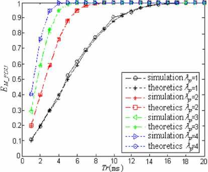
Figure 3. the relation of E M_PDU and T r
From Fig.3, we can see that the simulation results are close to the theoretic results. So the reliability of (7) is proved. We also know that if T r is long enough, E M_PDU will trend to the maximum value 1 and the larger λ p is, the shorter T r for a M_PDU will be. So we assume the T r is long enough.
-
B. Design of Frame Length in SDLP Sublayer
If the effect of SCC sublayer and the repeat transfer frame are not considered, the frame error rate FER can be expressed as
FER=1-(1-BER)8Lframe
So we can get P success _ frame as
Psuccess_frame =1-FER=(1-BER)8Lframe
Substituting (2) ~ (4) and (9) into it, let (1) (10).
∂ ln Teffective =0 ∂ L frame
satisfies
+( Lframe _ c - LASM ) (11)
From (11), we can obtain that L frame_opt is only determined by BER .
Based on the analysis above, we present a frame length adaptive scheme. Before sending data, a pretreatment which chooses an appropriate frame length according to the channel states. The pretreatment can be performed by software, which needn’t change the AOS architecture, so it is can be realized easily. Apparently, L frame_opt is continuous in (11). However, continuous frame length may increase the system complexity and cause performance instability. The discrete frame lengths are more suitable for the practical data transmission, and the frame length being an integer times of byte can be treated easily. As Table 1, the discrete frame lengths 128, 312 and 1024 bytes are considered and the Frame Length Marker ( FLM ) is defined. We define the FLM in frame primary header as Fig.4. So, L FLM =2bits.
TABLE I.
SELECTION OF FRAME LENGTH AND FLM
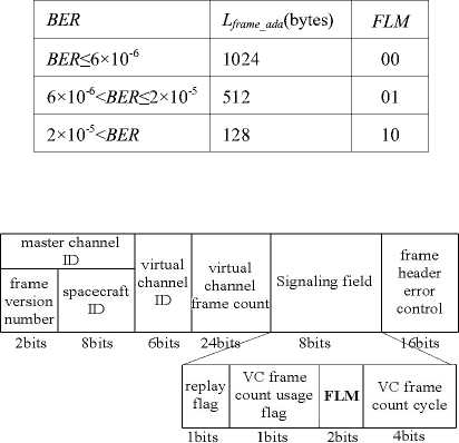
Figure 4. design of frame primary header
Then we can get L frame _ opt maximizing the throughput
as
Lframe_opt
(L frame_c
Ч -
+ LASM ) -( Lframe _ c + LASM )
8ln(1 - ber )
Letting L frame_c =12bytes, L ASM =8bytes, and R =1symbols/s, T effective with L frame_opt and L frame_ada is shown in Fig. 5.When BER >10-4, the communications will be stopped because of too low T effective . Fig. 5 shows that T effective with L frame_ada is close to which with L frame_opt . So if channel states change, T effective can be improved effectively by the proposed adaptive frame length
scheme compared with fixed frame length scheme, and the switch frequency of frame length is not as high as the optimal length scheme.
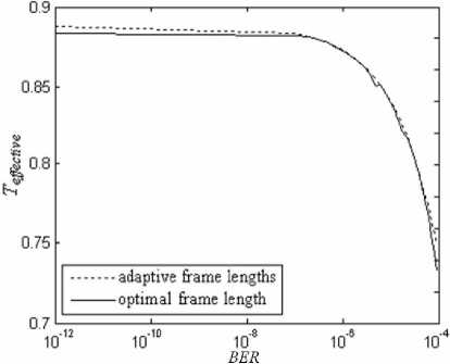
Figure 5. T effective with optimal and adaptive frame lengths
C. Design of ARQ in SDLP Sublayer
Usually, space networking has to deal with hazardous communication conditions, such as long propagation delay, intermittent link connectivity, and high BER . In this environment, the employment of conventional automatic repeat request (ARQ) scheme is encouraged and specific protocols are preferred in order to assure the reliability of the data communication. In this view, a possible choice is represented which implements an enhanced ARQ scheme based on negative acknowledgments (NAK).
Setting the maximum times of every frame transmission is K max , the efficiency of ARQ can be get as
D. Design of Code in SCC Sublayer
Low Density Parity Check (LDPC) code is a class of block codes with near Shannon limit performance. It can provide very low error floors and very fast iterative convergence. These qualities make LDPC code a good fit for near Earth applications where very high data rates and high reliability are the driving requirements [9]. And LDPC code has been submitted to the CCSDS channel coding in the fall 2002 Houston meeting. In this paper, the linear block code is designated by ( L frame , R code ). Fig. 6 shows the FER (solid) and the simulation FER (dashed) for the LDPC codes by BPSK modulation in physical layer. From left to right, these six codes have parameters (128, 1/2), (512, 2/3) and (1024, 4/5).
The simulation FER can be implemented as (15), and the simulation parameters are shown as Table II.
FER = p exp(-q ⋅ SNR) (15)
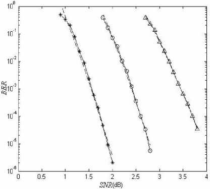
Figure 6. FER for the LDPC codes
EffARQ = max
[ ∑ k ( FER ) k - 1(1 - FER ) + KmaxFERKmax
k = 1
1 + FER
(1 - FER ) Kmax
However, the frame error ratio after ARQ is
- 1
]
FERARQ = FERK max (13)
TABLE II.
THE SIMULATION PARAMETERS FOR FER
|
model |
L frame_ada |
R code |
p |
q |
|
1 |
128 |
1/2 |
109.56 |
21.55 |
|
2 |
512 |
2/3 |
10.12 |
2.23 |
|
3 |
1024 |
4/5 |
9.81 |
1.87 |
So we can get P success _ frame as
Kmax success _ frame
E. Design of frame sync in SCC Sublayer
Frame sync is achieved by sync of an ASM associated with each LDPC Code block. The ASM is a bit pattern of CCSDS Recommended Standard [10], and it precedes the
LDPC codeblock. The searching and checking process of frame sync as Fig.7.

о :place of false alarm Q :place offakeFLM
• :placeofASM I :placeofFLM
Figure 7. searching and checking process of frame sync
Frame synchronizers should be set to expect a marker at a recurrence interval equal to the length of the ASM plus that of the LDPC Code block. All code models use the ASM as Table III [10, 11].
TABLE III.
THE BEST CODE MODEL OF ASM
|
ASM code model |
L ASM (bits) |
|
EB90 |
16 |
|
1ACFFC1D |
32 |
|
FFF2D58B65466000 |
64 |
Setting a limit to the frame sync error, the probability of false alarm P FA and the probability of false leak P FL are expressed as
J
P FA = ∑ C 8 iLASM (1/2)8 L i = 0
J
PFL = 1 - ( BER ) L FLM ∑ C 8 i L (1 - BER )8 L ASM - iBERi (17)
i =0 ASM
Where, J is the maximal number of error bits in ASM.
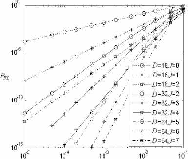
The simulation of P FA and P FL with different ASM code models and J are shown in Fig.8 and Fig.9.
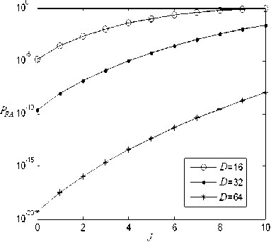
Figure 8. P FA with different ASM code models and J
From Fig.8 we can get that the value of P FA becomes large along with the increasing value of J and becomes small along with the increasing value of L ASM . From Fig.9 we can get that the value of P FL becomes large along with the increasing value of BER and becomes small along with the increasing value of J . So we can get the optimum values of L ASM and J as Table IV.
BER
Figure 9. P FL with different ASM code models and J
TABLE IV.
THE OPTIMUM VALUES OF L ASM AND J
|
L ASM (bits) |
J (bits) |
|
16 |
1 |
|
32 |
3 |
|
64 |
7 |
Setting a is the times for checking the ASM successfully, the probability of false sync P FS can be defined as
P FS = (1 - (1 - P FA ) L frame /2) P FaA - 1
Setting L frame =512 bytes and the value of J as the Table IV, P FS can be gotten as Table V.
TABLE V.
THE PROBABILITY OF FALSE SYNC
|
L ASM (bits) |
a (bits) |
|||
|
1 |
2 |
3 |
4 |
|
|
16 |
2.0 x 10⁻⁴ |
5.9 x 10⁻⁸ |
1.1 x 10⁻¹¹ |
3.0 x 10⁻¹⁵ |
|
32 |
6.7 x 10⁻⁹ |
8.5 x 10⁻¹⁵ |
1.1 x 10⁻²⁰ |
1.4 x 10⁻²⁶ |
|
64 |
6.0 x 10⁻¹⁸ |
2.3 x 10⁻²⁸ |
8.7 x 10-39 |
3.3 x 10-49 |
From (16) and Table V, we can get if the value of J is
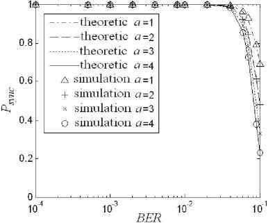
Figure 12. P sync with different a and L ASM =64bits
appropriate, PFA and PFS can be ignored. So, Psync can be defined as
P = (1 - P fl )a sync (1 - BER ) LFLM
The relations of P sync with different a and ASM code models are shown in Fig.10, Fig.11 and Fig.12.
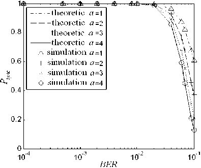
Figure 10. P sync with different a and L ASM =16bits
From Fig.10, Fig.11 and Fig.12, we can see that the simulation results are close to the theoretic results. So the reliability of (19) is proved.
Consequently, the parameters of AOS frame sync can be get as Table VI. Hereinto, the effect of frame sync is best at L ASM =64 bits, J =7bits and a =1bits.
The relation of channel SNR to BER are given as follows
BER = erfc (V SNR ) / 2 (20)
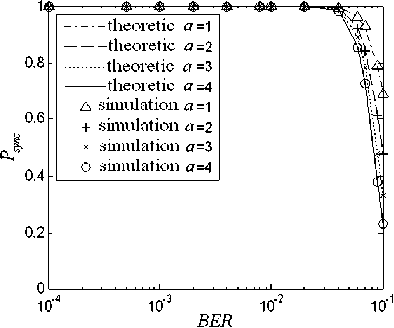
Figure 11. P sync with different a and L ASM =32bits
Then
P n c = (1 — Pfl ) a = (1 — Pfl ) a sync (1 - BER) LFLM (1 - erfc (V SNR )/2) LFLM
P success _ frame is given as
P success_fr ame P sync (1 p exp( q * SNR )) (22)
Setting E up R modulation R = k , T effective is given as
TABLE VI.
THE PARAMETERS OF AOS FRAME SYNC
|
ber |
L ASM |
J |
a |
|
ber < 10-4 |
16 |
1 |
> 4 |
|
10-2 < ber <10 —4 |
32 |
3 |
2or3 |
|
10-2
|
64 |
7 |
1 |
T effective = k ( L frame - L frame_c )(1 - ( p exp( - q ⋅ SNR )) Kmax + 1)( erfc ( 2 SNR )) LFLM
R ( J Ci (1-erfc( SNR))8LASM-i(erfc( SNR))i)a code ∑i 0 8LASM 2 2 (23)
⋅ ( L frame + L ASM )(1 - erfc ( SNR )/2) LFLM
-
F. Design of switch thresholds of cross layer system
The AOS cross layer system is simulated with following presumptions: L ASM =64bits, J =7bits, a =1bits, K max =1, k =1 and other parameters as above paragraphs. The simulation of T effective with different models is shown in Fig.13.
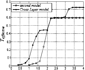
Figure 13. T effective with different models
From Fig.13 we can get the switch thresholds of SNR as Table VII. Here the cross layer scheme is proposed to maximize throughput by suitably determining discrete adaptive frame length L frame_ada based on different ranges of SNR . When SNR <1.5, the communications will be stopped because of too low T effective .
TABLE VII.
THE THRESHOLD OF AOS CROSS LAYER SYSTEM
|
model |
SNR threshold(dB) |
|
1 |
1.80 |
|
2 |
2.01 |
|
3 |
2.98 |
Fig. 13 shows the effective throughput rate of AOS cross layer scheme. So if channel SNR change, the throughput rate can be improved effectively by the proposed scheme compared with three fixed schemes, and the switch frequency of cross layer system is not high. The scheme is simple and need not change the frame length and code rate frequently, so the stability of the AOS and the reliability of data transmission can be guaranteed. So it is more suitable for practical data transmission.
-
VI. C ONCLUSIONS
An AOS cross layer scheme uses appropriate packet release time, frame length, code rate and sync parameter for the throughput rate improvement is presented in this paper. First of all, an effective throughput rate formula of AOS has been proposed, from which we know that the effective throughput is mainly affected by packet release time, frame length, coding and channel SNR. So a cross layer scheme controlling these parameters of different layers based on the ranges of SNR is provided for maximizing the effective throughput rate, which needn’t modify the AOS protocol too much. Simulation results show that compared with fixed transmission scheme, the proposed scheme can improve the AOS throughput rate effectively. Using the presented result, AOS protocol designers can verify and optimize their designs which provide a reference to the future application of space missions. This research does not consider the probability of modulation to AOS effective throughput rate. Further research is needed to support the performance analysis of more complicated communications. In addition, it was proven that the proposed AOS cross layer scheme provides an effective alternative to achieve high throughput under AWGN. The performance of the proposed AOS cross layer scheme in fading condition is future work.
References Cross Layer Transmission for AOS Packet Service
- Bi Mingxue, Pan Chengsheng, Wang Hongxia, and Tian Ye. “Study on Throughput for AOS Packet Service and Channel Adaptive Strategy,” IEEE, pp. 30–34, February 2009.
- Mihaela van der Schaar, Santhana Krishnamachari, Sunghyun Choi, et al.. “Adaptive cross-layer protection strategies for robust scalable video transmission over 802.11 WLANS,” IEEE J. on Select., Area. Commun., vol.21, pp. 1752-1763, 2009.
- Dai L, Letaief K B. “Throughput maximization of adhoc wireless networks using adaptive ooperative diversity and truncated ARQ [DB/OL],” http:// hdl. handle. net/ 1783. 1/ 2252, 2007/ 2008.
- G. Aniba and S. Aissa. “Adaptive scheduling for MIMO wireless networks: Cross-layer approach and application to HSDPA,” IEEE Trans. Wireless Commun., vol.6, pp. 259-268, January 2007.
- T. Keller. “Dynamic adaptation of IEEE 802.11b frame length for improving system performance,” 15th International Coneremnce on Microwaves, Radar and Wireless Communications, vol. 3, pp.1032−1035, Chicago, USA, May 2004.
- Yong Xi, et al, “Rate Adaptation Transmission Scheme for IEEE802.11 WLAN,” Journal of Communication and Computer, vol.3, pp. 70−73, 2006.
- Y. Nagai, et al, “Implementation of 324Mbps WLAN equipment with MAC frame aggregation for high MAC-SAP throughput,” the 3rd IEEE CCNC, Las Vegas, 2006.
- S. Z. Q. Liu and G. B. Giannakis. “Cross-layer combining of adaptive modulation and coding with truncated ARQ over nireless links,” IEEE Trans. Wireless Commun., vol.3, pp. 1746-1755, Sept. 2004.
- Low Density Parity Check Codes for Use in Near_earth and Deep Space Applications[S]. Research and Development for Space Data System Standards, CCSDS 131.1-O-2 Orange Book, Issue 2. Washington, D.C.: CCSDS, September 2007.
- TM Synchronization and Channel Coding[S]. Recommendation for Space Data System Standards, CCSDS 131.0-B-1 Blue Book, Issue 1. Washington, D.C.: CCSDS, September 2003.
- AOS Space Data Link Protocol[S], CCSDS 732.0-B-2 Blue Book, Consultative Committee for Space Data System, July, 2006
