Декаметровые радары ИСЗФ СО РАН

Автор: Бернгардт О.И., Куркин В.И., Кушнарев Д.С., Гркович К.В., Федоров Р.Р., Орлов А.И., Харченко В.В.
Журнал: Солнечно-земная физика @solnechno-zemnaya-fizika
Статья в выпуске: 2 т.6, 2020 года.
Бесплатный доступ
В рамках проекта «Национальный гелиогеофизический комплекс Российской академии наук» планируется создание нескольких когерентных декаметровых радаров. Однако в Институте солнечно-земной физики (ИСЗФ) СО РАН работы по созданию когерентных декаметровых радаров проводились задолго до начала финансирования этого проекта. Это позволило получить опыт эксплуатации подобных радаров, выявить технологические проблемы, которые желательно решить при создании отечественных радаров, и разработать проект радаров, имеющих более широкие возможности по диагностике ионосферы по сравнению с существующими аналогичными радарами. В работе представлено описание радара EKB ИСЗФ СО РАН, рассмотрены его технические недостатки и предложена структура нового радара системы СЕКИРА. Приведены результаты макетирования элементов радара СЕКИРА, продемонстрировавшие возможность его реализации. Обсуждаются потенциальные возможности использования радара в задачах исследования ионосферы на территории Российской Федерации, в том числе в высокоширотных областях.
Декаметровый радар, секира, ионосфера, обратное рассеяние
Короткий адрес: https://sciup.org/142224300
IDR: 142224300 | УДК: 621.396.967, | DOI: 10.12737/szf-62202006
ISTP SB RAS decameter radars
Under the project National Heliogeophysical Complex of the Russian Academy of Sciences, it is planned to create several coherent decameter radars. ISTP SB RAS developed a network of coherent decameter radars well before the start of financing this project. This has provided extensive experience in operating such radars, has enabled us to identify their technological problems, which should be solved when creating radars of own design, and to develop a project of radars with broader capabilities for diagnostics of the ionosphere as compared to existing radars of similar types. The paper analyzes the existing EKB ISTP SB RAS radar, reviews its technological problems, and proposes the structure of a new radar of SECIRA type. We report the results of prototyping of elements of the SECIRA radar, which demonstrate the possibility of its implementation. We discuss the potential applicability of the radar to ionospheric studies on the territory of the Russian Federation, in particular in high-latitude regions.
Текст научной статьи Декаметровые радары ИСЗФ СО РАН
Study of space weather effects in Earth's magnetosphere, ionosphere, and atmosphere is one of the main tasks of solar-terrestrial physics. At present, one of the most effective instruments for research in this direction is the international system SuperDARN (Super Dual Auroral Radar Network) — the network of decameter (shortwave) radars that cover high-latitude regions and a part of mid-latitude regions in the Northern and Southern hemispheres. Through joint analysis of parameters of scattered signals, SuperDARN allows us both to obtain a global picture of plasma convection in the high-latitude ionosphere, which is a key indicator of its interaction with the magnetosphere, and to study the dynamics of irregularities of different scales in the ionosphere and upper atmosphere at high spatial-temporal resolution. Over the past 12 years, the number of radars in this network has more than doubled, reaching 35. Many countries (USA, Canada, UK, France, Italy, Japan, Australia, South Africa, China, Norway) have been deeply involved in the ionospheric research in polar and subpolar latitudes of both hemispheres and have intensively developed the radar network. At the same time, without active participation of Russia whose area covers the longitudinal sector of ~100°, it is rather difficult to reconstruct the system of ionospheric plasma convection in Northern Hemisphere with reasonable accuracy and to predict the development of disturbances in the upper atmosphere during periods of severe space weather.
The development of the Russian network of coherent decameter radars will effectively complement the existing SuperDARN radar network and ensure equal participation of Russian scientists in the international cooperation of the countries participating in SuperDARN.
Solving problems of monitoring ionospheric disturbances affecting the operation of global positioning, communication, and radar systems on the entire territory of Russia with high time resolution using a relatively small number of facilities determines the practical significance of such radars. Studies are planned to be conducted under both international and Russian projects and programs in several directions. Among these are:
-
• reconstruction of ionospheric convection at high latitudes of the Russian Federation and elaboration of the full ionospheric convection in cooperation with SuperDARN radars;
-
• study of subauroral polarization streams (SAPS) and subauroral ion drifts (SAID), in particular in the integration with the existing network of instruments for optical and ionospheric observations, as well as with satellite measurements;
-
• study of mid- and high-latitude ionospheric irregularities of small, medium, and large scales and their relationship with space weather and influence from bellow — from the neutral atmosphere and the lithosphere, in particular in the integration with the existing network of instruments for seismic and ionospheric observations, as well as with satellite measurements;
This is an open access article under the CC BY-NC-ND license
-
• study of the magnetosphere-ionosphere coupling and magnetohydrodynamic waves, in particular in the integration with the network of instruments for groundbased magnetic observations and with satellite measurements;
-
• study of artificial disturbances in the ionosphere generated by high- and mid-latitude heating facilities;
-
• study of the dynamics of the lower ionosphere from observations of radio wave absorption in the D and E layers, in particular in the integration with the riometer network;
-
• study of processes in the neutral atmosphere from meteor observations, in particular in the integration with the existing network of optical instruments and meteor radars.
Under the project National Heliogeophysical Complex of the Russian Academy of Sciences (NHC RAS), we plan to develop several coherent decameter radars. The Institute of Solar-Terrestrial Physics SB RAS (ISTP SB RAS) made efforts to develop coherent decameter radars well before the start of financing this project. This has provided extensive experience in operating such radars, has allowed us to identify technical problems, which should be solved when creating national radars, to develop a project of radars having broader capabilities for diagnosing the ionosphere than the existing analogous radars.
SCIENTIFIC GOALS AND OBJECTIVES OF THE COHERENT RADAR NETWORK
The main mechanisms of the formation of a scattered signal detected by such radars are: scattering by field-aligned ionospheric irregularities of the E and F layers, scattering by the earth and water surfaces detected due to ionospheric refraction, scattering by ionized meteor trails at heights of the D and E layers, mesospheric echo.
Large- and medium-scale auroral plasma convection is one of the important processes in the study of the magnetosphere-ionosphere coupling. The study of the magnetosphere-ionosphere coupling is the main task accomplished with SuperDARN radars. It is based on the study of the ionospheric convection by analyzing scattering by small-scale irregularities of the F layer. The occurrence of such irregularities may be due to natural causes such as geomagnetic storms and substorms and due to the operation of heating facilities, which form a layer of such irregularities in a small region over a heater [Robinson et al., 2006]. The drift velocity of the irregularities at these heights is generally determined by the motion of particles in crossed electric and magnetic fields. Its analysis allows us to reconstruct the direction and amplitude of the electric field, which makes it possible to study processes in Earth's magnetosphere, examining the projection of the magnetosphere on high-latitude regions of the ionosphere along magnetic field lines. Finding the full vector of the electric field requires us to determine the full velocity vector and accordingly to study irregularities in the same region, using several radars; hence the need for a dense network of such radars at high latitudes [Greenwald et al., 1995; Chisham et al., 2007] and its extension to middle [Nishitani et al., 2019] and equatorial [Chizurumoke et al., 2020] latitudes.
Another direction is to study the dynamics of large-scale ionospheric irregularities with characteristic scales of hundreds of kilometers. The methods are based on the study of propagation of radio waves in an inhomogeneous ionosphere upon scattering by the earth surface (oblique backscatter sounding). From variations in the group delay, mode content, and angles of arrival we may evaluate changes in ionospheric parameters at the reflection point and monitor large-scale irregularities generating variations in the position of the reflection point (points), including internal atmospheric waves [Oinats et al., 2016] . To date, a large number of sources of large-scale internal atmospheric waves in the upper atmosphere have been identified. Among these are a strong Joule heating in the high-latitude ionosphere associated with either substorms and enhanced electrojets or with enhanced ionospheric flows in cusp; earthquakes; passage of the solar terminator; launches of carrier rockets. Such waves propagating in the upper atmosphere generate traveling ionospheric disturbances (TIDs), which can be observed by radars. The Russian radars will facilitate search and experimental study of large-scale waves, which are important for the understanding of energy transfer processes in the magnetosphere—ionosphere—atmosphere—lithosphere system.
Methods of studying the neutral ionosphere rely on the study of the scattering by small-scale ionization irregularities formed by burning meteors. The drift velocity and lifetime of the irregularities at these heights are generally determined by dissipation and transfer processes, thus enabling us to estimate the neutral wind speed at heights 80–100 km [Arnold et al., 2003] . Radars can observe radio wave scattering by meteor trails and on this basis we can measure the wind speed and direction in the mesosphere. Such measurements will significantly complement observations made at the meteor radar network and will stimulate studies of the structure of mesospheric winds at different spatial scales.
One of the methods for studying the lower ionosphere is to study the radio wave absorption in the D and E layers. The absorption can be measured by two methods: from the intensity of OBS signal [Chakraborty et al., 2018] and from the level of noise during periods without radar radiation [Berngardt et al., 2018; Bland et al., 2018] . In this case, to increase the validity of the method it is desirable to measure the absorption at several frequencies simultaneously [Berngardt et al., 2019a]. Study and prediction of ionospheric absorption are important practical tasks because the absorption significantly affects amplitudes and quality of reception of signals from radio facilities and radars. The radar ionospheric absorption diagnostics significantly supplements high-latitude riometric observations.
Another important line of research is the study of the so-called magnetohydrodynamic waves in the magnetosphere from coherent radar data. Mid-latitude radars can detect and identify such waves, which is difficult to realize with high-latitude radars. Due to high temporal resolution of the radars and the wide spatial coverage it is possible to conduct a detailed spatiotemporal analysis of such waves and to identify physical mechanisms responsible for their generation and dynamics [Chelpanov et al., 2018; Mager et al., 2019], which are difficult to examine using other, both ground-based and space-based facilities.
High sensitivity of coherent radars to various space weather effects defines the main applied problems of the network of such radars:
-
• monitoring of ionospheric disturbances that significantly affect the operation of communication, navigation, radar, and other technological systems on the territory of Russia;
-
• monitoring of radio wave propagation conditions in radar field of view, which provides the basis for effective prediction of radio wave absorption and propagation conditions including optimum frequencies in HF radio channels under different geophysical conditions;
-
• study and monitoring of processes in the magnetosphere—ionosphere—atmosphere—lithosphere system, which form the basis for the prediction of disturbances that affect the functionality of various radio aids and technological systems.
HARDWARE AND SOFTWARE OF SUPERDARN RADARS
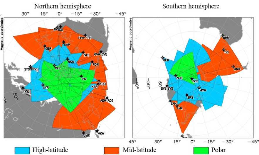
The network of coherent decameter SuperDARN radars [Greenwald et al., 1995; Chisham et al., 2007; Nishitani et al., 2019] and of analogous radars [Berngardt et al., 2015a] is one of the most effective modern ground-based instruments for studying the magnetosphere-ionosphere coupling and for monitoring the upper atmosphere in a large spatial region. The SuperDARN radar system currently includes more than 35 radars, and their number is constantly increasing. Loca- tion and fields of view of the radars are shown in Figure 1.
SuperDARN radars are instruments with analogous hardware and software. The radar is a monostatic instrument with a field of view of ~50° and a maximum operation range 3500–4500 km. This provides a spatial coverage of the order of 1 million sq. km. The radars operate in a frequency band 8–20 MHz with the mean radiated power of ~600 W, which allows us to use them in the continuous monitoring mode. The radar field of view is divided into a fixed number of directions (beams), the total number of which is usually from 16 to 24. Width of one beam is from 3° to 6° depending on the operating frequency. Spatial resolution of the radar ranges from 15 to 45 km, temporal resolution in a regular operating mode is ~1–2 min.
A coherent radar transmits a radio signal of a special shape, which propagates in the ionosphere and is scattered by irregularities occurring in its trajectory. A part of the transmitted signal power comes back to the place of transmission as a scattered signal and is received by the radar. The shape of the transmitted radio signal and the processing technique provide good spatial (accuracy of ranging to irregularities) and spectral (accuracy of determining the velocity of irregularities) resolution. Backscattering is the most intense for irregularities with scales of about half-wavelength along the line of sight, therefore such coherent radars are sensitive to plasma irregularities with characteristic scales of several tens of meters. The difference between frequencies of transmitted and received signals characterizes the velocity of irregularities at heights 150–450 km in crossed ionospheric electric and geomagnetic fields. While the theory of the formation and growth of such irregularities is currently still under development, experimental studies show close agreement between this model and the results obtained with coherent radars.
It should be noted that the coherent echo from ionospheric irregularities can be observed with SuperDARN radars only under certain (aspect) conditions of radio wave propagation with respect to the geomagnetic field. Such conditions for propagation of short radio waves are well satisfied in polar and subpolar regions, determining in turn the great practical significance of SuperDARN for studies of high-latitude ionospheric effects. For their functioning, the radars use multipulse aperiodic sequences of short pulses. The use of multipulse sequences allows simultaneous improvement in spatial and spectral resolution of the radar [Farley, 1972] .
For a SuperDARN radar the duration of the traditional 7-pulse sounding sequence is ~70 ms with a repetition period of ~100 ms [Chisham et al., 2007] .
The traditional method of processing a received signal at these radars is the calculation of its autocorrelation matrices and averaged complex-valued autocorrelation functions (ACFs). ACFs are approximated by model functions to estimate the scattered power, line-of-sight Doppler velocity, and signal spectrum width as a function of range from radar. The radar software provides data of three levels of detail: quadrature signal components (IQdat), averaged signal correlation functions (RawACF), and processed data (FitACF) [RST, 2019] .
EKB ISTP SB RAS RADAR
The first Russian radar similar to SuperDARN radars has been deployed by ISTP SB RAS together with the Institute of Geophysics UB RAS on the territory of the Geophysical Observatory Arti (the village of Arti, the Sverdlovsk Region, 56.5° N, 58.5° E). Its transceiver equipment, which is a CUTLASS-type radar [Lester et al., 2004] , was developed at the University of Leicester (UK) and purchased with funding from SB RAS. The phased antenna array (PA) of the radar features two linear PA standard for SuperDARN radars — 16 antennas in the receiving-transmitting array and 4 antennas in the receiving one. Geometry of the radar and its general layout are shown in Figure 2.
Since December 2012, the radar has operated in the regular monitoring mode. Using data obtained with the radar, we have carried out numerous experiments, in- cluding long-term ones: studies of magnetospheric VLF oscillations [Mager et al., 2015; Chelpanov et al., 2018], internal acoustic waves [Oinats et al., 2016], unique observations of ionospheric effects associated with the impact of the Chelyabinsk meteorite [Berngardt et al., 2015b], the first regular observations of the level of shortwave noise during solar flares [Berngardt et al., 2018, 2019a]. In addition, we performed the first experiments with the EKB ISTP SB RAS radar in a bistatic mode [Berngardt et al., 2015c], developed improved sounding sequences [Berngardt et al., 2015d], and derived radar equations for pulsed radars of this type [Berngardt et al., 2016], developed effective methods of identifying signals scattered by the earth surface [Lavygin et al., 2020].
Technological drawbacks of the EKB radar and ways to overcome them
Experience of the long-term operation of the EKB ISTP SB RAS radar has revealed major technological drawbacks that complicate the use of the radar for solving modern research problems.
Identification of signal types
The irregularities the scattering by which generates a received radar signal are different, therefore one of the main problems in interpreting data is the problem of distinguishing signals scattered, e.g., by the earth surface and the ionosphere. Currently there are two main approaches to the identification of such signals: from spectral characteristics obtained by averaging [Blanchard et al., 2009; Ribeiro et al., 2011] and from the analysis of the full form of scattered signals before their averaging [Lavygin et al., 2020] . Experiments have shown that the analysis of the full form of scattered signals is more efficient [Lavygin et al., 2020] , but the rate of digitization of received signals needs to be significantly increased, which cannot be done with the currently available equipment. Thus, an important technical problem to be solved is the replacement of the analog receiver part of the EKB radar with digital receivers with a high rate of digitization.
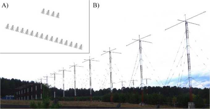
Figure 2. The EKB ISTP SB RAS radar: a — the phased antenna array; b — a general layout of the radar
Spatial, temporal, and spectral resolution
In a shortwave band, problems also arise when studying the dynamics and particularly velocities of ionospheric irregularities. The typical velocities of ionospheric irregularities are much lower than the sound speed at ionospheric heights — of the order of tens and hundreds of meters per second, so it is necessary to measure Doppler shifts up to 1 hertz at least. The use of simple radio pulses leads to the fact that the spatial resolution of the radar becomes comparable with the characteristic scales of the ionosphere.
Spatial resolution can be increased without loss of spectral resolution by using complex signals with specially selected properties and methods of processing received signals, which can simultaneously provide high spatial and spectral resolution. The complex signals are generally applied which represent multipulse sequences [Farley, 1972] . In regular measurements with SuperDARN radars, sequences of several types are currently used: standard 7-pulse [Barthes et al., 1998] , 8-pulse katscan [Ribeiro et al., 2013] , and 13-pulse [Greenwald et al., 2008] . The latest radars can use aperiodic sequences [Spaleta et al., 2008] .
As shown by a preliminary analysis, the characteristic lifetime of ionospheric irregularities generating backscatter is not more than 250 ms, whereas the lifetime of irregularities affecting the shape of signals scattered by the earth surface is usually longer [Lavygin et al., 2020] . The main characteristics of the signals providing geophysical data are the Doppler frequency shift and spectral signal width. The accuracy of determination of these parameters depends on the spectral resolution of the method not always sufficient for existing sounding sequences. The situation can be improved if we apply sequences consisting of a larger number of pulses. Specifically, the use of longer sequences at the EKB ISTP SB RAS decameter radar allows us to significantly improve spectral resolution of the method [Berngardt et al., 2015d] . Despite the development and launch of new 10-pulse sequences at the EKB radar in October 2014 [Berngardt et al., 2015d] , which ensure high spectral resolution of measurements, and the development of more complex and longer sequences from Golomb rulers, spectral resolution often remains inadequate or it takes too much time to accumulate signals. Thus, most new longer sounding sequences we have developed can be adopted only after upgrading the transceiver equipment of the radar.
In addition, potential of the radar (power, range, and spatial resolution) can be considerably increased by using phase-manipulated pulses, but this technique cannot be implemented with the radar equipment at present either and needs modernization.
Consideration of ionospheric parameters and spatial reference of observations
Due to peculiarities of the frequency band of such radars, the ionospheric refraction has a pronounced effect on the signal path and changes radio wave propagation trajectory and delay of the received signal. The ra- dio wave propagation path affects the accuracy of both identification of scattered signal type and determination of parameters of ionospheric irregularities — their velocity, height, and geographic coordinates. Determination of signal parameters provides the basis for the solution of practical problems, in particular for the use of coherent radars to monitor ionospheric conditions
Consideration of ionospheric parameters is based on measurements of the vertical-latitudinal-longitudinal electron density distribution. Correct consideration allows us both to provide the geographical reference of measurements and to improve the accuracy of the determination of spectral parameters of the irregularities. Currently, the main approaches to solving this problem are the use of ionospheric models corrected in real time according to the data from various instruments [Lar-quier et al., 2013] and the use of multifrequency observations [Ponomarenko et al., 2009; Gillies et al., 2011] . One of the possible solutions of this problem is to use the radar for diagnosing parameters of the background ionosphere. The existing equipment of the radar designed to transmit short pulses precludes, however, the use of the radar in the ionosonde mode with a high frequency sweep rate. Implementing this mode requires substantial hardware modernization of the radar involving an extension of the frequency band (5–25 MHz) and the use of more complex antennas providing radar operation in this mode, as well as other transmitters.
Calibration of elevation angle observations
One of the main methods of refining the radio signal propagation path is elevation observation. Because of the wavelength comparable to the distance from antenna to the earth surface, temperature variations in characteristics of the earth surface, and dynamics of analog parts of transceiver circuits for elevation observations, phase characteristics of antenna systems require regular calibration [Chisham, 2018; Ponomarenko et al., 2018] , preferably automatic. At present, in SuperDARN radars the main calibration methods are calibration by position of the signal scattered by the earth surface [Ponomarenko et al., 2015] , the signal scattered by the E layer [Ponomarenko et al., 2018] , and the signal scattered by meteor trails [Chisham, Freeman, 2013; Chisham, 2018; Berngardt et al., 2019b] .
Nevertheless, the PA structure of the EKB radar precludes precise elevation observations — owing to the large distance between the main and interferometric arrays there appears an uncertainty 2π n in measuring the phase, which significantly complicates the interpretation of the observations. An obvious solution is to change the PA shape with corresponding modernization of the receiving equipment and phasing system of the radar.
Implementation of bistatic sounding scheme
At present, SuperDARN radar systems operate in the bistatic mode in a narrow sense — each radar operates independently, and ionospheric parameters are identified from the processed data acquired by the radar network [Greenwald et al., 1995; Chisham et al., 2007;
Nishitani et al., 2019]. The first long observations in the bistatic mode in a broad sense with such radars have been made together with the EKB radar and the radio telescope UTR2 (Ukraine) [Berngardt et al., 2015c] . It has been shown that the existing equipment and power allow the operation in the mode when one radar serves as a transmitter for another. This operation mode allows us to expand regions in which it is possible to determine ionospheric parameters and obtain additional data to refine characteristics of ionospheric irregularities. It is therefore obvious that the equipment requires modernization, which will enable all radars of the Russian network to operate in a synchronous mode.
NEXT-GENERATION COHERENT RADARS
The project of radars of the SECIRA system (network of coherent ionospheric radars) has been developed at ISTP SB RAS to solve the technical problems found during operation of the EKB ISTP SB RAS radar and to greatly extend the capability of the network of Russian coherent decameter radars created under the project National Heliogeophysical Complex of the Russian Academy of Sciences (NHC RAS). The radar is based on fully digital generation and receiving of signals, which is currently the major approach in developing new radars [Bristow, 2019] .
Unlike PA of the EKB and SuperDARN radars, PA of the SECIRA radar is T-shaped and consists of 16 transmitting/receiving and 8 receiving antennas arranged in two perpendicular linear phased arrays. The distance between antennas coincides with distances in PhAA of SuperDARN radars (~15 m). The geometry of arrangement of receiving antennas allows us to minimize the problems associated with the phase uncertainty of the received signal, as well as to consistently identify signals coming from the back lobe. Thus, the radar field of view is doubled and takes the form of two symmetrical sectors with an aperture of 50° each. Antennas (linear size of no more than 15 m) should be wideband (5–25 MHz) and weakly influence each other. The maximum radiation power of each antenna is 1 kW.
The layout of phased antenna array (PA), and the block-diagram of the transmitting part of the radar are given in Figure 3, a and b respectively.
Since the receiving antenna array is perpendicular to the transmitting one, the elevation angle of received signal is more difficult to identify than with the standard geometry of PA (two parallel linear arrays) of SuperDARN radars. This problem is suggested to be solved in a digital form, which requires the use of 24 independent synchronized receivers, implemented as a unit of ana-log-to-digital converters (ADCs), and a multi-channel system for digital signal processing, which receives radio signals at a carrier frequency (with a bandwidth greater than the sounding signal frequency). The unit of protection of radio receiving equipment (RRE) protects the receiver circuits both from the influence of transmitters and from unexpected external interference such as thunderstorm activity. The unit of multichannel digital frequency synthesizers and digital-to-analog converters
(ADCs) with arbitrary setting of phase generates signals for each transmitting antenna and thereby form the antenna pattern of PA for transmission. Radio transmitting equipment (RTE) is output amplifiers providing a peak signal power to 700 W in a pulsed mode and to 300 W in a continuous mode as well as the required control of the signal level and antenna matching.
To increase the signal level from ADC to RTE, preamplifiers are used. The unit of control signals synchronizes the receiving and transmitting modes throughout the complex and generates other control signals. The general control over the complex, data processing and storage are performed by the signal processing center. Operation of the radars is synchronized via navigation satellites and the Internet, the absolute timing accuracy is up to 10 ns, which allows several SECIRA radars to work as one system and to use transmitted signals of each other.
The continuous operation will allow us to utilize the radar as an independent instrument for diagnostics of the background ionosphere by oblique sounding, specifically as a transmitting and/or receiving complex for the Russian network of chirp ionosondes [Ivanov et al., 2003] and transmitting complex for chirp ionosondedirection finders [Vertogradov et al., 2013] , which provides a significant increase in the coverage area of ionospheric observations and the integration with the equipment currently available in the Russian Federation for ionospheric observations.
To test elements of the SECIRA radar, we have developed a MAGW radar, which is intermediate between CUTLASS and SECIRA radars. The radar simultaneously exploits the equipment of CUTLASS type and the additional analog-to-digital equipment developed at ISTP SB RAS. MAGW has PA intermediate in its structure between PA of SuperDARN and SECIRA radars. The general layout of the MAGW radar and the form of its PA are shown in Figure 4.
Today, the MAGW radar is being tested, and the start of regular observations is being agreed upon. Characteristics of radars of all the types are compared in Table.
PROTOTYPE FOR THE SECIRA RADAR
To evaluate the performance of the SECIRA radar under the NHC RAS project, we have prototyped its individual units.
Prototyping of the digital unit of the radar
The digital unit of the radar is the most complex and most demanding of computing resources. The digital unit of the SECIRA radar was prototyped using the hardware unit manufactured by National Instruments. The NI PXIe 1085 chassis in use is structurally composed of an Intel PC-compatible computer and PXIe data bus. The PXIe data bus is a key element of the system combining all digital units of the radar. The data bus provides data transfer between the units at a rate up to 24 Gbit/s (to 8 Gbit/s between the two units). The data bus has 16 slots for field-programmable gate array (FPGA) boards and one slot for the module of distribution of synchronizing signals and generation of a clock signal.
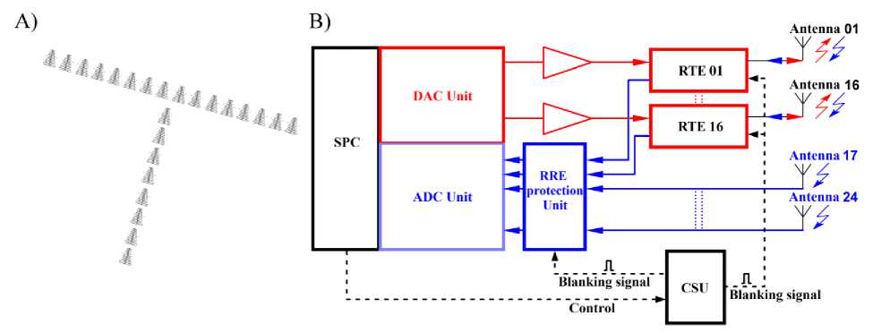
Figure 3. PA layout ( a ) and block-diagram of the SECIRA radar system ( b ): RRE is the radio receiving equipment; RTE is the radio transmitting equipment; CSU is the control signal unit; DAC unit is the digital-to-analog converter unit; ADC unit is the analog-to-digital converter unit; SPC is the signal processing center; blue lines indicate signal reception chains, red lines are signal transmission chains, black dashed lines mark driving signal chains.
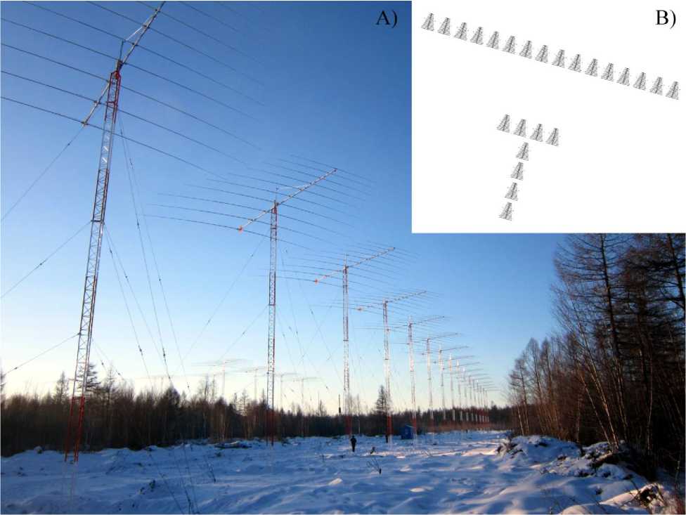
Figure 4. MAGW radar: a — the general view of PA; b — antenna layout in PA
Comparative characteristics of ISTP SB RAS radars
|
EKB |
MAGW (SECIRA v.1) |
SECIRA v. 2 |
|
|
Receivers and transmitters |
CUTLASS |
CUTLASS + selfengineered receivers |
self-engineered design |
|
Phased antenna array |
two parallel PA (16+ 4 antennas) |
two parallel and one perpendicular PA (16+4+4 antennas) |
two perpendicular PA (16+8 antennas) |
|
A zimuthal phasing system for transmission |
analog |
analog |
digital |
|
Azimuthal phasing system for receiving |
analog |
analog for 20 antennas and digital for 4 antennas |
digital for 24 antennas |
|
Receivers |
2 analog |
2 analog and 4 digital |
24 digital direct digitizing |
|
Frequency band |
8–20 MHz |
8–20 MHz |
5–25 MHz |
|
Accuracy of absolute synchronization |
100 µs |
100 µs |
10 ns |
|
Number of independent frequency channels |
2 |
2 |
2 |
|
Number of independent spatial channels for 1 frequency channel (transmission) |
1 |
1 |
16 |
|
Number of independent spatial channels for 1 frequency channel (receiving) |
2 |
6 |
24 |
|
Minimum discrete of sounding pulse |
100 µs |
100 µs |
10 µs |
|
Capability of intrapulse phase modulation |
— |
— |
+ |
|
Continuous signals |
— |
— |
+ |
|
Mean transmitter power in the pulse mode |
600 W |
600 W |
600 W |
|
Mean transmitter power in the continuous mode |
– |
– |
300 W |
|
Data storage format |
IQdat |
IQdat |
IQdat |
|
AP beamwidth |
3–6º |
3–6º |
3–12º |
|
Effective azimuthal field of view |
50º |
50º + 50º (back lobe) |
50º + 50º (back lobe) |
|
Uncertainty in determining the elevation angle |
high |
low |
low |
|
Degree of readiness for work |
has worked since 2012 |
deployed, underway |
under development |
A key difference between FPGA and processors and microcontrollers is in the absence of the predetermined circuit logic. These devices allow us to develop high-capacity hardware systems for digital signal processing. The general layout of the digital kernel of the system is presented in Figure 5.
The developed software of the radar consists of three main units — a signal generation and transmission unit, a recording unit of received signals, and a unit of the main control software. The kernel modules were programmed by constructing logical flowcharts in the graphical programming environment LabVIEW.
The simulation and testing have revealed that the developed software and hardware prototype of the digital unit of the SECIRA radar allows us to functionally duplicate the CUTLASS radar. In this case, the radar can work both with the MAGW radar array (Figure 4, b ) and with a new array of the SECIRA radar (Figure 3, a ). The prototype contains ~2/3 of hardware resources (logic blocks) of receiver boards and 1/2 of logic blocks of transmitter boards. The considerable store of FPGA resources enables further implementation and modernization of the remaining operation modes of the radar.
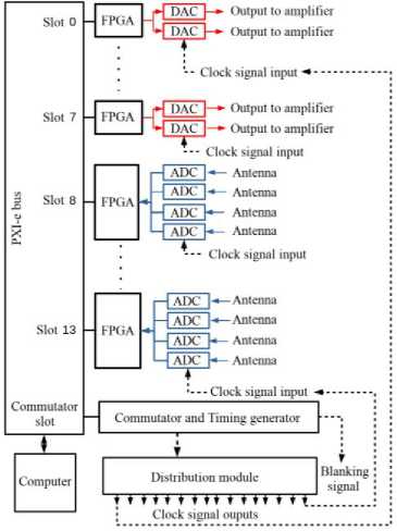
Figure 5. Flowchart of a digital part of the SECIRA prototype. Blue lines represent signal receiving circuits, red lines show signal transmission circuits, black strokes are control signal circuits
Prototyping of radar transmitters
The transmitting unit of the radar has been prototyped using RTE designed by the Omsk Branch of NPO Zavod Volna specifically for ISTP SB RAS. Each transmitter consists of a power output amplifier, an antenna-feeder monitoring system, a monitoring and control system in a single metal housing. RTE can operate in pulse and continuous modes. A transmitter provides a peak output power for the antenna-feeder system up to 700 W in the pulse mode, and a mean output power of ~ 200 W in the continuous mode. The transmitter has a system of on-line control of its temperature and the state of the antenna-feeder system with data transmission to the control computer.
Analog RTE circuits provide a 1.5–30 MHz bandwidth and have output filters for this frequency band. Power versus frequency in the two operating modes is shown in Figure 6.
As shown by the prototyping, these transmitters have satisfactory characteristics and can be used in SECIRA radars.
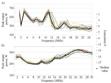
Figure 6. Transmitter output power in pulse ( a ) and continuous ( b ) modes as a function of frequency
Prototyping of radar antennas
The need for energy efficiency of the radar requires antennas well matched for the entire operating frequency band 5–25 MHz. To ensure a well matched and efficient (standing wave factor (SWF) <2.5 in the operating range) operation of the antenna array, antennas should be, on the one hand, sufficiently large and, on the other hand, weakly affect the adjacent antennas. We have created a prototype of the antenna (omega-log-periodic) satisfying these parameters. This is a log-periodic antenna whose dipoles are bent at an angle of ~60°. Such antenna geometry minimizes the interference of adjacent antennas even if they are closely spaced in PA.
The general layout of the antenna is given in Figure 7, a . The antenna was prototyped using the MMANA software. Figure 7, b shows the behavior of SWF as a function of frequency. We can see that the antenna is energy efficient and its SWF is not more than 2.5 in the operating frequency band of the radar. The prototyping has shown that the antenna system on the basis of this antenna can be used in SECIRA radars.
CONCLUSION
SuperDARN radars were originally developed to study convection in polar regions. Their long-term operation has, however, expanded the range of geophysical problems solving by the radars, at the same time identifying the problems arising from the use of such radars.
An important part of the radar is its antenna systems.
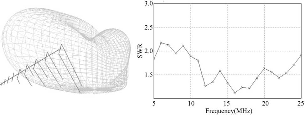
Figure 7. General layout of the antenna prototype and its antenna pattern ( a ), as well as its SWF as a function of frequency ( b )
The paper has defined the main areas of research at the network of coherent decameter radars SECIRA, developed by ISTP SB RAS under the NHC RAS project. We have set forth the prerequisites of the development of new-generation national radars and the full range of expected geophysical problems and modern approaches to their solution. We have described the structure of SECIRA radars and technical solutions used for designing them, demonstrated the differences between the new radars and SuperDARN radars. We have reported the results of prototyping of individual components of the SECIRA radar, which show that they can be applied to new-generation radars.
SECIRA radars along with the radars deployed by ISTP SB RAS before (Figure 8) should, first, expand the capabilities of Russian radars as compared to SuperDARN radars and, second, integrate effectively with the existing national and international networks of geophysical instruments. We plan to cover the RF territory by twin radars located in the Sverdlovsk (EKB, 56° N, 58° E), Irkutsk (IRK, 53° N, 105° E), and Magadan (MAG, 60° N, 150° E) regions and in the north of the Krasnoyarsk Region (NOR, 69° N, 88° E).
Deployment of the SECIRA radars will significantly improve the information content of basic and applied studies of ionospheric processes over the territory of the Russian Federation including high latitudes, in particular due to the integration of the SECIRA radar network with the existing Russian networks of instruments for ionospheric, optical, magnetic, and meteor observations.
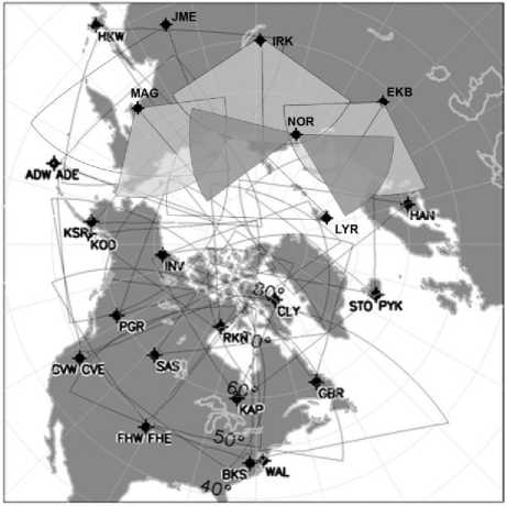
Figure 8. Expected fields of view of SECIRA radars deployed and planned. Contour lines show fields of view of SuperDARN radars
The high temporal resolution of the radars, the wide spatial coverage of each instrument, the development of new sounding and data analysis techniques allow us to reach the state-of-the-art level of research into the magnetosphere-ionosphere-atmosphere-lithosphere interaction and to solve problems in real time both of studying related phenomena and of their effective prediction.
Список литературы Декаметровые радары ИСЗФ СО РАН
- Arnold N.F., Cook P.A., Robinson T.R., Lester M., et al. Comparison of D-region Doppler drift winds measured by the SuperDARN Finland HF radar over an annual cycle using the Kiruna VHF meteor radar // Annales Geophysicae. 2003 V. 21, N 10. P. 2073-2082. DOI: 10.5194/angeo-21-2073-2003
- Barthes L., Andre D.A., Cerisier J.-C., Villain J.-P. Separation of multiple echoes using a high-resolution spectral analysis for SuperDARN HF radars // Radio Sci. 1998. V. 33, N 4. P. 1005-1017. DOI: 10.1029/98rs00714
- Berngardt O.I., Zolotukhina N.A., Oinats A.V. Observations of field-aligned ionospheric irregularities during quiet and disturbed conditions with EKB radar: First results // Earth, Planets and Space. 2015a. V. 67, N 1. P. 143. DOI: 10.1186/s40623-015-0302-3
- Berngardt O.I., Perevalova N.P., Dobrynina A.A., et al. Toward the azimuthal characteristics of ionospheric and seismic effects of "Chelyabinsk" meteorite fall according to the data from coherent radar, GPS, and seismic networks // J. Geophys. Res.: Space Phys. 2015b. V. 120, N 12. P. 10,754-10,771. DOI: 10.1002/2015JA021549
- Berngardt O.I., Kutelev K.A., Kurkin V.I., et al. Bistatic sounding of high-latitude ionospheric irregularities using a Decameter EKB Radar and an UTR-2 Radio Telescope: First results // Radiophysics and Quantum Electronics. 2015c. V. 58, N 6. P. 390-408. DOI: 10.1007/s11141-015-9614-1
- Berngardt O.I., Voronov A.L., Grkovich K.V. Optimal signals of Golomb ruler class for spectral measurements at EKB SuperDARN radar: Theory and experiment // Radio Sci. 2015d. V. 50, N 6. P. 486-500.
- DOI: 10.1002/2014RS005589
- Berngardt O.I., Kutelev K.A., Potekhin A.P. SuperDARN scalar radar equations // Radio Sci. 2016 V. 51, N 10. P. 1703-1724.
- DOI: 10.1002/2016rs006081
- Berngardt O.I., Ruohoniemi J.M., Nishitani N., et al. Attenuation of decameter wavelength sky noise during X-ray solar flares in 2013-2017 based on the observations of midlatitude HF radars // J. Atmos. Solar-Terr. Phys. 2018. V. 173. P. 1-13.
- DOI: 10.1016/j.jastp.2018.03.022
- Berngardt O.I., Ruohoniemi J.M., St-Maurice J.-P., et al. Global diagnostics of ionospheric absorption during X-ray solar flares based on 8- to 20-MHz noise measured by over-the-horizon radars // Space Weather. 2019a. V. 17, N 6. P. 907-924.
- DOI: 10.1029/2018SW002130
- Berngardt O.I., Fedorov R.R., Ponomarenko P., Grkovich K.V. Interferometric calibration and the first elevation observations at EKB ISTP SB RAS radar at 10-12 MHz // arXiv e-prints. 2019b. arXiv: 1912.05788 [physics.geo-ph].
- Blanchard G.T., Sundeen S., Baker K.B. Probabilistic identification of high-frequency radar backscatter from the ground and ionosphere based on spectral characteristics // Radio Sci. 2009. V. 44, N 5, RS5012.
- DOI: 10.1029/2009rs004141
- Bland E.C., Heino E., Kosch M.J., Partamies N. SuperDARN radar-derived HF radio attenuation during the September 2017 solar proton events // Space Weather. 2018. V. 16, iss. 10. P. 1455-1469.
- DOI: 10.1029/2018sw001916
- Bristow W.A. Application of RADAR imaging analysis to SuperDARN observations // Radio Sci. 2019. V. 54, N 7. P. 692-703.
- DOI: 10.1029/2019rs006851
- Chakraborty S., Ruohoniemi J.M., Baker J.B.H., Nishitani N. Characterization of short-wave fadeout seen in daytime SuperDARN ground scatter observations // Radio Sci. 2018. V. 53, N 4. P. 472-484.
- DOI: 10.1002/2017RS006488
- Chelpanov M.A., Mager O.V., Mager P.N., et al. Properties of frequency distribution of Pc5-range pulsations observed with the Ekaterinburg decameter radar in the nightside ionosphere // J. Atmos. Solar-Terr. Phys. 2018. V. 167. P. 177-183.
- DOI: 10.1016/j.jastp.2017.12.002
- Chisham G. Calibrating SuperDARN interferometers using meteor backscatter // Radio Sci. 2018. V. 53, N 6. P. 761-774.
- DOI: 10.1029/2017RS006492
- Chisham G., Freeman M.P. A reassessment of SuperDARN meteor echoes from the upper mesosphere and lower thermosphere // J. Atmos. Solar-Terr. Phys. 2013. V. 102. P. 207-221.
- DOI: 10.1016/j.jastp.2013.05.018
- Chisham G., Lester M., Milan S.E., et al. A decade of the Super Dual Auroral Radar Network (SuperDARN): scientific achievements, new techniques andfuture directions // Surv. Geophys. 2007. N 28. P. 33-109.
- DOI: 10.1007/s10712-007-9017-8
- Chizurumoke М.M., Yeoman T.K., Wright D.M., et al. A ray tracing simulation of HF ionospheric radar performance at African equatorial latitudes // Radio Sci. 2020. V. 55, N 2, e2019RS006936.
- DOI: 10.1029/2019rs006936
- Farley D.T. Multiple-pulse incoherent-scatter correlation function measurements // Radio Sci. 1972. V. 7, N 6. P. 661-666.
- DOI: 10.1029/rs007i006p00661
- Gillies R.G., Hussey G.C., Sofko G.J., et al. Improvement of HF coherent radar line-of-sight velocities by estimating the refractive index in the scattering volume using radar frequency shifting // J. Geophys. Res. 2011. V. 116, A01302.
- DOI: 10.1029/2010JA016043
- Greenwald R.A., Baker K.B., Dudeney J.R., et al. DARN/SuperDARN: A global view of the dynamics of high-latitude convection // Space Sci. Rev. 1995 V. 71. P. 761-796.
- DOI: 10.1007/BF00751350
- Greenwald R.A., Oksavik K., Barnes R., et al. First radar measurements of ionospheric electric fields at sub-second temporal resolution // Geophys. Res. Lett. 2008. V. 35, N 3, L03111.
- DOI: 10.1029/2007gl032164
- Ivanov V.A., Kurkin V.I., Nosov V.E., et al. Chirp ionosonde and its application in the ionospheric research // Radiophys. and Quant. Electron. 2003. V. 46, N 11. P. 821-851. :RAQE.0000028576.51983.9c.
- DOI: 10.1023/B
- de Larquier S., Ponomarenko P., Ribeiro A.J., et al. On the spatial distribution of decameter-scale subauroral ionospheric irregularities observed by SuperDARN radars // J. Geophys. Res.: Space Phys. 2013. V. 118, N 8. P. 5244-5254.
- DOI: 10.1002/jgra.50475
- Lavygin I.A., Lebedev V.P., Grkovich K.V., Berngardt O.I.. Identifying ground scatter and ionospheric scatter signals by using their fine structure at Ekaterinburg Decametre Coherent Radar // IET Radar, Sonar & Navigation. 2020. V. 14, N 1. P. 167-176.
- DOI: 10.1049/iet-rsn.2019.0192
- Lester M., Chapman P., Cowley S.W.H., et al. Stereo CUTLASS - A new capability for the SuperDARN HF radars // Ann. Geophysicae. 2004. V. 22, N 2. P. 459-473.
- DOI: 10.5194/angeo-22-459-2004
- Mager P.N., Berngardt O.I., Klimushkin D.Yu., et al. First results of the high-resolution multibeam ULF wave experiment at the Ekaterinburg SuperDARN radar: Ionospheric signatures of coupled poloidal Alfv'en and drift-compressional modes // J. Atmos. Solar-Terr. Phys. 2015. V. 130-131. P. 112-126.
- DOI: 10.1016/j.jastp.2015.05.017
- Mager O.V., Chelpanov M.A., Mager P.N., et al. Conjugate ionosphere-magnetosphere observations of a sub-Alfvenic compressional intermediate-m wave: A case study using EKB radar and Van Allen probes // J. Geophys. Res.: Space Phys. 2019. V. 124, N 5. P. 3276-3290.
- DOI: 10.1029/2019JA026541
- Nishitani N., Ruohoniemi J.M., Lester M., et al. Review of the accomplishments of mid-latitude Super Dual Auroral Radar Network (SuperDARN) HF radars // Progress in Earth and Planet. Sci. 2019. V. 6, N 1. P. 27.
- DOI: 10.1186/s40645-019-0270-5
- Oinats A., Nishitani N., Ponomarenko P., et al. Statistical characteristics of medium-scale traveling ionospheric disturbances revealed from the Hokkaido East and Ekaterinburg HF radar data // Earth, Planets and Space. 2016. V. 68, N 1. P. 8.
- DOI: 10.1186/s40623-016-0390-8
- Ponomarenko P.V., St-Maurice J.-P., Waters C.L., et al. Refractive index effects on the scatter volume location and Doppler velocity estimates of ionospheric HF backscatter echoes // Ann. Geophys. 2009. V. 27. P. 4207-4219.
- DOI: 10.5194/angeo-27-4207-2009
- Ponomarenko P., Nishitani N., Oinats A.V., et al. Application of ground scatter returns for calibration of HF interferometry data // Earth, Planets and Space. 2015. V. 67, N 1. P. 138.
- DOI: 10.1186/s40623-015-0310-3
- Ponomarenko P.V., St-Maurice J.-P., McWilliams K.A. Calibrating HF radar elevation angle measurements using E layer backscatter echoes // Radio Sci. 2018. V. 53, N 11. P. 1438-1449.
- DOI: 10.1029/2018rs006638
- Ribeiro A.J., Ruohoniemi J.M., Baker J.B.H., et al. A new approach for identifying ionospheric backscatter in midlatitude SuperDARN HF radar observations // Radio Sci. 2011. V. 46, RS4011.
- DOI: 10.1029/2011RS004676
- Ribeiro A.J., Ruohoniemi J.M., Ponomarenko P.V., et al. A comparison of SuperDARN ACF fitting methods // Radio Sci. 2013.V. 48, N 3. P. 274-282.
- DOI: 10.1002/rds.20031
- Robinson T.R., McCrea I.W., van Eyken A.P., et al. First observations of SPEAR-induced artificial backscatter from CUTLASS and the EISCAT Svalbard radars // Ann. Geophys. 2006. V. 24, iss. 1. P. 291-309.
- DOI: 10.5194/angeo-24-291-2006
- RST - Radar Software Toolkit. 2019. URL: https://github.com/SuperDARN/rst (дата обращения 20 ноября 2019 г.).
- Spaleta J., Bristow W.A., Parris R.T., et al. Enhanced Line of Sight Velocity Analysis Using an Aperiodic Pulse Sequence on the Kodiak and King Salmon Radars // SuperDARN 2008 Workshop. 02-06 June 2008, Newcastle, Australia. 2008. URL: http://www.tiger.latrobe.edu.au/super-darn2008/procCD/presentations/1070.pdf (дата обращения 20 ноября 2019 г.).
- Vertogradov G.G., Uryadov V.P., Vertogradova E.G., et al. Chirp ionosonde-radiodirection finder as a new tool for studying the ionosphere and radio-wave propagation // Radiophys. and Quant. Electron. 2013. V. 56, N 5. P. 259-275.
- DOI: 10.1007/s11141-013-9431-3
- URL: vt.superdarn.org (дата обращения 20 ноября 2019 г.).
