Delay-sensitive Quality of Service Routing with Integrated Admission Control for Wireless Mesh Network

Author: Satish S. Bhojannawar, Shrinivas R. Managalwede, Carlos F. Cruzado
Journal: International Journal of Computer Network and Information Security @ijcnis
Article in issue: 6 vol.16, 2024.
Free access
Wireless mesh networks (WMNs) extend and improve broadband Internet connectivity for the end-users roaming around the edges of the wired network. Amid the explosive escalation of users sharing multimedia content over the Internet, the WMNs need to support the effective implementation of various multimedia applications. The multimedia applications require assured quality of service (QoS) to fulfill the user requirements. The QoS routing in WMNs needs to guarantee the QoS requirements of multimedia applications. Admission control (AC) is the primary traffic control mechanism used to provide QoS provisioning. AC admits a new flow only if the QoS requirements of already admitted flows are not violated, even after the admission of a new flow. We propose a new QoS routing protocol integrated with AC called Delay-Sensitive QoS Routing with integrated Admission Control (DSQRAC) to control the admission of delay-sensitive flows. A delay-aware cross-layer routing metric is used to find the feasible path. DSQRAC is implemented using ad-hoc on-demand distance vector (AODV) routing protocol, where a delay-sensitive controlled flooding mechanism is used to forward the route request packets. In the proposed work, we adjust/reassign the channels to aid the QoS routing to increase the likelihood of accepting a new flow. The simulation results show that the performance of the proposed QoS routing protocol is better than the existing schemes.
Wireless Mesh Network, QoS Routing, Admission Control, Channel Reassignment, Cross-layer
Short address: https://sciup.org/15019539
IDR: 15019539 | DOI: 10.5815/ijcnis.2024.06.02
Text of the scientific article Delay-sensitive Quality of Service Routing with Integrated Admission Control for Wireless Mesh Network
WMNs are self-organizing, self-healing networks that deliver Internet services across broad coverage areas [1]. WMNs extend and improve broadband Internet connectivity for end-users roaming around the edges of the wired network. Owing to the rapid growth in the use of different real-time multimedia applications, the WMNs must fulfill QoS requirements of such applications [2]. Due to fluctuating capacity of wireless links, multi-hop transmission, and wireless channel contention, the QoS provisioning over WMN is more challenging. The use of multi-radio nodes and multiple channels in the multi-radio multi-channel WMN (MRMC-WMN) alleviates network interference and increases network capacity. But the time-varying wireless environment and real-time multimedia application’s high demand for QoS repeatedly leaves the users unsatisfied with present network performance. So, the critical difficulties in developing the MRMC-WMN backbone is how to design relevant algorithms and protocols to fairly satisfy the QoS requirements of multimedia applications. Routing decisively contributes to the provision of QoS and improves the network performance. The routing protocol with QoS provisioning needs to employ a self-serving strategy to find an end-to-end routing path that meets the QoS demands of real-time multimedia applications. AC is the primary traffic control mechanism deployed to provide QoS provisioning [3]. AC accepts new flow only if sufficient network resources are available to fulfill the requirements of new and existing flows.
Here, we focus on end-to-end delay requirements of delay-sensitive multimedia applications such as live video streaming, voice over IP. These applications require a lower end-to-end delay to preserve their interactive and streaming characteristics [4]. For the delay-sensitive multimedia applications, we aim to discover a path with minimum end-to-end delay. For this, we propose a routing protocol called Delay-Sensitive QoS Routing with integrated Admission Control (DSQRAC), which is implemented using AODV [5] routing protocol. A delay-aware cross-layer routing metric is used to find the feasible path with minimum end-to-end delay. During route discovery, DSQRAC protocol uses route request (RREQ) packets to discover the path that satisfies the delay requirements of a new flow. The node forwards RREQ packets if it is able to fulfill the delay requirement. As the RREQ packets are forwarded only by the nodes that guarantee the required delay requirement, DSQRAC avoids the unnecessary flooding of RREQ packets and makes provision to save the possible network resources to be consumed by such RREQs. The availability of network resources affects the existence of a feasible path. The routing and channel assignment algorithms control the resource availability [6]. As part of route discovery, we adjust/reassign available network resources to increase the likelihood of finding a feasible path. The prime purpose is to maximize the flow acceptance rate through the interaction of routing and channel assignment. Hence, we propose a joint QoS routing and channel assignment with an integrated admission control scheme for WMNs
The rest of the paper is organized as follows. Section 2 describes the related work. Section 3 presents the system model and problem statement. DSQRAC routing protocol is presented in Section 4. In Section 5, we evaluate the performance of DSQRAC. Finally, Section 6 concludes the paper.
2. Related Works
QoS routing is a fundamental research problem in the WMNs. Many studies on QoS routing protocols have been proposed to satisfy end-to-end QoS requirements for real-time multimedia applications. Some protocols are with admission control, and some are without admission control. Here, we review the QoS routing with admission control.
The protocol proposed in [7] computes the end-to-end delay. As a stream of dummy packets used for the end-to-end delay estimation, this protocol has significant control overhead and affects the network throughput. Since the protocol does not employ a bandwidth estimation mechanism at intermediate nodes, it cannot guarantee the delivery of all the packets of every admitted flow. The protocol takes more time for path discovery. The protocol proposed in [8] has a residual bandwidth-based distributed hop-by-hop AC solution. The interference is captured using the conflict graph. Authors have assumed fixed channel capacity. Under the local maximum clique constraints, each node uses more transmission power to communicate its flow information; this extra power causes significant overhead and consumes a substantial part of the available bandwidth. The protocol proposed in [9] uses a dual threshold-based approach, where nodes regularly share their traffic statistics and estimate their available bandwidth. It uses extended-range transmission to exchange messages. The protocol is not capable of coping with multi-rate nodes and could not account for the possibility of concurrent transmissions, resulting in an underestimation of the node’s available bandwidth. A joint QoS routing and centralized channel assignment protocol proposed in [10] uses with greedy approach to find a path. It uses an interference-based routing metric to find k paths. For each of the k paths, the feasibility in terms of available bandwidth is checked. If a path is infeasible, the channel assignment algorithm tries to remap the channels among nodes to make it a feasible path. The proposed group channel change procedure treats all violated links as out-of-path violated links and tries to reassign channels. The path discovery time is more and the entire process is more complex. The protocol proposed in [11] uses a distributed AC algorithm to discover two node-disjoint paths. As the protocol does not consider path stability, it subdues the performance of channel allocation mechanism. Protocol is not suitable for multichannel networks. The protocol assumes flow demands are stable and known well in advance. This presumption is unrealistic, and it doesn’t react to any network changes.
The multi-path routing protocol proposed in [12] classifies traffic into three groups and finds several high-quality paths. For load balancing and path reservation, it employs a feedback-based approach. The protocol assumes flow demands are stable and known well in advance and takes more time for path discovery. The protocol proposed in [13] uses interference-aware clique and cross-layer distributed AC protocol to support QoS in WMNs. Nodes share traffic statistics regularly and estimate their available bandwidth based on local maximal clique constraints. The AC technique only involves cluster heads and uses a feedback-based mechanism to control the congestion. Establishing a maximal clique in real-time is challenging, even for a small network, so the use of the maximum clique is quite complex. This protocol does not take into account link breakdown and dynamic channel assignment. The protocol proposed in [14] uses bandwidth estimation at each node along with delay-constrained admission control from multi-rate WMN. First, it estimates available bandwidth at each node. Then AC estimates the bandwidth to be consumed by flow and decides to admit the new flows. It also makes sure that delay requirements of real-time flows are satisfied. The protocol assumes static channel assignment and makes an effort to admit the flows on the assigned channels only. Energy-aware crosslayer-based protocol proposed in [15] uses a bandwidth-aware AC mechanism for allocating bandwidth to support different applications. It uses a cross-layer design to collect routing information such as node's available energy, node ID, congestion information from a different layer to build a shared database and shares its database to its neighbors. Based on the received details, it allocates bandwidth for flows. Due to a lot of information exchange, the proposed mechanism has a lot of control overhead. The queuing mechanism used may result in the starvation of non-real-time applications. The protocol proposed in [16] uses bandwidth and delay-aware routing-based AC integrated with a dynamic link schedule (LS). Whenever flows enter/exit, the network LS is updated. The AC decides to accept/reject a new flow based on the global network state information. Each gateway maintains scheduling matrices of the network and exchanges their schedule matrices to have up-to-date matrices. This AC mechanism with LS has a significant control overhead and has complex operations.
In all the existing protocols except [10], with available resources only, each protocol proposed in [7-9, 12-16] try to find a feasible path that satisfies the end-to-end requirements of flows. If they did not find a feasible path, none of the protocols makes an effort to adjust the network resources to increase the likelihood of finding a feasible path. The protocol in [14] tries to find k paths and investigate their feasibility, so it takes more time to find a feasible path. It uses a centralized algorithm and uses only interference-based routing metric. On the other hand, due to exchange of large amount of control information, the QoS routing protocols proposed in [7, 8, 13, 15, 16] with AC have lot of control overhead. The multipath routing protocols proposed in [11, 12] have out-of-order packet delivery. We need a QoS routing protocol with admission control that tries to adjust the network resources to increase the likelihood of finding a feasible path and also has simple operations with low complexity.
3. Problem Statement and System Model 3.1. Problem Statement
Here, we investigate the problem of enhancing network performance, assessed in terms of acceptance rate of delaysensitive flows. The new data flow i , QSD i = { s i , d i , e i , t i } arrives at any time t i with its end-to-end delay requirement e i . For new flow ‘ i ’, we need to discover a feasible path from source s i to destination d i . To assure the end-to-end QoS requirements, we need to estimate available resources on the end-to-end path. To fulfill the end-to-end delay requirement, estimated path delay should be smaller than the required delay ( e i ). An end-to-end path with lowest end-to-end delay results in a high throughput. The end-to-end delay is a total delay experienced at each hop on its source to destination path. Resource availability such as available bandwidth of link is the main factor that affects existence of feasible path. Routing scheme distributes traffic over network paths, while CA scheme assign channels based on traffic knowledge. The routing scheme determines how flows utilize the network bandwidth. The channel assignment scheme determines how much bandwidth is available on each link. If the routing scheme requires extra bandwidth on a link, the channel assignment scheme can furnish it by redistributing channels among competing links. So, to increase the likelihood of finding feasible paths, both routing and channel assignment need to be optimized together.
3.2. System Model
4. Delay-Sensitive QoS Routing with Integrated AC Routing Protocol
4.1. Overview of Proposed Protocol4.2. Delay-sensitive QoS Routing with Integrated AC Routing Protocol
We consider MRMC-WMN with the IEEE 802.11 DCF MAC protocol. Each router is assigned with a unique ID. Each router is equipped with R radio interfaces. WMN has C orthogonal channels. Our routing strategy is for wireless mesh backbone. Packets are forwarded via multi-hop packet forwarding over the mesh backbone routers. As part of initial configuration, we use interference-aware and network-connectivity-aware channel assignment scheme to assign orthogonal channels to radios of routers (nodes), such that the resulting wireless mesh backbone is highly connected with minimum co-channel interference. The node ‘i’ and ‘j’ have a common channel Ck between them. We consider ij network traffic between users connected to mesh routers and the gateway nodes. All flows enter network at random time and each flow has its end-to-end delay requirement.
We propose a cross-layer QoS routing protocol to discover the path to fulfill the end-to-end delay requirement of delay-sensitive multimedia applications. The protocol is implemented using AODV routing protocol. It uses AODV RREQ control packet based admission control mechanism to discover a path to destination. We use Interference, Traffic Load and Delay Aware (ITLDA) cross-layer routing metric proposed in [22] to estimate a delay of each link on path between source and destination. The one-hop delay is the sum of the transmission delay, average channel access (contention) delay, and queuing delay. The delay experienced at each hop should be carefully determined. The available bandwidth of the link determines the one-hop delay. Interference among different nodes affects the link’s available bandwidth. The intra-flow interference has an impact on the available bandwidth of in-path links, and inter-flow interference has an impact on the available bandwidth of out-of-path links. So, the available bandwidth of link (per-hop basis) under the influence of interference is to be estimated properly. In ITLDA, the available bandwidth of the link used for the one-hop delay calculation is estimated using logical and physical interference models. In AODV, the source node runs the route discovery process for a maximum of RREQ_RETRIES number of times [8]. During each attempt, the proposed DSQRAC protocol tries to discover a feasible path that satisfies the end-to-end delay.
Due to a lack of required resources, DSQRAC protocol may not be able to find a feasible path. In the proposed DSQRAC, when the source node fails to discover feasible path till the (RREQ_RETRIES)-1 attempt, then for the (RREQ_RETRIES)th attempt, the resource available in the vicinity of the source/intermediate/destination nodes will be adjusted to maximize the likelihood of finding feasible path. The routing and channel assignment schemes determine resource availability. The traffic distribution over links is determined by routing and channel assignment. To increase the likelihood of finding feasible paths, we initiate the channel adjustment process to reassign the channels to the links for the path determined on the (RREQ_RETRIES)th attempt. It increases the available bandwidth of each hop, which in turn reduces the one-hop delay and overall path’s end-to-end delay. The Fig. 1 shows the solution framework.
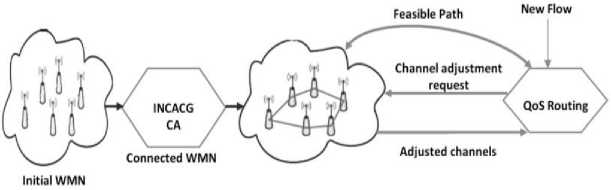
Fig.1. Solution framework
We present a new QoS routing protocol called Delay-Sensitive QoS Routing with integrated Admission Control to find a feasible path to satisfy the end-to-end delay requirement of the delay-sensitive flow. We assume users have a set of video and audio applications that require a specific end-to-end delay. The user data is transmitted between the user’s connecting backbone router (Mesh Access Point) to the gateway. The routing algorithm may choose the path with the shortest end-to-end delay and the longest hop-count to reduce the likelihood of QoS violations. It may hurt long-term system performance as measured by the admission ratio. So, algorithm has to consider this concern while selecting a path.
For end-to-end delay estimation, the delay experienced at each hop should be carefully determined. We use crosslayer routing metric ITLDA proposed in [22] to estimate a delay of each link on path between source and destination. Based on the packet delay model presented in [23], ITLDA estimates the one-hop delay of packet as sum of the average contention delay, transmission delay and queuing delay. As the queuing delay carries a noticeable part of the end-to-end delay [24], queuing delay has to be considered for estimating one-hop delay.
We implement DSQRAC by extending the AODV protocol. We run the protocol on top of network topology which is highly connected with minimum co-channel interference. The existence of common channel between two neighboring nodes (backbone mesh routers) defines a link between them. Each node keeps a table called Neighbor State (NS) table to store the state information of its connected neighbors. Table 1 shows structure of the table.
Table 1. Neighbor state table
|
Node |
Interface Used (IU) |
Channel Used(CU) |
Link Delay (msec) |
|
N 0 |
IU 0 |
CU 0 |
LD 0 |
|
. |
. |
. |
. |
|
. |
. |
. |
. |
|
N n-1 |
IU n-1 |
CU n-1 |
LD n-1 |
Each entry maintains information like neighbor node ID, node’s radio interface used, the common channel used to connect, delay of a link that exists between itself and its neighbor. Periodically each node broadcasts HELLO packets on all its radio interfaces to learn about the neighboring nodes and their corresponding neighbor state information. The ITLDA routing metric is used to update link delay that exists between itself and its neighbor. The link delay information is bi-directionally updated via the periodic exchange of HELLO message.
In the proposed DSQRAC protocol, to admit a new flow, we use admission controlled route discovery process. For this purpose, AODV’s RREQ control packets are used. In the route discovery process, the source node broadcasts a modified RREQ packet on all its radio interfaces. In the route discovery process, RREQ_RETRIES attempts will be carried out by the source for find feasible path. Before forwarding the RREQ packet, each node checks whether it has sufficient resources to serve the new flow without causing QoS violations of existing flows. Since DSQRAC uses only RREQ to discover a feasible path, it has simple operation and has low complexity.
To support the QoS routing, we modify the RREQ as follows. The modified RREQ packet is shown in the Fig.2. We add two new flags. i) LA (Last Attempt) flag → In our protocol, we want channel adjustment/reassignment to be initiated only for the ( RREQ_RETRIES ) th attempt, for this attempt, we set LA=1 and for other attempts we set LA=0 . ii) NC (Non-Confirmation of QoS) → For the RREQ with non-satisfying QoS, we set NC=1 . We add 5 new fields. i)
Required_E2EDelay (RE2ED) →This field stores the end-to-end delay that a user can tolerate for his/her application (User’s QoS bounds). ii) Total_E2EDelay (TE2ED) →This field stores cumulative end-to-end delay of partial path the from source to the current node. iii) Path_Accumulation_Vector →This field records all the nodes so far traversed by the RREQ packet. iv) Partial_Delay →This field stores end-to-end delay from source to node (bottleneck node) that fails to achieve the required QoS. v) Bot_Node_Id→This field stores the bottleneck node ID.
|
0|1|2|3|4|5|б|7 |
0 |
1 |
2 |
3 |
4 |
5 |
6 |
7 |
0|l|2|3|4|5|6|7 |
0|l|2|3|4|5|6|7 |
|
Type |
R |
G |
D |
u |
LA |
xc |
Hop Count |
|||
|
RREQJD |
||||||||||
|
Destination IP_Address |
||||||||||
|
Destination Sequence Number |
||||||||||
|
Originatoi_ IP_Address |
||||||||||
|
Originator_ Sequence_Number |
||||||||||
|
Total E2EDelay [Required E2EDelay Partial Delay |
Bot Node ID |
|||||||||
|
Path Accumulation Vector |
||||||||||
Fig.2. Modified RREQ control packet
When user flow arrives at Mesh Access Point (MAP), the receiving MAP acts source and tries to discover route to destination. Before sending RREQ packet, apart from filling all the pre-existing fields of the RREQ packet, the source node adds it ID into Path_Accumulation_Vector . In view of QoS routing, expect for the (RREQ_RETRIES)th attempt, for all (RREQ_RETRIES)-1 attempts, the source node sets flags D=1 and LA=0 and for last attempt we set flags D=1 and LA=1 . For all attempts, the Required_E2EDelay is initialized with maximum end-to-end delay that user can tolerate and Total_E2EDelay =0. The source node then broadcasts RREQ packet on its radio interfaces.
When intermediate node receives RREQ packet, it checks whether the same RREQ is received previously. If received previously, the node discards the received RREQ. If not received previously, then it checks the value of flags D, LA and NC . Intermediate node has to handle the following cases.
-
i) If D=1, LA=0 and NC=0 , for each of its connected neighbor NN i , it fetches the link delay l i between itself and the node NN i . The link delay l i is added to the Total_E2EDelay field of the RREQ packet. If new value of Total_E2EDelay is less than the value of Required_E2EDelay , the Total_E2EDelay is updated with new value and intermediate node appends its ID to the Path_Accumulation_Vector . The intermediate node updates its routing table and forwards the updated RREQ (feasible) packet to NN i . If new value of Total_E2EDelay is more than the value of Required_E2EDelay field, intermediate node does not forward RREQ to neighbor NN i . This means that the end-to-end path through that neighbor NN i cannot guarantees the required end-to-end delay. Once checked for all its connected neighbors, intermediate node discards current RREQ packet.
-
ii) If D=1, LA=1 and NC=0 (for the last attempt), as done previously, for each connected neighbor NN i , intermediate node fetches the link delay l i and adds l i to Total_E2EDelay . If the new value of Total_E2EDelay is less than the value of Required_E2EDelay , the Total_E2EDelay is updated and intermediate node appends its ID to the Path_Accumulation_Vector and forwards the updated RREQ (feasible) packet to the neighbor NN i . On other hand, if intermediate node fails to identify any of its connected neighbors to satisfy the required end-to-end QoS, the current intermediate node is labeled as one of ‘bottleneck node’ which has failed to achieve the required QoS. In this case, the intermediate node chooses the neighbor node Min_NN i which has shortest link delay among its connected neighbors. The intermediate node sets NC=1 to indicate that propagation through it is Non-Confirmation of QoS. Intermediate node then puts its ID in the Bot_Node_ID to indicate that, it is a one of possible node where channel reassignment can be done. Later it stores the value of Total_E2EDelay in the Partial_delay field. Finally, it appends its ID into Path_Accumulation_Vector , forwards the updated RREQ packet to the neighbor Min_NN i .
-
iii) If D=1, LA=1 and NC=1 (for the last attempt with Non-Confirming RREQ), among its connected neighbors, the intermediate node selects the neighbor Min_NN i that has the least link delay. It appends its ID into Path_Accumulation_Vector, updates its routing table and finally forwards the updated RREQ packet to the neighbor Min_NN i .
The algorithmic steps for RREQ packet processing at intermediate node are shown in Algorithm 1.
Whenever a RREQ packet reaches the destination node, destination checks that value of LA and NC flags. For the following three possible cases, the destination then generates the route reply (RREP) packet as per the modified format shown in the Fig.3. Similar to the modified RREQ packet format, the modified RREP has same NC flag, and other fields Partial_delay , Total_ E2EDelay , Required_E2EDelay , Bot_Node_ID, Path_Accumulation_Vector . The purpose of flags and new fields is same as that of modified RREQ packet.
Algorithm 1. RREQ packet processing at intermediate node
Process_RREQ_At_Intermdiate_ Node (New_RREQ)
-
1: if ( D==1 and LA==0 and NC==0 ) then // case i
-
2: for each connected neighbor router NN i do
-
3: New_Delay = Total_E2EDelay + Link_Delay l i
-
4: if ( New_Delay < Required_E2EDelay ) then
-
5: appends NN i ID to Path_Accumulation_Vector and forward RREQ via NN i
-
6: Once done for all neighbor and not found NN i , then discard RREQ
-
7: elif ( D==1 and LA==1 and NC==0 ) then // case ii: last attempt
-
8: for each connected neighbor router NN i do
-
9: New_Delay=Total_E2EDelay + Link_Delay l i
-
10: if ( New_Delay < Required_E2EDelay ) then
-
11: appends NN i ID to Path_Accumulation_Vector and forward RREQ through NN i
-
12: else
-
13: find the neighbor node Min_NN i that has the least link delay
-
14: set NC=1 and copy the Total_E2EDelay value into Partial _Delay
-
15: puts NN i router ID into Bot_Node_ID
-
16: appends NN i router ID to Path_Accumulation_Vector and forward RREQ via Min_NN i
-
17: elif ( D==1 and LA==1 and NC==1 ) then // case iii: last attempt
-
18: find the neighbor router Min_NN i that has the least link delay
-
19: appends NN i router ID to Path_Accumulation_Vector and forward RREQ via Min_NN i
0|l|2|3|4|5|6|7
0 1
3|4|5|6|7|0|l|2
3|4|5|6|7
0|l|2|3|4|5|6|7
Type
RAN
c
Prefix Sz
Hop Count
Source IP Address
Destination_IP_Address
Destination Sequence Number
Originator IP Address
Lifetime
Total_E2EDelay Required_F2FDelay PartialDelay | BotNodelD
Path_ Accumulationvector
Fig.3. Modified RREP control packet
The destination node has to handle the following cases.
-
i) If D=1, LA=0 and NC=0 , it means that received RREQ is not part of last ( RREQ_RETRIES )th attempt to find feasible path, the destination node waits for 3*NODE_TRAVERSAL_TIME to receive more feasible RREQ packets. With policy of the intermediate nodes discarding RREQ packet if they do not satisfy required end-to-end delay, only RREQ packets that satisfy the requirement reach the destination node. Once 3*NODE_TRAVERSAL_TIME time is over, destination node selects the path P i that has the least end-to-end delay and also satisfies required end-to-end delay of user application. It sets flag NC=0 . Then the destination node makes a routing table entry to the source and generates required RREP packet and unicast it back to source over the selected path. When each intermediate node receives the RREP packet, it creates/updates its routing table entry for the destination and sends the updated RREP packet towards the source.
-
ii) If D=1,LA=1 and NC=0 , it means that received RREQ is part of last ( RREQ_RETRIES ) th attempt to find feasible path, the destination node processes the RREQ packet as processed in previous case and unicast the RREP packet back to source node.
-
iii) If D=1, LA=1 and NC=1 , it means that received RREQ is part of last (RREQ_RETRIES)th attempt to find feasible path and received RREQ with non-confirming QoS, the destination node then waits for 3* NODE_TRAVERSAL_TIME time to receive all non-confirming RREQ packets. Once waiting time is over, among the received RREQs, the destination selects a path that has the least end-to-end delay. From the corresponding RREQ packet, the destination node learns i) the bottleneck node that did not satisfies the required QoS, ii) the partial path from source to bottleneck node and the related partial delay. Destination node then copies the values of Partial_delay , Path_Accumulation_Vector, Total_E2EDelay, required_E2EDelay, Bot_Node_ID , from respective fields of RREQ packets into the corresponding fields of RREP packet and set NC=1 . Finally, destination node unicast RREP packet back to the bottleneck node.
The algorithmic steps for RREQ packet processing at destination node are shown in Algorithm 2.
Algorithm 2. RREQ packet processing at destination node
Process_RREQ_At_Destination_Node(New_RREQ)
-
1: if ( New_RREQ == First_Received_RREQ ) then
-
2: if ( D==1 and LA==0 and NC==0 ) then // case i
-
3: wait for 3*NODE_TRAVERSAL_TIME to receive RREQ packets
-
4: from all the received RREQ packets do
-
5: find the path P i that has the least end-to-end delay and satisfies end-to-end QoS
-
6: make the routing table entry for source node
-
7: generate the RREP packet, set NC=0 and unicast it back to source over the path P i
-
8: elif ( D==1 and LA==1 and NC==0 ) then // case ii: last attempt
-
9: Repeat steps from 3 to 7
-
10: elif ( D==1 and LA==1 and NC==1 ) then // case iii: last attempt
-
11: wait for 3*NODE_TRAVERSAL_TIME to receive RREQ packets
-
12: from all the received RREQ packets do
-
13: find the path P i that has the least end-to-delay
-
14: copy the Partial_delay, Path_Accumulation_Vector, Bot_Node_ID, Total_ E2EDelay, Required_E2EDelay from received RREQ packet to RREP packet and set NC=1
-
15: unicast RREP back to bottleneck router over the path P i
When RREP packet arrives at intermediate node, it checks the value of NC flag. If NC=0 , it forwards the RREP packet as done in normal AODV operation. If NC=1 and the intermediate node is not the bottleneck node, it finds next hop node on reverse path from the Path_Accumulation_Vector field of the received RREP and forwards the RREP packet to the next node. Once the RREP packet with NC=1 reaches the bottleneck node, that node will triggers the channel reassignment to adjust the channels and tries to find the feasible path. The algorithmic steps of RREP packet processing at the intermediate node are listed in Algorithm 3.
Algorithm 3 Algorithm for RREP packet processing at intermediate node
Process_RREP_At_ Intermdiate_Node( )
1: if (NC==0) then
2: forward the RREP packet as done in AODV
3: elif ((NC==1 and intermediate_node != bottleneck_ node) then
4: forward the RREP packet to next router on reverse path
5: elif ((NC==1 and intermediate_ node == bottleneck_ node) then
6: triggers the channel reassignment to adjust the channels
5. Performance Evaluation
As routing and channel assignment schemes are interdependent on each other, by adjusting the channels on different links, we can increase the available bandwidth of links and hence enhance the likelihood of discovering a feasible path. For the simplified channel adjustment at bottleneck node, adjustment process should use only local information and should have only the local impact. Along with these requirements, adjustment process should have a smaller number of channel switches/changes. Through the Path_Accumulation_Vector bottleneck of RREP packet, bottleneck node ‘ e ’ gets to know it’s neighbor node ‘ f ’ through which the path is existing between given source and destination. Once neighbor ‘ f ’ is identified, node ‘ e ’ will change the channel on the link l ef that exist between bottleneck node ‘ e ’ and its neighbor ‘ f ’. When node ‘ e ’ is about change its channel to any other channel, node ‘ e ’ first it checks the existence of chain puzzle problem. Fig.4. illustrates the chain puzzle problem in the given network topology, where each node has two radio interfaces. If node ‘ e ’ changes channel from C 1 to C 2 , then to maintain connectivity with node ‘ g ’, node ‘ f ’ has to change channel from C 1 to C 2 between itself and ‘ g ’. Similarly, node ‘ g ’ also has to change channel from C 1 to C 2 between itself and ‘ h ’ and node ‘ h ’ also has to change channel from C 1 to C 2 between itself and ‘ i ’. The change of channel from C 1 to C 2 on link l ef will result in chain of channel changes on the other neighboring links. Such chain of channel change is called as chain puzzle problem. If more numbers of nodes are involved in chain puzzle, then it may lead to large overhead. The large size chain interrupts lot of flow transmissions. So, because of its practical impacts, before a bottleneck node is allowed to change the channel, node has to check the existence of chain puzzle problem. When a node ' e ' selects a new candidate channel C i and discovers that a node not within its 2-hop distance also requires changing the channel to maintain their link connectivity, then this results in a chain puzzle and C i is not a feasible channel.
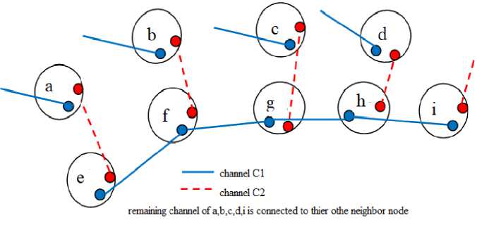
Fig.4. Chain puzzle problem
For QoS routing, along with checking of chain puzzle problem, the channel adjustment process has to check whether the channel change of bottleneck node results in the drastic change of link delay of nearby 2-hop links. Such change may violate QoS of existing flows. The channel used on 2-hop links determines bandwidth available on each of the link. So, the change of channel on one link should not reduce the other link’s available bandwidth and hence the increase link delay. Hence, before node makes such channel change it should check whether such change increases link delay of any of its 2-hop links. If it does, then intermediate node should abort the channel adjustment process. If not then, it should go for the change of channels on respective links. Before the bottleneck node changes the current channel to the new channel, it follows the mechanism similar to that of [25] and send channel request message Ch_Change_Reqest to all its neighbor nodes to confirm that currently none of them are involved in any channel change. It prevents simultaneous channel changes. If the neighbor node is not involved in the channel change, then it sends her Ch_Change_Accept message, otherwise it sends the Ch_Change_Reject message. If bottleneck node does not receive any Ch_Change_Reject message then, through the Update_Channel message requests all the corresponding nodes to change the channel. Once all the channels are changed, then the bottleneck node resumes route discovery process. For this, a new RREQ packet is created. In new RREQ, from the Path_Accumulation_Vector field of received RREP packet, partial path from source to bottleneck node is calculated and copied into Path_Accumulation_Vector field of new RREQ packet. Set LA=1, D=1 and NC=0. Then copy the value of Partial_Delay of RREP into Total_E2EDelay field of new RREQ, this value helps in calculating the final end-to-end delay. Finally copy the required other fields form RREP into respective fields of new RREQ and start processing the New RREQ in normal way.
Through the simulations results, we compare the performance of proposed DSQRAC protocol with existing schemes. The ns-3 simulations are used to verify the effectiveness of DSQRAC. The details of the simulation are tabulated in Table 2.
As the performance of the proposed QoS routing protocol is to increase the flow acceptance rate of delay-sensitive flows without affecting the already admitted flows, we evaluate the performance using the acceptance rate and average throughput and end-to-end delay with lower routing overhead. First, we measure the flow acceptance rate. The DSQRAC tries to find a feasible path from source node to destination for maximum of RREQ_RETRIES attempts. For the (RREQ_RETRIES)th attempt the channel adjustment is initiated to adjust the channel to increase the chance of finding the feasible path. To show how channel adjustment aids in finding the feasible path, we compare the performance of DSQRAC with channel adjustment (DSQRAC_DCA) with modified version of the DSQRAC i.e DSQRAC_SCA without the channel adjustment (Static Channel Assignment) and with EstQoS [14]. For this comparison, we conduct simulation as per the details tabulated in Table 2, with number of radio interfaces R=2 and number of orthogonal channels C=4. The average of 5 simulations is used for comparison. Neither DSQRAC_SCA nor EstQoS make an effort to adjust the channels to increase the acceptance rate. DSQRAC_DCA tries to adjust the channels to increase the acceptance rate. The Fig. 5 shows the performance of all the protocols. The flow acceptance rate of DSQRAC_DCA is 14% and 19% better than EstQoS and DSQRAC_SCA respectively.
Fig. 6 shows the effect of the number of available channels. We compare the performance with R=2 and C=3,4,5,6, with arrival rate of 4 demands per minutes. As seen from the Fig. 6, it is clear that with a greater number of channels available for channel allocation, there is increase in the acceptance rate of all the protocols, especially with DSQRAC and EstQoS.
Table 2. Simulation details
|
Parameter |
Value |
|
Simulation Time |
240 seconds(4 mins.) |
|
Network Area |
1000*1000 sq.mt |
|
Topology |
Grid topology of size 7*7 |
|
Number of nodes |
49, with 1 node acting as gateway |
|
Max. Data Rate |
11Mbps |
|
Queue Type and Size |
Drop Tail and 50 |
|
Traffic and Packet size |
Video streaming and 1024 bytes |
|
Transmission/ Interference Range |
250M/550M |
|
Max. number of channels(m) / radio interfaces (R) |
12/4 |
|
CWmin and CWmax |
32 and 1024 |
|
Target Delay |
100ms |
|
AODV RREQ_RETRIES |
2 |
|
AODV NODE_TRAVERSAL_TIME |
8ms |
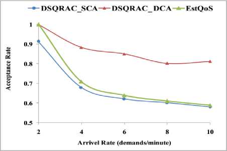
Fig.5. Acceptance rate
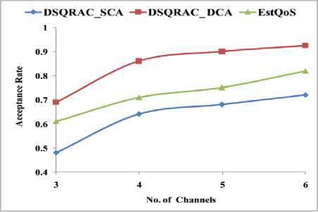
Fig.6. Acceptance rate with C=3,4,5,6
Further we will evaluate the performance of DSQRAC with EstQoS [18] and AODV-MR [26] multi-radio AODV which uses hop-count as routing metric. We use average throughput, average end-to-end delay and routing overhead to compare the performance of three protocols. We simulate WMN with 20 different UDP real-time data flows arriving randomly from different source nodes. The flow transmission rate is 30 packets/sec.
In DSQARC, as RREQ packets are forwarded only through the intermediate nodes that have enough resources to support the admission of new flow, a smaller number of RREQ packets are gets transmitted in the network. With a smaller number of RREQ packets, more bandwidth will be available bandwidth for data transmissions. More available link bandwidth results in more throughput and less packet delay.
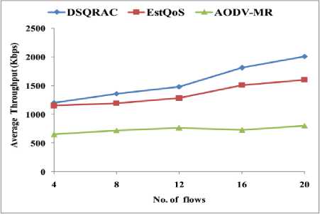
Fig.7. Average throughput
The Fig.7 shows average throughput of all three protocols. Initially with a smaller number of flows, the performance of protocols is almost the same. With increasing number of data flows, the interference among the flows increases. Since AODV-MR uses minimum hop-count to discover the paths, its average throughput is the worst among the three protocols. In EstQoS, only transmission delay and channel access delay are used to compute the link delay without considering loads of the forwarding nodes. Because of this, EstQoS may discover path through the congested nodes. With increasing number of data flows, the contention among the nodes increases and results in degrading of throughput. As the link delay computation of DSQRAC is based the transmission delay and channel access delay and loads of the forwarding intermediate node, it discovers the lightly loaded paths. Due the proper load distribution, the average throughput of DSQRAC is better than other two protocols. The average throughout of DSQRAC is 14.4 % and 53% better than EstQoS and AODV-MR respectively.
Figure 8 shows average end-to-end delay of all three protocols. The end-to-end delay of packet depends on the channel access, transmission and queuing delays. If path is selected only on the basis channel access delay and transmission delay (i.e. MAC service time), more packets will get transmitted through the already loaded forwarding node and hence increase the packet queuing delay. As DSQRAC link delay computation includes all three possible delays, it selects a path through the lightly loaded nodes. So, the average end-to-end delay of DSQRAC is less among the other protocols. The average end-to-end delay of DSQRAC is 21.18% and 51.9% less than EstQoS and AODV-MR respectively.
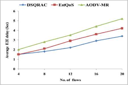
Fig.8. Average E2E delay
Figure 9 shows the routing overhead of three protocols. As DSQRAC implemented with AODV and EstQoS implemented with OLSR, almost same number of HELLO packets are used for maintaining node/link status. As RREQ gets forwarded only on QoS fulfillment, a smaller number of RREQ packets are used for path discovery. In OLSR implementation of EstQoS, a greater number of TC and MID routing control packets are transmitted for route maintenance, the routing overhead of EstQoS is more. In AODV-MR RREQ control packets are transmitted on all the radio interfaces of node. It has more routing overhead as compare to the DSQRAC. DSQRAC produces 29.4% and 43.8% less routing overhead as compared to the EstQoS and AODV-MR respectively.
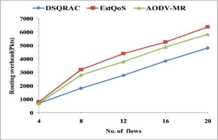
Fig.9. Routing overhead
6. Conclusions
WMNs need to support the effective implementation of various multimedia applications. The multimedia applications require assured QoS to fulfill the user requirements. The QoS routing in WMNs needs to guarantee the QoS requirements of multimedia applications. The admission control is the primary traffic control mechanism deployed to provide QoS provisioning. A new QoS routing protocol with admission control called delay-sensitive QoS routing with integrated admission control i.e. DSQRAC, is designed to control the admission of delay-sensitive flows. The primary focus is on the end-to-end delay requirements of delay-sensitive multimedia applications. A delay-aware crosslayer routing metric is used to find the feasible path. The QoS routing protocol is implemented using the AODV routing protocol. Since the RREQ packets consume a noticeable amount of network resources, the RREQ packets are forwarded only by the few nodes that guarantee the required delay requirement. Such a delay-sensitive controlled flooding mechanism avoids the unnecessary flooding of RREQ packets and makes provision to save the possible network resources to be consumed by such RREQs. As channel assignment and routing together define the availability of network resources, when required, the channels are adjusted to aid the QoS routing to increase the likelihood of accepting a new flow. The simulation results confirm that the performance of the DSQRAC routing protocol outperforms the existing protocols. The flow acceptance rate of DSQRAC_DCA is 14% and 19% better than EstQoS and DSQRAC_SCA respectively.
References Delay-sensitive Quality of Service Routing with Integrated Admission Control for Wireless Mesh Network
- I. F. Akyildiz, X. Wang, and W. Wang, “Wireless mesh networks: a survey,” Computer Networks, vol. 47, no. 4, pp. 445–487, Mar. 2005, doi: 10.1016/j.comnet.2004.12.001.
- Md. I. Hussain, N. Ahmed, Md. Z. I. Ahmed, and N. Sarma, “QoS Provisioning in Wireless Mesh Networks: A Survey,” Wireless Pers Commun, Aug. 2021, doi: 10.1007/s11277-021-08893-3.
- L. Khoukhi, H. Badis, L. Merghem-Boulahia, and M. Esseghir, “Admission control in wireless ad hoc networks: a survey,” J Wireless Com Network, Vol. 2013, No. 1, p. 109, Dec. 2013, doi: 10.1186/1687-1499-2013-109.
- L. Chen and W. Heinzelman, “A Survey of Routing Protocols that Support QoS in Mobile Ad Hoc Networks,” IEEE Network, Vol. 21, No. 6, pp. 30–38, 2007, doi: 10.1109/MNET.2007.4395108.
- C. Perkins, E. Belding-Royer, and S. Das, “Ad hoc On-Demand Distance Vector (AODV) Routing,” RFC Editor, RFC3561, Jul. 2003. doi: 10.17487/rfc3561.
- O. M. Zakaria et al., “Joint Channel Assignment and Routing in Multiradio Multichannel Wireless Mesh Networks: Design Considerations and Approaches,” Journal of Computer Networks and Communications, Vol. 2016, pp. 1–24, 2016, doi: 10.1155/2016/2769685.
- V. Kone, S. Das, B. Y. Zhao, and H. Zheng, “QUORUM—Quality of Service in Wireless Mesh Networks,” Mobile Netw Appl, Vol. 12, No. 5–6, pp. 358–369, Dec. 2007, doi: 10.1007/s11036-008-0050-8.
- X. Cheng, P. Mohapatra, S.-J. Lee, and S. Banerjee, “MARIA: Interference-Aware Admission Control and QoS Routing in Wireless Mesh Networks,” in 2008 IEEE International Conference on Communications, Beijing, China, 2008, pp. 2865–2870. doi: 10.1109/ICC.2008.540.
- D. Manikantan Shila and T. Anjali, “An Interference-Aware Admission Control Design for Wireless Mesh Networks,” J Wireless Com Network, Vol. 2010, No. 1, p. 106520, Dec. 2010, doi: 10.1155/2010/106520.
- B. Bakhshi, S. Khorsandi, and A. Capone, “On-line joint QoS routing and channel assignment in multi-channel multi-radio wireless mesh networks,” Computer Communications, Vol. 34, No. 11, pp. 1342–1360, Jul. 2011, doi: 10.1016/j.comcom.2011.02.001.
- P. Zhao, X. Yang, J. Wang, B. Liu, and J. Wang, “Admission control on multipath routing in 802.11-based wireless mesh networks,” Ad Hoc Networks, Vol. 11, No. 8, pp. 2235–2251, Nov. 2013, doi: 10.1016/j.adhoc.2013.05.006.
- I. Hussain, N. Ahmed, D. K. Saikia, and N. Sarma, “A QoS-aware multipath routing protocol for WiFi-based long distance mesh networks,” in 2014 2nd International Conference on Emerging Technology Trends in Electronics, Communication and Networking, Surat, India, Dec. 2014, pp. 1–8. doi: 10.1109/ET2ECN.2014.7044990.
- S. K. Dhurandher, I. Woungang, M. S. Obaidat, K. Kumar, M. Joshi, and M. Verma, “A Distributed Adaptive Admission Control Scheme for Multimedia Wireless Mesh Networks,” IEEE Systems Journal, Vol. 9, No. 2, pp. 595–604, Jun. 2015, doi: 10.1109/JSYST.2013.2296336.
- D Chakraborty, “EstQoS: establishing quality of service in multirate multihop wireless mesh networks through available bandwidth computation and efficient admission control”, Int. J. Ad Hoc and Ubiquitous Computing, Vol. 22, No. 4, pp.265–273, Jul. 2016, doi:10.1504/IJAHUC.2016.078116.
- P. Reddy and P. V. Krishna, “Energy aware Cross- layer-based connection admission control mechanism for wireless mesh networks,” IJSGGC, Vol. 1, No. 1, p. 73, 2016, doi: 10.1504/IJSGGC.2016.077301.
- J. Dromard, L. Khoukhi, R. Khatoun, and Y. Begriche, “Towards combining admission control and link scheduling in wireless mesh networks,” Telecommun Syst, Vol. 66, No. 1, pp. 39–54, Sep. 2017, doi: 10.1007/s11235-016-0273-0.
- S. Bhojannawar and S. Mangalwede, “Interference, Traffic Load and Delay Aware Routing Metric for Wireless Mesh Network,” Adv. Electr. Comp. Eng., Vol. 21, No. 1, pp. 57–64, 2021, doi: 10.4316/AECE.2021.01006.
- P. Raptis, V. Vitsas, K. Paparrizos, P. Chatzimisios, and A. C. Boucouvalas, “Packet delay distribution of the IEEE 802.11 distributed coordination function,” in Proc. 6th IEEE International Symposium on a World of Wireless Mobile and Multimedia Networks, Taormina-Giardini Naxos, Italy, 2005, pp. 299–304, doi:10.1109/WOWMOM.2005.74.
- H. Li, Y. Cheng, C. Zhou, and W. Zhuang, “Routing metrics for minimizing end-to-end delay in multiradio multichannel wireless networks,” IEEE Trans. Parallel Distrib. Syst., Vol. 24, No. 11, pp. 2293–2303, Nov. 2013, doi:10.1109/TPDS.2012.327.
- B.-J. Ko, V. Misra, J. Padhye, and D. Rubenstein, “Distributed Channel Assignment in Multi-Radio 802.11 Mesh Networks,” Jan. 2007, WCNC 2007. [Online]. Available: https://www.microsoft.com/en-us/research/publication/distributed-channel-assignment-multi-radio-802-11-mesh-networks/
- A. A. Pirzada, M. Portmann, and J. Indulska, “Performance analysis of multi-radio AODV in hybrid wireless mesh networks,” Computer Communications, Vol. 31, No. 5, pp. 885–895, Mar. 2008, doi: 10.1016/j.comcom.2007.12.012.
