Design and development of a smart device for energy monitoring and control of domestic appliances: an android application

Author: Anupama S., U. B. Mahadevaswamy
Journal: International Journal of Image, Graphics and Signal Processing @ijigsp
Article in issue: 1 vol.10, 2018.
Free access
Energy management system for the household appliances in terms of monitoring and control is described in this paper. Monitoring the energy consumption is the initial step to reduce it. The smart device is designed and developed that will monitor the load device parameters like voltage, current, power factor, power consumption and frequency. The load device is made to turn OFF/ ON based on the status of the device through the mobile application. To get the measured data and to control the load device an Android application has developed, which uses a mobile-enabled Bluetooth to communicate with the Bluetooth low energy module, which is interfaced to the host microcontroller. Bluetooth module is used as it works well for home automation applications. The proposed device has a simple design, low power consumption, cost-effective and easy to interact with the user.
Energy management system, Smart plug, Bluetooth low energy(BLE), Relay, Android application
Short address: https://sciup.org/15015931
IDR: 15015931 | DOI: 10.5815/ijigsp.2018.01.05
Text of the scientific article Design and development of a smart device for energy monitoring and control of domestic appliances: an android application
Energy management system refers to the hardware and software system that can monitor the energy usage and also sends the feedback to the owner. This also has the capacity to control the usage of energy using advanced control system for the home devices. Energy management is the key solution to save energy. It is the means to control and reduce the energy consumption in an organization. This leads to a reduction in cost, reduction in carbon emission and reduce risk. There are many ways to manage the energy consumption i.e., by metering the energy consumption and collecting the data, finding the opportunity to save energy and targeting the opportunities to save energy.
Monitoring the energy consumption is the best way of reducing it. Once the energy usage of home appliances are known individually it constantly shows the way of reducing it. Almost every house has an electricity meter which measures the energy consumption of whole house, but not the readings of individual appliances. So there is a need to design a system that monitors and controls the device based on the requirement.
The Electricity meter is the device which measures the electrical energy consumed by the appliances. These appliances draw the electrical energy from the main power supply. It is known that the energy meters are installed outside the building and the billing data is available only at the end of the month. But with this data, it is not possible to see the clear picture of energy consumption. The energy conservation-minded people are always interested to know about the utilization of energy by them so they go for other alternatives like smart devices for energy measurement namely power plug meter or smart plug meters.
Power plug meters are the meters which measure the energy consumption of appliances which are plugged into it. These meters are connected between the wall socket and the appliance that display parameters like voltage, current, energy etc. These types of meters do not contain any communication media to send the measured data to other devices. So to overcome this problem the smart plug meters are introduced.
Smart devices are usually connected to other devices via a wireless protocol like Wi-Fi, Bluetooth, 3G etc. Some of the well-known smart devices are the smart phone, smart watch and smart band. A smart plug meter is one among the smart device which is used for continuous monitoring and automatic control of the plugged appliance. Smart plug devices are lightweight, simple in design and portable. This consists of few buttons to perform some reset operation and others. In this paper, an attempt is made to implement the Bluetooth low energy technology to the smart plug device. As compared to other wireless technology BLE is more suitable for the home application.
Bluetooth with a low energy functionality is suitable for the devices that run for the longer duration under power sources such as coin cell batteries. BLE is basically built for IOT applications. The other name for Bluetooth low energy is Bluetooth smart. As compared with classic Bluetooth, BLE provides reduced power consumption and cost with the same communication range.
Android application development is a process by which the application is developed on an Android operating system for android phones. An Android version from 4.3 supports BLE, so it is possible to discover, connect and exchange the data operations. There are many android software development tools available; namely android studio, eclipse etc. generally the programming language used to develop an Android application is java. In this work, the tool used to develop an android application is MIT app inventor. The application can be easily developed using this tool because the code is designed using blocks which is easy to understand.
-
II. Literature Survey
The electricity meter measures the electricity consumption and displays it on the screen, but this will not display the energy consumption of an individual device. Because of this, it is not possible to analyze the energy usage and wastage of energy. With increased awareness in energy conservation, companies and research groups have attempted to design power monitoring solution residential and commercial use. In addition to the related commercial product, the power monitoring, and control system has been proposed and implemented.
In [1], the author proposed a smart monitoring and controlling system for household electrical appliances in real time. This paper mainly focuses on remote controlling of devices without the aid of human efforts. For remote monitoring and controlling the technology used is GPRS. This system operates the device and monitors its power consumption from the remote location using an Android UI and it also focuses on humanfriendly technical solution household appliances in terms of monitoring and control.
In [2], the author highlighted the need of energy monitoring as the part of the home energy management system. The system consists of two divisions, one is measurement unit and another one is wireless communication unit (BLE). The BLE module is connected to the energy measurement unit via UART communication. This Utilizes one-way broadcasting mode of BLE to transfer the data from the measurement device to the BLE-enabled mobile device. The application in mobile aggregate the energy consumption data.
In [3], the author proposed the Wi-Fi technology for home energy monitoring and control of appliances is done remotely using an application in the Android phone. The design comprises of three modules mainly the server, equipment interface module, and product bundle. The major hardware required are Arduino board, Wi-Fi shield, relay and breadboard. This paper uses android based application platform, but in future, they are trying to implement it on iOS and Blackberry operating system. The major drawback of this technology is, in most of the healthcare related products and the Wi-Fi technology is not used because of prolonging exposure may affect the human health.
In [4], the BLE technology used for monitoring and controlling of household products using the smart plug as a reference device. An application is implemented on Android OS. The plug provides API for power consumption measurement and control operation. The main goal of the home automation system is to optimize power consumption. For this, an application is developed in the mobile phone. The drawback of this system is, this will not meet the objectives in an automated way.
In [5], the author proposed home energy management system for reduction of energy consumption. In this paper, they designed and developed a smart plug with Zigbee sensor for measuring power consumption. The smart plug using Zigbee is capable of processing and analyses the sensor for voltage and current measurement and relay can be controlled based on this data.
In [6], the author discussed on efficient utilization of electric energy in an energy management system. Energy management system contains demand side management, which is a solution for existing structure of a smart plug. In this paper, they have made an attempt to design a smart plug to provide power reduction without disconnecting the plugged device OFF. Due to the reduction of voltage, there is an increase in harmonic distortion in the device, so the lifetime of appliances might be affected. To send the collected parameter to other devices like PC or mobile devices the smart plug uses Zigbee protocol for communication.
In [7], the author studied about the energy consumption and generation to minimize the energy cost. As the usage of home energy increases, there is a deployment in the renewable energy system. So there is a need for the home energy management system. The Zigbee is used to monitor the energy consumption of appliances and PLC is used to monitor the energy generation of renewable energies. The home server is created to gather the information of both energy consumption and generated data, analyze them and send the same data for remote control management server.
In [8], author primarily focuses on monitoring and control of household appliances in real time. They monitor the electrical parameters like voltage, current and power consumed. The wireless sensor network is used for energy control services. This consists of sensors which receive the data from various XBee module i.e. from the home devices. The data which is sensed is sent to the Zigbee coordinator. The Zigbee send the same data to the connected host computer via USB, this data is stored and can also remote controlled.
In [9], a power management system for home appliances using a wireless sensor network has been designed and tested. The sensed and stored information of home appliances are sent by the home gateway to the data server which is cloud-based.
In [10], authors describes the design, implementation, and testing of a wireless sensor and actuator network for monitoring the energy use of electric appliances in a home environment.
In [11], authors explains the importance of home automation. Automation is the use of control systems and information technologies to reduce the need for human work in the production of goods and services. Owner can control loads (on/off) automatically by mobile using GSM technology from anywhere.
In [12], authors discussed about the design and development of a smart home system that allows control of home appliances using both Bluetooth and GSM technology. The system is controlled using a dedicated android based application which ensures convenience and ease of use.
In [13], authors describe how to design a low-cost touch screen using the equipment that are found in the local market and how it can be used in our daily life such as to control the house hold electrical devices. Using touch screen, the home automation system becomes very easy to operate.
-
III. Motivation
As the demand for electrical energy increase for home appliances the cost of electrical energy also increases exponentially. So there is a need for monitoring the energy usage of the appliances and to turn off the device in non-operating condition. This is the best idea to save the energy for future use. The system should be like it gives energy consumption in kWh in real time. This emphasizes to lower the energy usage and helps to enhance the proper utilization of resources.
This made a way to design a device that continuously monitors and controls the electrical appliances and displays some parameters like voltage, current and subsequently calculates the power consumption. The developed system is proved to be low cost, more efficient and user-friendly which helps to save electricity usage of customers.
-
IV. Problem Statement
As the usage of electricity increases the cost per unit also increases which is a negative feedback to the environment because, as the demand increases the production of energy also increases. Keeping all this in mind a product which continuously monitors the energy usage and can be controls whenever it is necessary came to existence. One such product is smart meters. This type of meter monitors the energy consumption of house and sends data to the user. So it is easy to analyze the energy usage and can be controlled according to the data.
Even though smart meters are installed in utility side this measure the energy consumption of whole house but not the individual appliances energy usage. To overcome from this problem smart devices like power plug and smart plug meters came into the market. These type of meters helps to monitor and control the individual appliance efficiently. Motivated by this a product has been designed and developed which is a low energy management system and work efficiently in real time.
-
V. Objectives
Initially the work started with building a basic block diagram of the system based on the knowledge obtained from the literature survey carried out. In the next step the selection of the hardware components based on its cost, performance, requirement of space and accuracy is done, then designing a hardware module with the components selected and testing of a module to check its performance. The major objectives of the proposed work are listed below.
-
• To Design and develop a hardware module for measurement of voltage, current, power, power factor, and frequency
-
• To interface the hardware module with microcontroller and develop an embedded C code for calculation of different parameters
-
• Development of Android application for monitoring, control of devices and Testing of Bluetooth module by establishing the communication between app and Bluetooth module.
-
• To make an analysis of power consumption of various devices and turn off the load device based on monitored data.
-
VI. Implementation
-
A. Proposed block diagram
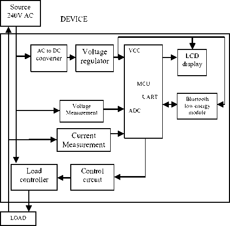
Fig.1. Proposed Block Diagram For Monitoring And Controlling Purpose.
The block diagram gives the complete picture of the system. This consists of major blocks like power supply unit, microcontroller, LCD display, voltage and current measurement unit, Bluetooth module, Relay Controller. Each block has its own functionality to perform and works together to give the desired output. The block diagram is shown in Fig.1
-
1) Power supply unit
The Power supply unit is one of the most important part in a system. Its primary function is to convert one form of electrical energy to another. The power supply unit is designed based on the load which we connect. The AC supply from the socket is converted to DC voltage by using different types of diode, capacitor, inductor and filter circuits. To get a constant dc voltage a dc to dc buck converter is used which gives an output of 12V which is used to drive the relay circuit. This output is fed to the voltage regulator 7805 to get a voltage value of 5V. the 5V is step down to 3.3V which is used by microcontroller unit and BLE module. The block of power supply system is shown in Fig. 2.
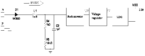
Fig.2. Block Diagram of Power Supply Unit Which Provides Different Voltages
-
2) Microcontroller unit
The Microcontroller unit is one of the most important part in a system. All the components in a block are connected to the microcontroller unit for monitoring and control of the power consumption and relay respectively. The inbuilt ADC in microcontroller helps in conversion of measured voltage and current values to its digital equivalent value. The microcontroller used in this work is RL78 a new generation microcontroller family in Renesas electronic family, Fig.3 represents Renesas RL78 based microcontroller. It has a 16 bit CISC architecture with 3 stage pipeline. RL78 is basically designed for low power application which enables in providing energy efficient system with low cost. The operating voltage is 1.9V to 5.5V. has on-chip ROM of 6K to 8K and flash memory of 64K or 128K and consists of serial interfaces like UART, I2C, and IrDA. A/D converter and 24 bit ΔƩ A/D converter.
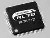
Fig.3. Renesas based Microcontroller
-
3) Voltage and Current measurement unit
For the calculation of power, the important parameters required are voltage, current and power factor. The sensed voltage and current are given as input to the ADC which is in the form of voltage. This input voltage value should be less than the reference voltage value of ADC. The block diagram shows the voltage measurement unit as shown in Fig.4
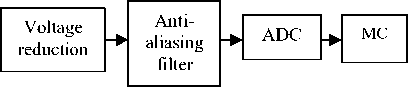
Fig.4. Voltage measurement block diagram.
When the AC input is sensed the voltage is reduced using a resistive ladder circuit, the output of this circuit may contain the noise factor. So to eliminate this noise an anti-aliasing filter is used. The step downed voltage is given to the ΔƩ ADC for further calculation. The sampling frequency of ADC is 2KHz so the number of samples in each cycle is 40. After conversion sampled values are stored in some register.
For current measurement, the main component used is a shunt resistor. The voltage across this resistor is measured and again step down to its lower voltage value. The next steps are same as that of voltage measurement process. Fig.5 shows the measurement of current across the shunt resistor.
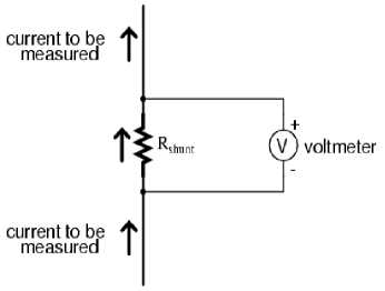
Fig.5. Current measurement circuit
Once the voltage and current are calculated the next step is to calculate the power factor. Power factor is the ratio of true power to the apparent power and also defined as the cosine of the phase angle of voltage and current. For P.F calculation first, find out the active power. The voltage and current samples obtained after sampling are multiplied instantaneously to get the instantaneous power, then the summation of power is done and divided by the number of samples as shown in (1).
^Instantaneous Power) Active Power =---------------------No. of samples
= (1)
Where, N = number of samples.
The Apparent Power is given by ,
Apparent Power = Vrms * Irms (2)
Where,
V rms = rms value of voltage
I rms = rms value of current
The rms value of voltage is calculated as
V rms = J N Z N=1 V ? (3)
The rms value of current is calculated as
Irms J N Z Nr 1 2 (4)
Then the P.F is calculated as
P.F
Active Power
Apparent Power
-
4) Bluetooth module
BM78 is a dual mode Bluetooth module i.e. classic type and Bluetooth Low Energy. It has a Bluetooth core specification of 4.2, which helps to improve the throughput and security and solution for IoT and embedded application. BM78 helps to bridges the customer product to tablets or Smartphone for data transfer. Coming to portable devices the design is made in such a way that the current consumption is Minimum to expand the life of the battery. Some of the features are It has Bluetooth 4.2 standard, this supports UART, I2C interface has an ISM band of 2.402GHz to 2.480GHz, it has an integrated public profile like GAP, GATT, ATT, SMP and L2CAP, the operating voltage range is about 3.3V to 4.2V and operating temperature of -20oC to +70oC. Fig.6 represents the BM70 Bluetooth module.
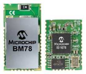
Fig.6. BM78 Bluetooth Module
-
B. PCB design
For designing the hardware module the software tool used is Cadstar. Cadstar is one among the EDA design tool which helps to draw the schematic and transfer them to the PCB layout. While designing the schematic the components are provided by the inbuilt library which contains all the parts required for PCB design. Once the schematic is done next check for errors in connections then this is transferred to the PCB layout. In PCB layout the components are not placed properly. So there is an option to place the components in the desired place according to the requirement. After placing components the routing can be done manually and/or through automatic routing. Once the PCB layout is done the next stage is the manufacturing of PCB based on the data given by Gerber file and Bill of materials. Fig.7 shows the final PCB design done using Cadstar.
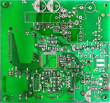
Fig.7. The outlook of the designed PCB
-
C. Working principle
The main aim of the work is to build an energy management system for home devices in terms of monitoring and controlling. This continuously monitors the load and displays the data in the display window. The data can be like voltage, current, power, power factor and the frequency value of a device. The controlling part includes the on/off of the load device based on its state. This work consists of 2 divisions of work, namely hardware design and android application development. The hardware design contains designing of PCB with necessary components and interfaces the BLE module. The software part consists of the development of Bluetooth enabled Android application in Smartphone.
As seen in block diagram the power supply unit of the product is connected to the main source 230V AC supply. The 230V is stepped down into 12V DC voltage using a buck converter and this voltage is used by relay driver circuit. The same voltage is step down to 5V DC using 7805 voltage regulator and is used by microcontroller and LCD display and Bluetooth module requires 3.3V as supply voltage which is provided by LDO.
For the measurement of current and voltage value, the shunt resistor is used, that measures the data which is in Analog form. But the input to the ADC should be in terms of voltage, so the measured current is defined in terms of voltage using current measurement circuit. Once the voltage and current value are digitized the controller calculates the power consumption of the load and displays the same data in an LCD display.
The Bluetooth module is interfaced to the host MCU to send the measured data to Smartphone whenever the request arises. Here the Bluetooth module is a communication media between measurement unit and android application. This also consists of EEPROM as an external storage device. The connection of BLE module to MCU is shown in Fig 8.
Display X unit
Bluetooth module
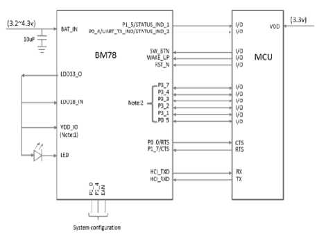
Fig.8. Interface diagram Of Microcontroller Unit with Bluetooth Module(BM78)
Coming to the controlling part the device used is an Electromechanical latched type relay. The relay is connected to the load device and the current measurement circuit. When the sensing device senses the variation supply side or in the load side this will send the signal to the microcontroller intern the trigger signal is sent to the relay to stop the working of the load device. This relay is also programmed to trip the circuit automatically when there is an occurrence of over-voltage, over-current and under voltage happens. Monitoring and controlling can be done remotely by developing an android application in a Smartphone. In this work application development tool used is MIT app inventor. Here the app is developed using a block instead of code, so it is easy to build an app according to the requirement.
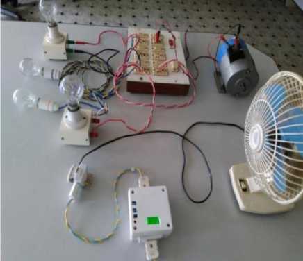
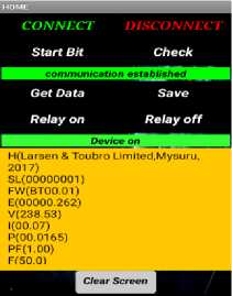
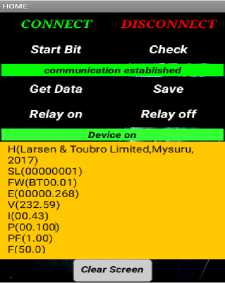
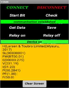
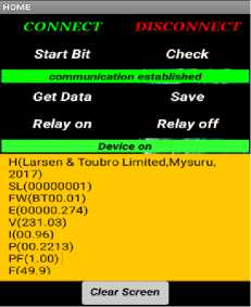
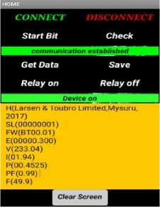
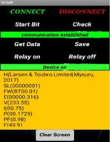
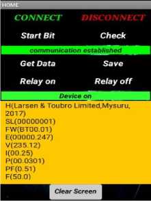
The purpose of this work is to design a product that can be plugged it into the wall socket and the load device is connected to it so that the main device will measure the power consumption of the connected device and send the same data to the android based mobile phone. The implementation result consists of designing of the hardware module for monitoring and control purpose is as shown in Fig 9. The screenshot of the application developed is shown in Fig.10
(a)
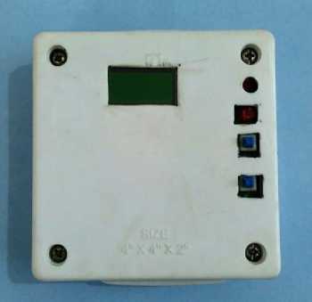
Fig.9. (a) Inside view and (b) front view of the designed product respectively
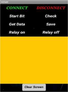
Fig.10. Home page of the application developed
Data download area
The application consists of different buttons with its own functionality i.e.
Connect : Helps to connect to the Bluetooth module by showing device list.
Disconnect: Disconnects from the Bluetooth connectivity.
Start Bit: Helps in establishing the communication between the module by sending specific command.
Check: Once communication is established next handshaking of the signal are done through this button.
Get data: Data gets downloaded from the memory to the application download area.
Save: Helps in saving the downloaded data in phone memory.
Relay on and off buttons: Sends on and off commands through an application.
Clear screen: Erases the data download area in one touch .
The overall system flow diagram is shown in the Fig 11.
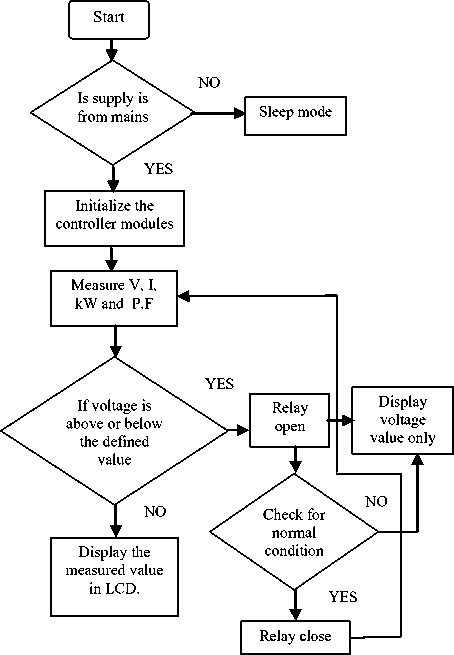
(a)
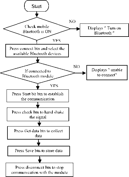
(b)
Fig.11. Flowcharts of (a) hardware module working and (b) application Working flowchart
-
VII. Results
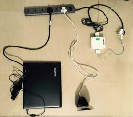
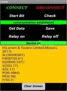
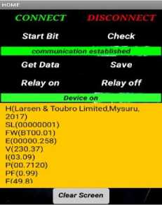
The outcome of the work consists of two main parts i.e. the monitoring of the load devices and getting the parameters like voltage, current, power, power factor and frequency and the controlling part includes relay control using android application. The setup is made in such a way that the one end of the designed product is connected to the socket and another end is connected to the load. The controlling and monitoring of the device is done using an application which is installed on the mobile.
(a)
Design and Development of a Smart Device for Energy Monitoring and Control of
Domestic Appliances: An Android Application
(b)
Fig.12. (a) The combination of loads like lamps, motor and fan setup.(b) Iron box and laptop combinations setup.
The actual power and measured power values are in close agreement. This can be explained by calculating the % error as given in equation (6)
% Error = ^- *100 (6)
Where,
A=Power calculated theoretically B= Power measured by the system.
Form the Table.1 the % Error for motor load is 3.3, for lamps and motor load combination is 1.1. This shows that the % Error is in tolerable limit.
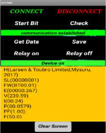
The screenshot of the result obtained by the smart phone is shown below.
The hardware module is designed and tested for different devices and got various results. For testing purpose bulbs of different watts, fan, motor iron box, laptop and also a combination of loads is also used and tested. The module setup for different loads is shown in Fig.12. accordingly, the readings are tabulated in Table.1
18W lamp
60W lamp
Table 1. Shows the monitored data for different loads
|
LOADS |
Measured and indicated value |
||||
|
Voltage (V) |
Current (A) |
Power (W) |
Power Factor |
Frequen cy (Hz) |
|
|
18W lamp |
238.53 |
0.07 |
16.5 |
1 |
50 |
|
60W lamp |
239.59 |
0.24 |
57.9 |
1 |
49.9 |
|
100W lamp |
232.58 |
0.43 |
100.0 |
1 |
50 |
|
Two 60W +one 100W lamps Total : 220W |
231.03 |
0.96 |
221.3 |
1 |
49.9 |
|
Three 60W+ one 100W lamps Total: 280W |
231.19 |
1.23 |
284.1 |
1 |
50 |
|
Three 60W+ one 100W lamps + motor(1/4HP,0.9 6P.F) Total: 457.86W |
233.04 |
1.94 |
452.5 |
0.99 |
49.9 |
|
Motor(1/4 HP) 178.8W |
233.55 |
0.75 |
172.9 |
0.98 |
49.9 |
|
Fan 40W |
232.13 |
0.30 |
37.5 |
0.53 |
49.9 |
|
Fan+ Motor 218.8W |
231.16 |
1.0 |
216.3 |
0.93 |
50 |
|
Three 60W+ one 100W lamp+ motor + fan Total: 498.8 |
233.17 |
2.17 |
498.4 |
0.98 |
50.2 |
|
Iron box 700W |
230.45 |
2.97 |
687.9 |
1 |
49.9 |
|
Laptop |
235.12 |
0.25 |
30.1 |
0.51 |
50 |
|
Iron box + laptop |
230.37 |
3.09 |
712.0 |
0.99 |
49.8 |
100W lamp
(60+60+60+100)W Lamps
(60+60+100)W lamps
(60+60+60+100)W Lamps + motor
Motor

Fan
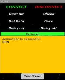
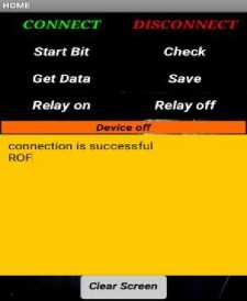
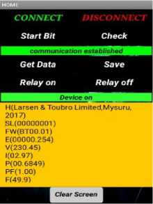
'Relay off' command sent the device, it gets disconnected from the supply and displays ROF as an acknowledgment. The screenshots of the control commands are shown in Fig.13.

Fan + motor
Fan+ motor+ lamps
(a)
(b)
Fig.13.(a) and (b) shows the load control commands sent from the app to the module.
If the relay is in ON condition, then it is easy to collect the different parameters of the connected device. If the user tries to collect the data even when the relay is in OFF condition, then he gets only the measured voltage value at that instant.
The figure 14 shows the screenshot of the result obtained when the relay is in OFF condition
Laptop
Iron box
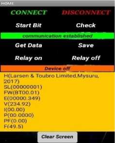
Fig.14. Result obtained when relay is in OFF condition.
Laptop+ Iron box
For controlling the load device a relay is used. This works according to the commands sent from the application. If we send 'Relay on' command the load device will get turn on with an acknowledgment RON. If
Table 2. The comparison between existing and proposed system
|
Parameters |
Existing System |
Proposed System |
|
Wireless technology used |
GPRS[1], WiFi[3], Zigbee[5][6][7] |
BLE with dual mode |
|
Data collection through |
Server[7][5] |
Mobile application |
|
Internet requirement |
Required |
Not required |
|
Cost |
More |
Less |
|
ADC Resolution type |
10 bit[5] |
24 bit |
|
Control of home appliances |
Triac [6][8] |
Relay |
|
Microcontroller |
AVR, 8bit[9] |
Renesas,16bit |
|
Current measurement |
Transformers[8] |
Shunt resistors |
|
Application development tool |
Eddycasa [9] |
MIT App Inventor |
The comparison between existing system and proposed system is shown in the Table.2
The detailed discussion for each of the parameters used for comparison is given below.
Wireless technology used:
In [1] there is a requirement of mobile data and proper signal to establish the communication with the system.
In[3] WiFi technology is used, which is costly because of the requirement of a router.
In [5][6][7] Zigbee is used for communication and there is a requirement of data aggregation before transmitting the measured data.
In the proposed system Bluetooth low energy with dual mode module is used, which consumes less power, costs less and safe for home automation.
Data collection:
In [7][5] there is a requirement of PC to collect the data and installation cost is more.
In the proposed system data is collected through mobile app and data can be easily collected from any place since it is portable.
Internet requirement:
In the existing system, there is a requirement of the internet because of WiFi, Zigbee modules.
In the proposed system internet is not required since it uses an inbuilt mobile Bluetooth for communication.
Cost:
Due to the use of technologies like GPRS, Zigbee and PLC the installation cost high.
In the proposed system the cost of the module is less as compared to other technologies.
ADC resolution type:
In [9] 10bit ADC is used, which gives less precision as compared to 24bit ADC which is used in the proposed system.
Control of home appliances:
In [6][8] Triac is used to control the devices but this produces harmonic distortion in the device.
In the proposed system a relay is used to control the device which is more efficient and safe to use.
Microcontroller used:
In [9] AVR 8bit controller is used which has less processing speed compared to a 16bit controller used in the proposed system.
Current measurement:
In [8] CT is used to measure the current which requires a larger area, costly and gives less accuracy. In the proposed system shunt resistors are used which helps to overcome the problems in CT.
Application development tool:
In [9] Eddycasa application tool is used for monitoring the instantaneous data. In the proposed system MIT app inventor is used which is user-friendly and flexible in building an app.
-
VIII. Conclusion And Future Scope
A Smart device is designed and tested for monitoring and controlling the load device using a Bluetooth module. The proposed system helps the end user to interact with the home devices and get the power consumption details in real time and can also remote control the connected device by simply sending the command through the application through a Smartphone. So the system gives the knowledge about the power consumption details and it motivates people to save energy for future use.
In future different technologies like IOT and Zigbee can be implemented in place of Bluetooth technology to monitor and control the devices. Future more features to the system can be implemented like setting the parameters with upper voltage, lower voltage and overcurrent limit which gives added safety to the system.
Acknowledgment
The authors thank the Principal, Professors, all technical staff of Electronics and Communication department of Sri Jayachamarajendra College of Engineering, Mysuru, Karnataka, India for their support in completing this work. Further authors also thank the Larsen and Toubro Limited for technical support in carrying this work.
References Design and development of a smart device for energy monitoring and control of domestic appliances: an android application
- L. V. Didhe, Prof. S.V.Kulkarni and Dr. J.W.Bakal "Remote Monitoring and Control of Home Devices using Android Platform”, International Journal of Advanced Research in Computer Science and Software Engineering, Volume 5, Issue 3, pp. 303-306 March 2015
- Moonok Choi, Jinsoo Han and Ilwoo Lee "An Efficient Energy Monitoring Method Based on Bluetooth Low Energy" , 2016 IEEE International Conference on Consumer Electronics (ICCE), 978-1-4673-8364-6/16/$31.00 ©2016 IEEE
- Ajay Sharma, Asim Verma and Monika Bhalla"Wi-Fi Home Energy Monitoring System", 2016 international conference on information technology(InCITe), 978-1-5090-2612-8/16/$31.00©2016IEEE.
- Igor Horvat, Nikola Lukac, Roman Pavlovic and Dusan Starcevic "Smart Plug solution based on Bluetooth Low Energy", 2015 IEEE 5th International Conference on Consumer Electronics Berlin (ICCE-Berlin), 978-1-4799-8748-1/15/$31.00©2015IEEE
- Maytham S. Ahmed, Azah Mohamed, Raad Z. Homod , Hussain Shareef, Ahmad H. Sabry and khairuddin bin khalid “Smart Plug Prototype for Monitoring Electrical Appliances in Home Energy Management System”, 2015 IEEE Student Conference on Research and Development (SCOReD), 978-1-4673-9572-4/15/$31.00 ©2015 IEEE
- Onur ELMA, Uğur Savaş SELAMOĞULLARI, “A Home Energy Management Algorithm with Smart Plug for Maximized Customer Comfort”, 978-1-4673-9130-6/15/$31.00 ©2015 IEEE.
- Jinsoo Han, Chang-Sic Choi, Wan-Ki Park, Ilwoo Lee, and Sang-Ha Kim. ”Smart Home Energy Management System Including Renewable Energy Based on Zigbee and PLC” , IEEE Transactions on Consumer Electronics, Vol. 60, No. 2, May 2014
- Nagender Kumar Suryadevara, Student Member, IEEE, Subhas Chandra Mukhopadhyay, Fellow, IEEE, Sean Dieter Tebje Kelly, and Satinder Pal Singh Gill. ”WSN-Based Smart Sensors and Actuator for Power Management in Intelligent Buildings” , IEEE/ASME Transactions On Mechatronics February 2014
- T. Gabriele , L. Pantoli, V. Stornelli, D. Chiulli, M. Muttillo. " Smart Power Management System For Home Appliances And Wellness Based On Wireless Sensors Network And Mobile Technology", 2015 XVIII AISEM Annual Conference, 978-1-4799-8591-3/15/$31.00 ©2015 IEEE.
- Edwin Chobot, Daniel Newby, Renee Chandler, Nusaybah Abu-Mulaweh, Chao Chen, Carlos Pomalaza-Ráez, " Design and implementation of a wireless sensor and actuator network for energy measurement and control at home", International Journal of Embedded Systems and Applications (IJESA) Vol.3, No.1, March 2013.
- Mustafijur Rahman, A.H.M Zadidul Karim, Sultanur Nyeem, Faisal Khan, Golam Matin,"Microcontroller Based Home Security and Load Controlling Using Gsm Technology", IJCNIS, vol.7, no.4, pp.29-36, 2015.DOI: 10.5815/ijcnis.2015.04.04
- Salihu Aliyu, Abdulazeez Yusuf, Umar Abdullahi, Mustapha Hafiz, Lukman A. Ajao,"Development of a Low-Cost GSM-Bluetooth Home Automation System", International Journal of Intelligent Systems and Applications(IJISA), Vol.9, No.8, pp.41-50, 2017. DOI: 10.5815/ijisa.2017.08.05
- M. Muntasir Rahman1, Md. Aktaruzzaman, Mst. Ashrafunnahar Hena, "Design and Development of a Simple Low-cost Touchscreen to Control Home Automation System", I.J. Information Technology and Computer Science, DOI: 10.5815/ijitcs.2012.11.04
