Design and Development of PC Based Data Acquisition System for Radiation Measurement

Author: M. A. A. Mashud, Md. Shamim Hossain, M. Nurul Islam, Md. Serajul Islam
Journal: International Journal of Image, Graphics and Signal Processing(IJIGSP) @ijigsp
Article in issue: 7 vol.5, 2013.
Free access
A PC based data acquisition was designed and developed using GM detector and a programmable microcontroller 16F876 of PIC family. This unit was calibrated with the standard Canberra Counter. It gave prompt response directly and has low power consumption. It was tested for gamma ray measurement to continuously monitor a radiological resulting from the natural and man-made sources that threat site security and human health. The system was simple to use, required no additional hardware and allows the selection of data. The collected data were easily being exported to a PC via parallel port. A "C" language program was developed to control the function of the entire system, using PCWH compiler.
Γ-ray, Microcontroller, LTP1 port, GM tube, PCWH compiler
Short address: https://sciup.org/15013012
IDR: 15013012
Text of the scientific article Design and Development of PC Based Data Acquisition System for Radiation Measurement
Published Online June 2013 in MECS
The emission and propagation of energy through space and/or through a material medium in the form of waves or, by extension, corpuscular emission is known as radiation. Ionizing radiation is harmful to living organs as it was realized very early in the twenty century, when accidents began to occur with radioactive sources used in research and medicine. Ionizing radiation, and radioactive substances are natural and permanent features of the environment, and the risks associated with radiation exposure can there only be restricted, not eliminated entirely. It is an unavoidable part of human life which has been existing from the beginning of this universe. Human, animals and plants have exposed to natural radiation since the creation of life. Both in the private and public sectors sealed and unsealed sources of radioactive materials and ionizing radiation are being used. Radiation energy absorbed in living tissues initiates physical and chemical reactions that may result in biological changes.
The ability to detect and measure radiation dose is of great importance, and necessitates the use of sensitive and accurate devices for these functions. It is therefore imperative to explore detection strategies. For radiation monitoring in risk involved area a portable radiation survey meter has been designed in year 1988 that explained in M.S. Islam et.al, [1]. This system is slow and designed in transistor based. For better performance another device has been developed to measure the radiation in year 1989 which explained in S. Islam et.al, [2]. The operation speed of this device is better but it is combination of transistor and ICs module. A data logger system using the Anderson current loop [3] to measure the effect of Gamma radiation exposure on thick film Nickel Oxide radiation sensors is explained in K. Arshad et.al, [4]. In year 2011 another attractive device has been developed for radiation measurement which explained in M.A.A. Mashud et.al, [5]. In this design all transistors and ICs has been replaced by using a programmable microcontroller. This system is an on device display However; this system is complex in nature which involves fabrication processes.
Now we have designed an attractive approach: PC based data acquisition system using a single chip microcontroller by which researchers and workers can monitoring the status of the radiation levels by the computer display unit.
This remainder of the paper is organized as follows: The design consideration of this system is describes in section II. In section III describes the flowchart of the computer program. After that in section IV describes the simulation results and finally we draw our conclusion in the last section.
-
II. Design consideration
The system is divided into four main parts: low voltage power supply, high voltage power supply, detector and microcontroller unit. In this unit, an alternating voltage (220V) was applied at the input of the step-down transformer that gave 9V output which was further feed to four diodes 1N 4001(A Bridge Rectifier) which gave 9V DC output that was made ripple free by use of filter capacitors. The majority of components required 5V DC for their operation. For this purpose, LM 7805 (3-terminal voltage regulator) was employed that converted 9V DC into 5V DC. In this way, all components needing 5V for their operation were connected to the output of the IC 7805. This voltage was feed at pin 20 of the PIC16F876 microcontroller as a supply voltage. The block diagram and the complete circuit diagram of the developed system are shown in Fig. 1 and Fig. 2 respectively.
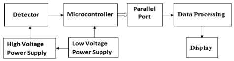
Fig. 1: Block diagram of the developed system.
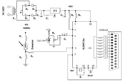
Fig.2: Complete circuit diagram of the developed system
-
A. Low voltage power supply
The low-voltage power supply circuit consists of transformer X 1 , D 1 , D 2 , D 3 , D 4 , C 1 , C 2 and IC1 [6]. The output of the IC1 is +5V dc. The capacitor C 2 is connected across the output of IC1 to eliminate the high frequency noise .
-
B. High voltage power supply
Nearly all radiation detectors require an external high voltage for their proper operation. Commonly used gamma radiation detector GM Tube requires voltage about 250V-1500V dc for their operation. The detector used in this design requires +575 V dc [7]
-
C. Detector
Detector Operating Characteristics
Detector: ZP1321 Halogen-quenched counter [8] Dose rate range: 3x10⁻³ to 102 mGy/h
Starting Voltage: 380V
Plateau Threshold Voltage: 500V
Plateau Length: 150V
Recommended Supply Voltage: 575V
Background: 12 counts/min
Dead Time: 55μS
Life Expectancy at 25 ᵒ C: 5x10¹⁰ counts
-
D. The Microcontroller (PIC 16F876)
This powerful (200 nanosecond instruction execution) and easy-to-program (only 35 single word instructions) CMOS FLASH-based 8-bit microcontroller packs Microchip’s powerful Programmable Interface Controller (PIC) architecture into a 28-pin package and is compatible with the PIC16C5X, PIC12CXXX and PIC16C7X devices [9,10]. The PIC's Console Command Processor (CCP) which is capture/compare/pulse-width module can also detect rising or falling edges every four or 16 pulses [11]. PIC16F876 features 256 bytes of electrically erasable programmable read-only memory (EEPROM) data memory, self-programming, 5 channels of 10-bit Analog-to-Digital (A/D) converter, 2 additional timers, 2 capture/compare/PWM functions, the synchronous serial port can be configured as either 3-wire Serial Peripheral Interface (SPI) or the 2-wire InterIntegrated Circuit (IIC) bus and a Universal Asynchronous Receiver Transmitter (USART). All of these features make it ideal for an advanced level A/D applications in automotive, industrial appliances and consumer applications.
Features
-
• High-Performance RISC CPU
-
• Only 35 single word instructions to learn
-
• All instructions are single cycle (1μs) except for program branches
-
• Operating speed: DC - 20MHz clock input
-
• 8 k Bytes Flash Program Memory
-
• 368 Byte RAM Data Memory
-
• 256 Byte EEPROM Data Memory
-
• In-circuit serial programming
Peripheral Features
-
• Two 8-bit timer/counter(TMR0,TMR2) with 8-bit programmable prescalar
-
• One 16 bit timer/counter(TMR1)
-
• Two Capture, Compare, PWM module
-
• 10-bit, 5-channel Analog-to-Digital converter
-
• Synchronous Serial Port (SSP) with SPI (Master mode) and I2C (Master/Slave)
-
• Universal Synchronous Asynchronous Receiver Transmitter with 9-bit address detection
-
• Two Analog Comparators
-
• Watchdog Timer (WDT) with separate RC oscillator.
Special Microcontroller Features
-
• 100,000 erase/write cycle Enhanced FLASH
program memory
-
• 1,000,000 erase/write cycle Data EEPROM
memory typical
-
• Power saving SLEEP mode
-
• Programmable code protection
-
• Selectable Oscillator Options
-
• Self-reprogrammable under software control
CMOS Technology
-
• Low power, high speed CMOS FLASH technology
-
• Fully Static Design
-
• Low Power Consumption
-
• 22 I/O pins with individual direction control
-
• 28-pin DIP
-
E. Terminal Positive Voltage Regulators
The LM78XX series of three terminal positive regulators are available in the (transistor outline) TO-220 package which is commonly used for transistors, silicon-controlled rectifiers, and integrated circuits with several fixed output voltages, making them useful in a wide range of applications. Each type employs internal current limiting, thermal shut down and safe operating area protection, making it essentially indestructible. If adequate heat sinking is provided, they can deliver over 1A output current. Although designed primarily as fixed voltage regulators, these devices can be used with external components to obtain adjustable voltages and currents [12].
Features
-
• Output Current up to 1A
-
• Output Voltages of 5, 6, 8, 9, 10, 12, 15, 18, 24
-
• Thermal Overload Protection
-
• Short Circuit Protection
-
• Output Transistor Safe Operating Area Protection
-
F. Parallel Printer Port
The Parallel Port is used for interfacing in this design. This port allow the input of up to 9 bits or the output of 12 bits at any one given time, thus requiring minimal external circuitry to implement many simpler tasks. It's found commonly on the back of our PC as a D-Type 25 Pin female connector. The pin configuration is shown in Fig. 3.
The original IBM-PC's Parallel Printer Port had a total of 12 digital outputs and 5 digital inputs accessed via 3 consecutive 8-bit ports in the processor's I/O space [13]. 8 output pins accessed via the DATA Port, 5 input pins (one inverted) accessed via the STATUS Port, 4 output pins (three inverted) accessed via the CONTROL Port, The remaining 8 pins are grounded.
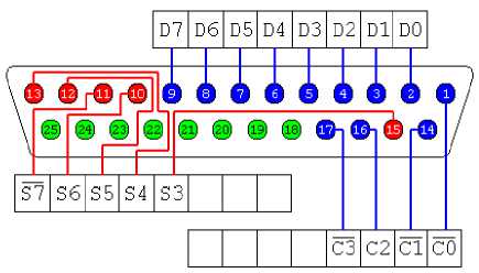
Fig. 3: Parallel printer port pin configuration[13]
There may also be a D-Type 25 pin male connector. This will be a parallel LTP1 port and thus, is a totally incompatible port.
The most common standard for interfacing with parallel printers is the Centronics parallel Interface Standard, named after the company that developed it. Centronics type printers usually have a 36-pin interface connector. The majority of the printers use this handshake. This handshake is not implemented using I/O and Packages normally. It is implemented using a Standard Parallel Port under software control [14]. A simplified diagram of the ‘Centronics’ Protocol is shown in Fig. 4.
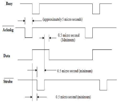
Fig. 4: Timing waveform for transfer of a data character
Data is first applied on the Parallel Port pins 2 to 7. The host then checks to see if the printer is busy i.e. the busy line should be low. The program then asserts the strobe, waits a minimum of 1uS, and then de-asserts the strobe. Data is normally read by the printer/peripheral on the rising edge of the strobe. The peripheral device indicates that it is busy processing data via the busy line. Once the printer has accepted data, it acknowledges the byte by a negative pulse about 5uS on the nAck line [14].
Quite often the host ignores the nAck line to save time. In the Extended Capabilities Port, a Fast Centronics Mode is employed, which lets the hardware do all the handshaking for the programmer. All the programmer must do is write the byte of data to the I/O port. The hardware will check to see if the peripheral device is busy, generate the strobe. This mode commonly doesn't check the nAck either.
-
III. System software
The software was divided into different sub routines and main routines [15]. To develop the system software we had used two types of programming language.
The flowchart of the microcontroller programming is depicted in Fig. 5 that shows the interaction of analog input signal and digital output signal. The compiler PCWH was used to develop the microcontroller program [16]. Assembly language is a medium of communication with a microcontroller in which the programs are written in mnemonics. Mnemonic code is a combination of letters to suggest the operation of an instruction. An assembly language is specific to a given microcontroller. As the microcontroller understands only machine code instructions, a program written in assembly language must be translated into machine language before the microcontroller is programmed.
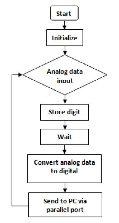
Fig. 5: Flowchart of Microcontroller Program
Software activities are those associated with the successful development and operation of a computing or processing and software is anything that drives the computer. The language used in the communication of computer instructions is known as the programming language. The computer has its own language and any communication with the computer must be in its language or translated into this language. In this section we had used programming language ‘C’ to develop the PC software. Two commands were used inportb and outportb.
The PC received the digital data through parallel printer port. At first the PC sends the acknowledgement through parallel port to microcontroller output channel and then stores the digit. The PC analyzed the digital data and converted to the corresponding decimal value for display. The developed flowchart is shown in Fig. 6. The “Turbo C” compiler was used to develop the user friendly C language program [17].
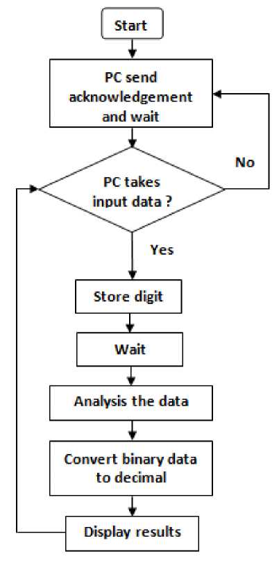
Fig. 6: Flowchart of PC Program
-
IV. Result and discussion
The system was successfully designed and developed, as its performance was strong. The system employed a local, low-cost PIC16F876 microcontroller. To avoid the complex comparator and A/D converter circuit, we used an internal comparator and A/D converter for the microcontroller. Furthermore, the internal frequency successfully avoided the external oscillator circuit. Thus the entire system function depends on the developed software. The circuit design is simple and compact.
The low voltage power supply unit was designed for highly regulated output to bias the microcontroller. In this design we had varied the input ac voltage from 198 volt to 248 volt but the output was remain constant at 5 volt DC. The output waveform of this unit is depicted in Fig. 7.
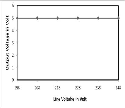
Fig 7: Output of the low-voltage power supply
The high voltage power supply unit was designed to bias the detector circuit. In this design we had produced +575V dc from 6V dc battery. The output waveform of this unit is shown in Fig. 8. From Fig. 8, it is observed that the output voltage remains constant at +575 V dc for the input variation from 6 volt to 3.2 volt
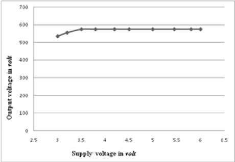
Fig 8: Output of the high-voltage unit
The detector can bias in two ways. One is common anode configuration and another is common cathode configuration. The output waveform of common anode configuration is shown in Fig.9 and the common cathode configuration is in Fig. 10.
From Fig. 9, it shows that, the negative saturation voltage is very high. If someone uses this configuration, the device can damage at a certain time due to the certain changes of voltage.
From Fig. 10, it shows that, the amplitude of positive saturation voltage is small. This changing voltage cannot damage the device. Therefore, in our design we were used common cathode configuration.
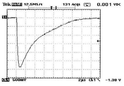
Fig 9: Output waveform of common anode configuration
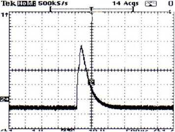
Fig 10: Output waveform of common cathode configuration
When a radiation particle enters into the detector, a voltage developed across the resistor R 2 is positive. This positive voltage is applied to the input port of the microcontroller through the current limiting resistor R 3 . This voltage signal is the analog input for the microcontroller.
The microcontroller converts this analog voltage signal into digital or binary data. The PCWH compiler was used to program the microcontroller. This microcontroller was directly interfaced with the PC through parallel port.
The famous, portable and well-known programming language turbo ‘C’ was used to design the PC software. The results were displayed on the PC monitor. For the future information the result can be record or save as a data file.
The designed data acquisition system is compared with the Function Generator shown in Table 1. The instruments underwent through tests, with satisfactory results. The system was calibrated using a radiation source from SSDL. The comparative study of linearity between CANBERA counter and developed system is depicted in Fig. 11.
Table 1: Comparison of function generator and developed system
|
Function Generator TTi, Model- TG215 |
Developed System |
|
5 Hz |
5 Hz |
|
10Hz |
10Hz |
|
15Hz |
15Hz |
|
30Hz |
30Hz |
|
50Hz |
50Hz |
|
100 Hz |
100 Hz |
|
150 Hz |
150 Hz |
|
180 Hz |
180 Hz |
|
200 Hz |
200 Hz |
|
250 Hz |
250 Hz |
|
255 Hz |
255 Hz |
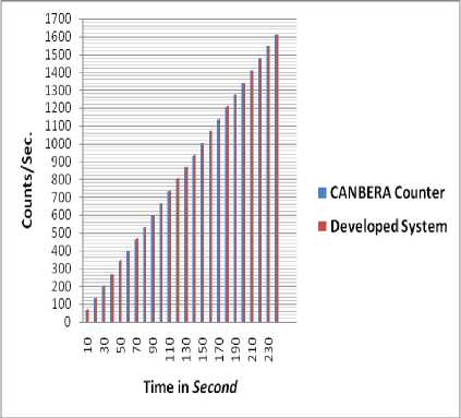
Fig. 11: Comparison of CANBERRA counter and developed system by varying the counting time
In recent times, the cost of electronic equipment has fallen significantly, though nuclear equipment remains expensive. However due to the rapid development of micro electronics, all designed components and instruments are inexpensive. Moreover, when the features of the presently used system are compared with the developed system, the latter emerges as a better choice in terms of cost, portability and design. Particularly in developing countries, the use of the deigned instruments will be accessible for many users.
-
V. Conclusion
This project has been successfully completed. The full system comprising the software and hardware have been fully implemented and tested. It provides a low cost alternative to the current commercial systems in monitoring radiation. The microcontroller makes the system very comfortable. We propose further extension to the system with added functionality such as remote sensing and controlling.
References Design and Development of PC Based Data Acquisition System for Radiation Measurement
- M.S. Islam, A.T.M.H. Rahman and S.M. Aziz, 1988, "Portable Radiation Survey Meter", Elect. Engg. Research Bulletin, ( 4), 15-22.
- S. Islam, A Kiber and M.A. Taher, 1989, "Sensitive Radiation Survey Meter", Nuclear Science and Applications, (1), 12-17.
- K. F.Anderson , 1992 "The Constant Current Loop: A New Paradigm for Resistance Signal Conditioning," NASA TM-104260.
- K. Arshak, O. Korostynska , and J. Harris, 2002 " γ- radiation dosimetry using screen printed nickel oxide thick films," in Proc. 23rd. Int. Conf. MIEL., 1, 357–360.
- M.A.A. Mashud, M.R.A.Bhuiyan, M.A Mashud & M.S. Islam, 2011, "Design and Development of Microcontroller Based Portable Digital Surface Contamination Monitor" ULAB Journal of Science and Engineering, (2), 42-46.
- B.L. Theraja, 1973 "Modern physics," S. Chand and Co. New Delhi.
- M.A.A. Mashud, M.R.A. Bhuiyan and M. S. Islam, "Design and Development of a Microcontroller Based Regulated High Voltage Power Supply for GM detectors", Journal of Jahangirnagar Physics Studies, accepted for June 2013.
- "Geiger-Muller Tubes, Data book" Centronic Limited, King Henry's Drive, New Addington. Survey, England, 1992.
- M. A. Mazidi, R.M. Kinlay & D. Causey, 2008 "PIC Microcontroller", Prentice Hall Inc., 24.
- J. B. Peatman, 1997, "Design with PIC microcontroller", Prentice Hall Inc., 2.
- "Microchip Data sheet" PIC16F876.shtml accessed on 5.8.2010.
- "Fairchild Semiconductor Data sheet" FLM7810.pdf accessed on 5.8.2010.
- http://www.doc.ic.ac.uk/~ih/doc/par.
- http://www.beyondlogic.org/spp/parallel.htm
- M.A.A. Mashud, M.A.A. Tarik, M.S. Hossain & M.S. Islam, 2012 "Design and Development of a Low-cost Microcontroller Based Single Phase Water-Pump Controller", I. J. Information Sciences and Techniques, (2) No.4, 48-56.
- PCWH Compiler®IDE version 3.43, www.ccsinfo.com
- E. Balagurushamy, 2001 "Programming in ANSI C" Tata McGraw Hill, 2nd Edition.
