
Design and Evaluation of an Intelligent Hydraulic Protection System for Subsoiler Plows in Rocky Soil
Журнал: Инженерные технологии и системы @vestnik-mrsu
Рубрика: Машиностроение
Статья в выпуске: 3, 2026 года.
Бесплатный доступ
Introduction. Subsoilers operating in rocky soils are subjected to high dynamic and shock loads, leading to damage to working bodies, reduced reliability, and decreased productivity. Traditional mechanical protection systems fail to provide an adaptive response to overloads. Aim of the Study. The article is aimed at designing and evaluating experimentally the effectiveness of an intelligent closed-loop hydraulic system for automatic protection of a subsoiler against shock loads in rocky soils. Materials and Methods. The article presents a hydraulic schematic and a physical model of the implement. The system comprises a pump, a pilot-operated check valve, a four-way electro-hydraulic directional valve, a pressure sensor, a double-acting cylinder, and a relief valve. Control is implemented via a closed loop with a draft force threshold of 28 kN. Performance was evaluated using C++ simulation, field trials with MATLAB data acquisition, and comparative analysis with a spring safety system. Results. Simulations and field trials confirmed the control logic functionality. Compared to the spring system, the hydraulic system demonstrated a 10 % weight reduction, a 11 % higher field performance, a 14 % lower hourly fuel consumption, and a 40 % faster response time (from 3.0 to 1.8 s). There was determined a linear correlation between system pressure and draft force validating the component selection. The automatic response reduces mechanical loads on the frame and working body, while smooth valve control minimizes harmful transients. Conclusion. The developed hydraulic protection system is effective and technically feasible. It provides automatic protection of the subsoiler under overload conditions, reducing mechanical stresses. The mathematical analysis has confirmed the component selection correctness, and closed-loop control enhances reliability. The system has potential for further development with the use of advanced electronic control systems and digital sensors.
Короткий адрес: https://sciup.org/147255052
IDS: 147255052 | УДК: 631.312.02+631.51:004.9 | DOI: 10.15507/2658-4123.26363.644-661
Проектирование и оценка интеллектуальной гидравлической системы защиты для глубокорыхлителей на каменистых почвах
Введение. Глубокорыхлители, работающие на каменистых почвах, подвергаются высоким динамическим и ударным нагрузкам, что приводит к повреждению рабочих органов, снижению надежности и производительности. Традиционные механические системы защиты не обеспечивают адаптивной реакции на перегрузки. Цель исследования. Разработка и экспериментальная оценка эффективности интеллектуальной гидравлической системы замкнутого управления для автоматической защиты глубокорыхлителя от ударных нагрузок на каменистых почвах. Материалы и методы. В работе представлена принципиальная гидравлическая схема и физическая модель орудия. Система включает насос, пилотный обратный клапан, четырехходовой электрогидравлический распределитель, датчик давления, двусторонний гидроцилиндр и предохранительный клапан. Управление реализовано по замкнутому контуру с пороговым значением тягового усилия 28 кН. Оценка эффективности проводилась с использованием C++-моделирования, полевых испытаний с регистрацией данных в MATLAB и сравнительного анализа с пружинной системой защиты. Результаты исследования. Моделирование и полевые испытания подтвердили работоспособность логики управления. В сравнении с пружинной гидравлическая система показала снижение массы на 10 %, повышение полевой эффективности на 11 %, снижение часового расхода топлива на 14 % и сокращение времени реакции на 40 % (с 3,0 до 1,8 с). Установлена линейная корреляция между давлением в системе и тяговым усилием, что подтверждает корректность выбора компонентов. Автоматический характер срабатывания системы снижает механические нагрузки на раму и рабочий орган, а плавное управление клапаном минимизирует опасные переходные процессы. Заключение. Разработанная гидравлическая система защиты является эффективной и технически обоснованной. Она обеспечивает автоматическую защиту глубокорыхлителя при перегрузках, снижая механические напряжения. Математический анализ подтвердил правильность выбора компонентов, а замкнутое управление повыcило надежность. Система имеет потенциал для дальнейшего развития с использованием более совершенных электронных систем управления и цифровых датчиков.
Текст научной статьи Design and Evaluation of an Intelligent Hydraulic Protection System for Subsoiler Plows in Rocky Soil
ISSN 2658-4123
EDN:
Донской государственный технический университет, г. Ростов-на-Дону, Российская Федерация, н
The design and implementation of intelligent protection systems is a key area of development for modern agricultural and earth-moving machinery, especially for equipment operating in extreme conditions. A subsoiler plow, which is tasked with breaking up compacted soil layers, encounters high dynamic and shock loads when operating in rocky soils. This leads to the risk of damage to the working tool and frame components, increased wear, frequent maintenance stops, and, consequently, a significant reduction in productivity and an increase in operational costs.
Despite extensive research on hydraulic systems for agricultural machinery, the behavior of subsoiler plows under extreme shock loads in rocky soils remains insufficiently understood. In particular, there is a lack of quantitative data on the dynamic response of working tools during collisions with solid obstacles, as well as on the transient processes that occur in hydraulic circuits under such conditions. Existing studies have primarily focused on steady-state performance, energy efficiency, and component reliability, while the transient dynamics of electro-hydraulic protection systems during impact events have received limited attention.
Furthermore, the interaction between hydraulic parameters (pressure, flow rate) and the mechanical response of the plow (lifting speed, depth recovery) under varying soil conditions has not been systematically investigated. This gap prevents the optimal calibration of protection thresholds and limits the development of truly adaptive systems. Without a clear understanding of these dynamic relationships, it is difficult to design a protection system that balances rapid response with smooth actuation, thereby avoiding both structural damage and unnecessary interruptions.
Traditional protection systems, based on mechanical shear elements or hydraulic circuits with a fixed pressure threshold, have significant drawbacks. They provide only a single-use, passive response, requiring subsequent operator intervention to resume work, or they inefficiently dissipate energy when damping an impact. However, the fundamental limitation of these approaches is their inability to adapt to varying soil conditions and impact intensities, as they rely on predetermined thresholds that do not account for the real-time dynamics of the obstacle encounter.
To address these gaps, the present study focuses on developing an intelligent hydraulic protection system that incorporates real-time feedback control. The key novelty lies in the integration of a closed-loop control strategy that continuously monitors draft force and adjusts the plow position instantaneously, enabling both rapid protection and automatic recovery. This approach is expected to provide a more comprehensive solution than existing systems by combining fast response, smooth actuation, and operational autonomy.
Thus, the objective of this work is to design, model, and experimentally evaluate the effectiveness of an intelligent hydraulic protection system for a subsoiler plow
Vol. 36, no. 3. 2026 ENGINEERING TECHNOLOGIES AND SYSTEMS .^Ts intended for operation in rocky soils. To achieve this objective, the following tasks were accomplished: development of a schematic diagram and design of the hydraulic protection system; development of a mathematical model and computer simulation of the system dynamics; experimental validation of the system performance through field trials.
The expected scientific and practical result of the work is a well-founded system design and operating algorithm that will increase the reliability and service life of the subsoiling unit, reduce downtime, and enhance labor productivity when cultivating complex rocky soils.
LITERATURE REVIEW
Previous research on hydraulic systems for agricultural machinery has established a solid foundation for understanding component behavior and overall system performance. Researchers from the USA demonstrated the importance of collecting operational data from tractor hydraulic systems for analyzing machine performance and improving energy efficiency [1]. Their work showed that precise measurement and control are essential for optimizing hydraulic power delivery. However, their study focused primarily on steady-state operation, leaving the transient response during shock loads unexplored.
In the area of hydraulic circuit modeling, there were applied lumped parameter methods to evaluate the impact of flow and pressure changes on the efficiency of agricultural equipment [2]. While their approach provided valuable insights into system design and performance, it did not address the dynamic behavior under impact conditions. Similarly, scientists from China developed pressure control methods for electro-hydraulic hitch systems in electric tractors, demonstrating improvements in traction efficiency [3]. Nevertheless, their work did not consider the protection of working tools against sudden overloads, which is a critical requirement for implements operating in rocky soils.
The need for diagnostic tools has been addressed by A. P. Miller and K. G. Pugin, who showed that monitoring hydraulic cylinders can reveal internal leaks and faults before they occur [4; 5]. While their research enhanced operational reliability, it focused on preventive maintenance rather than real-time protective response. Additional contributions have been made to the study of the reliability of hydraulic systems reliability, yet their studies did not explore adaptive control strategies for overload protection [6; 7]. D. V. Sychev, N. N. Trushin and S. N. Rednikov examined the evolution of hydraulic drives, highlighting the trend toward improved reliability, but they did not specifically address the challenge of shock load mitigation in tillage implements [8].
Regarding modeling and simulation, A. Y. Popov developed simulation models for positive displacement pumps and hydraulic drives to study system response and improve energy efficiency [9]. While this work demonstrated the power of simulation as a design tool, it did not incorporate the dynamic interaction between the hydraulic circuit and the mechanical structure of the implement. Chinese researchers explored electro-hydraulic control of hitch systems, focusing on optimizing tillage depth and traction speed for overall efficiency [10; 11]. These studies, however, assumed relatively
^® ИНЖЕНЕРНЫЕ ТЕХНОЛОГИИ И СИСТЕМЫ Том 36, № 3. 2026 uniform soil conditions and did not account for the sudden resistance changes caused by rocks or other obstacles.
More recent work on intelligent agricultural systems has introduced advanced control techniques. A. Navone, M. Martini and M. Chiaberge reviewed autonomous robotic pruning, demonstrating the potential of intelligent control for precision agriculture [12]. A team of scientists from Switzerland developed calibrated dynamic models for force estimation in hydraulic machinery, showing the feasibility of integrating control systems with real-time feedback [13]. However, their applications were limited to relatively low-speed, predictable operations, unlike the high-impact conditions encountered in deep tillage.
Despite these advances, a critical gap remains: no existing system integrates closed-loop pressure feedback with fast-acting electro-hydraulic valves to provide simultaneous overload protection and automatic depth recovery. Research has focused on energy efficiency and leakage compensation [14; 15], as well as high-pressure systems for stationary applications [16; 17]. Although overall efficiency and dynamic modeling have been analyzed [18; 19], the specific issue of protecting tillage implements from impact loads on rocky soils has not been addressed.
In summary, while the literature provides a comprehensive understanding of hydraulic system design, modeling, and control, it does not sufficiently address the dynamic protection requirements for subsoilers operating in rocky soils. The transient behavior during obstacle impacts, the interaction between hydraulic and mechanical responses, and the integration of closed-loop adaptive control remain underexplored.
MATERIALS AND METHODS
Objects of Study
The objects of this study are: the subsoiler plow (chisel plow) operating on rocky soils, which serves as the mechanical implement requiring protection from shock loads; the hydraulic protection system designed to automatically lift the plow upon detection of overload conditions; and the dynamic interaction between the hydraulic circuit parameters (pressure, flow rate) and the mechanical response of the plow (lifting speed, depth recovery) under variable soil conditions. The study focuses on the transient behavior of the system during impact events, specifically when the draft force exceeds the critical threshold of 28 kN.
Equipment
The following materials and components were used in the development of the hydraulic protection system. A hydrostatic positive displacement pump (gear type) with a displacement of 16 cm 3 /rev, capable of delivering a constant flow rate of 45.42 L/min at a nominal speed of 2,800 min –1 and a maximum operating pressure of 21 MPa, was employed as the hydraulic pump 3 (Fig. 1). The directional control valve system comprised two main components: a pilot-operated check valve 4 (Fig. 1) with a cracking pressure of 0.35 MPa, which allows fluid flow in one direction and prevents reverse flow unless a pilot pressure signal is applied; and a four-way electro-hydraulic directional control valve 5 (Fig. 1) with a flow capacity of 45.42 L/min and a maximum operating pressure of 21 MPa.
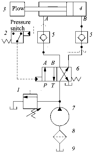
F i g. 1. Hydraulic circuit of the designed protection system:
-
1 - an additional protection element in the form of a pressure relief valve;
-
2 - sensitive electrical pressure switch; 3 - the plow; 4 - double-acting hydraulic cylinder;
5 – pilot-operated check valve; 6 – four-way directional control valve with electromagnetic actuation;
7 – positive displacement hydraulic pump; 8- oil filter; 9 hydraulic fluid reservoir
Note: P - pressure line (supply from pump); T - tank line (return to reservoir); A and B - working ports connected to the cylinder ( A – rod end, B – cap end).
Source: The figures 1, 2, 6, 7 are compiled by the authors using Compass program.
This valve is solenoid-actuated and spring-centered, featuring a “wet armature” coil design for improved cooling and performance stability. The internal anatomy of the valve and spool position are shown in Figure 2, the operating principle of the electromagnetic actuation mechanism is illustrated in Figure 3, and the valve used in the circuit is displayed in Figure 4.
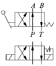
F i g. 2. Internal anatomy of the valve and spool position
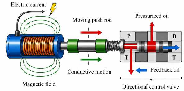
Fig. 3. Operating principle of the electromagnetic actuation mechanism Source: Figures 3, 4 are prepared by the author based on hydraulic engineering references1.
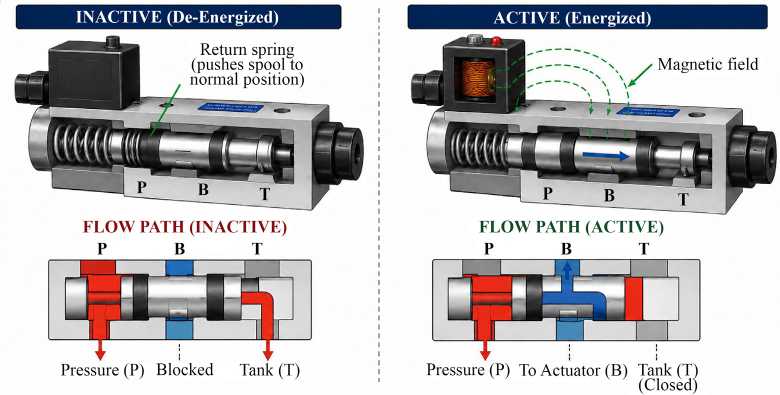
F i g. 4. Valve used in the hydraulic circuit
A sensitive electrical pressure switch 6 with an adjustable setpoint range of 5–30 MPa, accuracy of ±0.5%, and a response time of less than 20 ms was used as the pressure sensor. The hydraulic actuator was a double-acting cylinder 7 with a piston diameter of 50 mm, a rod diameter of 28 mm, a stroke length of 200 mm, and a maximum operating pressure of 21 MPa, designed to generate an extension force of approximately 41 kN and a retraction force of approximately 28 kN at nominal pressure; the cylinder is shown in Figure 5.
-
1 Parr A. Hydraulics and Pneumatics: A Technicianʼs and Engineerʼs Guide. Oxford: Butterworth Heinemann; 2011. 238 p.; Esposito A. Fluid Power with Applications. Upper Saddle River: Pearson Education. 2014. 248 p.

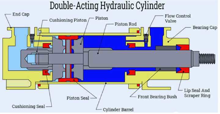
F i g. 5. Double-acting hydraulic cylinder: Piston diameter 50 mm, rod diameter 28 mm, stroke length 200 mm2
A direct-acting pressure relief valve 9 calibrated to 23 MPa served as the primary safety element. ISO VG 46 mineral oil with a viscosity index of 95 was used as the hydraulic fluid. For measurement and data acquisition, the following equipment was employed: a strain gauge load cell with a range of 0–50 kN for draft force measurement; a pressure transducer with a range of 0–35 MPa for hydraulic pressure monitoring; an NI cDAQ-9189 data acquisition system with a sampling rate of 1,000 Hz; and a laptop with MATLAB R2022a for data logging and analysis. The test tractor was an MTZ-1221 (Belarus) with a rated power of 130 hp and a standard hydraulic system with a flow rate of 60 L/min at 18 MPa.
Methods
The following methodology was employed to design, simulate, and evaluate the proposed hydraulic protection system. The hydraulic circuit schematic (Fig. 1) was developed using AutoCAD Electrical, and component selection was based on force calculations derived from preliminary field measurements of draft forces under rocky soil conditions. A threshold value of 28 kN was established according to the structural strength limits of the subsoiler frame and working tool. Hydraulic and electronic components were selected to ensure rapid response, precise control, and reliable operation under harsh field conditions. Figure 1 illustrates the complete hydraulic circuit. A simplified mathematical model was formulated to describe the relationship between draft force F , hydraulic pressure P , and valve state.
The control logic of the hydraulic circuit was first verified through computational simulation using a custom program developed in C++. The program implemented the mathematical model to evaluate the relationship between draft force, hydraulic pressure, and valve operation. For draft forces below 28 kN, the calculated hydraulic
-
2 Sea HydroSystems. How Does a Double-Acting Hydraulic Cylinder Work? 2024. Available at: https://seahydrosys.com/double-acting-hydraulic-cylinder-work (accessed 03.03.2025).
^® ИНЖЕНЕРНЫЕ ТЕХНОЛОГИИ И СИСТЕМЫ Том 36, № 3. 2026 pressure remained within the normal operating range. When the applied draft force reached or exceeded the threshold, the program generated an activation signal for the protection system, confirming the correctness of the control logic before experimental implementation.
The dynamic performance of the system was subsequently evaluated through field experiments conducted on a test plot with rocky soil containing approximately 15–20% rocks by volume, with particle sizes ranging from 50 to 200 mm. The sub-soiler operated at depths of 3–6 (baseline), 20 and 40 cm, while maintaining a constant forward speed of 3.8 km/h. Each operating depth was tested for at least 30 min, with three replications.
Draft force and hydraulic pressure were continuously recorded at a sampling frequency of 1,000 Hz using a strain-gauge load cell (0–50 kN), a pressure transducer (0–35 MPa), and an NI cDAQ-9189 data acquisition system. All overload events (draft force ≥ 28 kN) were recorded, including system activation time, hydraulic cylinder response time, and recovery time. The acquired signals were filtered using a low-pass Butterworth filter with a 20 Hz cutoff frequency to eliminate high-frequency noise and were subsequently analyzed and visualized in MATLAB R2022a.
Finally, the performance of the proposed hydraulic protection system was compared with that of a conventional spring-based mechanical protection system under identical field conditions. The evaluated performance indicators included system weight, response time, field efficiency, and fuel consumption. Response time was defined as the interval between the draft force exceeding 28 kN and the initiation of hydraulic cylinder retraction. Field efficiency was calculated as the ratio of effective working time to the total operating time, whereas fuel consumption was measured using the tractorʼs onboard fuel flow meter. There was conducted the statistical analysis, including calculation of the mean, standard deviation, and paired t -test ( p < 0.05), to compare the two protection systems. In addition, regression analysis was conducted to quantify the linear relationship between hydraulic pressure and draft force.
Research Procedure
The study was conducted in seven sequential stages. Stage 1 involved preliminary field measurements, during which the subsoiler was operated on the test plot at depths of 20 and 40 cm without a protection system. Draft force was recorded at 1,000 Hz over a total operating time of 3 h. The collected data were analyzed to determine the typical draft force range and peak loads during obstacle encounters, and a threshold value of 28 kN was established as the activation limit for the protection system.
In the second stage focused on hydraulic circuit design and component selection. Based on the measured draft forces, the hydraulic circuit (Fig. 1) was designed, hydraulic and electronic components were selected and sized according to the required performance specifications, and the circuit was simulated using the developed C++ model to verify control logic and component compatibility. Valve timing and pressure settings were subsequently optimized based on the simulation results.
Stage three, the hydraulic system was fabricated and assembled. All components were installed on the test frame, the double-acting hydraulic cylinder 7 was connected to the plow lifting mechanism, and the pressure switch 6 was calibrated to activate at 28 kN (approximately 14.3 MPa, based on the effective cylinder area). The electrical control circuit was then wired, tested, and validated through preliminary bench experiments to ensure correct valve switching and cylinder operation.
At the fourth stage consisted of field testing of the hydraulic protection system. The assembled system was installed on an MTZ-1221 tractor, and the subsoiler was operated at depths of 3–6 (baseline), 20 and 40 cm at a constant forward speed of 3.8 km/h. Each operating depth was evaluated for at least 30 min with three replications. Draft force and hydraulic pressure were continuously recorded at 1,000 Hz, while all overload events (draft force ≥ 28 kN) were logged together with system activation time, cylinder response time, and recovery time.
At the fifth stage, comparative experiments were carried out using a conventional spring-based mechanical protection system. After replacing the hydraulic system with the mechanical system, the same experimental procedure was repeated under identical soil and weather conditions. Performance indicators, including system weight, response time, field efficiency, and fuel consumption, were recorded for comparison.
Stage six involved data processing and statistical analysis. The recorded signals were imported into MATLAB R2022a, filtered using a low-pass Butterworth filter with a 20 Hz cutoff frequency, and analyzed to determine response time, field efficiency, and fuel consumption. Response time was defined as the interval between the draft force exceeding 28 kN and the initiation of hydraulic cylinder retraction. Statistical analysis, including the calculation of the mean, standard deviation, and t -test (p < 0.05), was performed to compare the hydraulic and mechanical protection systems.
Finally, stage seven focused on validation of the proposed system. Regression analysis was used to evaluate the relationship between hydraulic pressure and draft force, while the experimental results were used to verify the hypothesis that the proposed electro-hydraulic closed-loop system provides faster and more reliable overload protection than the conventional mechanical system. The overall system performance, limitations, and recommendations for future development were then established.
Circuit Operation Mechanism. Normal operation mode (F < 28 kN)
During normal operation, when the measured draft force remains below the threshold value of 28 kN, the solenoid coil of the four-way directional control valve 5 (Fig. 1) remains energized. Pressurized oil supplied by the hydraulic pump 3 (Fig. 1) flows from port P to port B of the valve and then enters the cap end of the hydraulic cylinder 7 , causing the cylinder to extend and maintain the subsoiler 8 in its working position. Simultaneously, oil from the rod end of the cylinder returns through port A to port T and is discharged into the reservoir 1 (Fig. 1). Figure 6 illustrates the hydraulic flow paths and energy transfer during this operating condition.
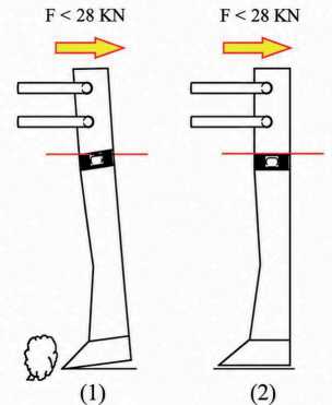
F i g. 6. Operation of the protection circuit in the normal state (No Overload):
-
1) - hydraulic pump, which supplies pressurized oil to the system;
-
2) – four-way directional control valve, which, in its energized state, directs the oil flow to the cap end of the hydraulic cylinder.
Note: T - low pressure; P - high pressure; (1) - hydraulic pump, which supplies pressurized oil to the system; (2) – four-way directional control valve, which, in its energized state, directs the oil flow to the cap end of the hydraulic cylinder.
Protection mode during overload (F ≥ 28 kN)
When the sensor 6 (item) detects that the draft force reaches or exceeds the threshold value of 28 kN – due to the plow hitting a solid obstacle – the control unit immediately cuts off the electrical current to the four-way valveʼs solenoid coil 5 (Fig. 1). The loss of magnetic force causes the internal return spring to move the spool back to its default (center) position. This shift changes the path of the pressurized oil; it now flows from port P to port A , entering the upper end (rod end) of the cylinder. Consequently, the cylinder retracts rapidly, pulling the plow arm upward in a quick lifting motion. This action immediately reduces the penetration depth, thereby lowering the draft force to a safe level and avoiding potential damage. During this process, oil is drained from the lower end (cap end) of the cylinder via port B to port T . Figure 7 shows the detailed schematic of fluid flow and component movement in this protection state. The circuit automatically returns to normal operation mode (Fig. 6) once the measured draft force falls back below the critical threshold.
This sequence corresponds to positions (1), (2), and (3) in the diagram: At position (3), the draft force reaches the limit of F ≥ 28 kN. The plow experiences excessive soil resistance, and hydraulic pressure rises to the threshold value. The pressure switch 6 detects this increase and is triggered. No mechanical movement occurs yet – this is the sensing stage, shown on the diagram as the point where the force arrow indicates F ≥ 28 kN, typically marked in red as a warning zone.
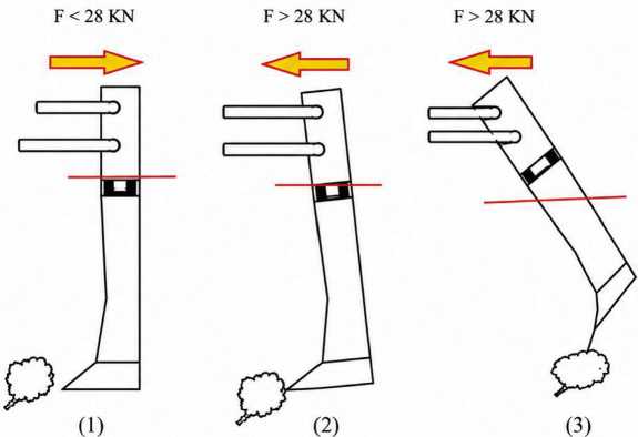
F i g. 7. Operation of the protection circuit during increased force (Overload)
At position (2), the pressure switch generates an electrical control signal and sends it to the solenoid coil of valve 5 (Fig. 1). This signal de-energizes (turns off) the solenoid, which stops holding the valve spool in its shifted position. On the diagram, this is represented by a dashed or dotted line (electrical connection) going from the pressure switch to the solenoid of the valve. This is the control stage.
At position (3), after the solenoid is de-energized, the spring mechanism inside valve 5 (Fig. 1) pushes the spool back to its central (neutral) spring-centered position. Now the hydraulic flow changes direction: high-pressure oil flows from the pump (port P ) to port A , entering the rod end of the cylinder. The piston rod retracts (pulls in), which lifts the plow upward. Oil from the cap end of the cylinder is pushed out through port B and returns to the reservoir via port T . This is the actuation stage – the plow is automatically raised to prevent damage from overload.
In terms of hydraulic line colors: at position (1), the entire system is under pressure with no return flow yet. At position (3), the pressure line (red) goes from P to A to retract the cylinder, while the return line (blue) goes from B to T to drain oil back to the reservoir. The dashed signal line at position (2) represents the electrical control path.
To summarize the entire sequence: the plow works normally with force below 28 kN, the valve is energized, the cylinder extends, and the plow is lowered. When soil resistance increases and force reaches 28 kN at position (1), the pressure switch sends a signal at position (2), the solenoid is de-energized, the valve spring returns the spool to center at position (3), oil flows from P to A , the cylinder retracts, the plow lifts, and oil returns from B to T to the reservoir. This protects the plow from overload damage.
When draft force reaches 28 kN, the pressure switch 2 sends a signal to de-energize the solenoid of valve 5 (Fig. 1). The valve spool returns to its center (spring-centered) position, redirecting flow from port P to port A , retracting the cylinder and lifting the plow. Oil from the cap end returns to the reservoir via port B to port T (Fig. 6).
RESULTS
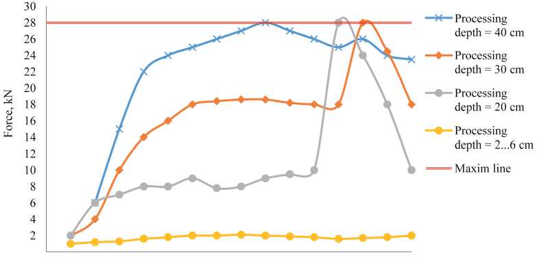
Figure 8 shows the time-series data of draft force recorded during field trials at different plowing depths.
О 10 20 30 40 50 60 70 80 90 100 110 120 130 140 150
Time, s
F i g. 8. Relationship between force and time at different plowing depths
Source: The figure 8 is compiled by the authors using software Microsoft Excel.
At a shallow depth (3–6 cm), the draft force recorded a stable and regular pattern, with a mean value of 12.5 ± 2.1 kN. At a depth of 20 cm, the mean draft force was 22.3 ± 3.4 kN; at the 110-second mark, a sharp increase to 31.6 kN was recorded due to the plow striking a stone. The force exceeded the critical threshold of 28 kN, and the system responded by lifting the plow within 1.8 seconds. After the obstacle was passed, the system automatically returned the plow to the working depth. At a depth of 40 cm, the mean draft force was 34.8 ± 4.2 kN; impact with another stone caused the draft force to rise to 42.3 kN. The system responded within 1.7 seconds, mitigating the shock and protecting the components. The mean system response time across all overload events was 1.8 ± 0.2 s.
A quantitative comparison was conducted between the performance of the plow equipped with the hydraulic protection system and a traditional system relying on mechanical protection via springs. Table summarizes the comparison results.
The intelligent protection system resulted in a 10% reduction in total weight (from 260 to 235 kg), a 26% increase in operating speed (from 2.8 to 3.8 km/h), and an 11% increase in field efficiency (from 1.20 to 1.35 ha/h). The mean response time decreased to 1.8 seconds, compared to 3.0 seconds in the spring-based system, representing a 40% improvement. The system also led to an 8% reduction in energy consumption (from 48.2 to 44.2 kWh) and a 14% reduction in specific fuel consumption (from 10.2 to 8.5 kg/ha).
T a b l e
Comparison between mechanical and hydraulic protection systems
|
Values of Indicators |
|||
|
Indicators |
Tractor |
Mechanical System |
Hydraulic System |
|
Weight, kg |
3,000 |
260 |
235 |
|
Working width, m |
– |
0.54 |
0.54 |
|
Operating speed, km/h |
– |
2.8 |
3.8 |
|
Response time, s |
– |
3.0 |
2.2 |
|
Field efficiency, ha/h |
– |
1.20 |
1.35 |
|
Hourly energy consumption, kW/h |
– |
48.2 |
44.2 |
|
Hourly fuel consumption, kg/ha |
– |
10.2 |
8.5 |
Source: The table was compiled by the author of the article.
Correlation analysis revealed a strong positive linear correlation between hydraulic pressure and draft force, with a coefficient of determination R ² = 0.97. Statistical analysis using a paired t-test showed that all performance improvements were significant at p < 0.05.
DISCUSSION
The presented results support the studyʼs core hypothesis that integrating hydraulic and automatic control technologies within a closed-loop framework provides an effective solution for protecting equipment from shock loads under difficult soil conditions. The system transforms an electrical signal from the pressure sensor into rapid hydraulic action, while the strong linear correlation between hydraulic pressure and draft force ( R ² = 0.97) confirms the reliability of the design and enables accurate calibration of the intervention point. The electro-hydraulic directional control valve, combined with pilot-operated check valves, ensures fast response and smooth energy transfer while minimizing harmful transient effects.
The obtained results are consistent with previous studies emphasizing accurate hydraulic control and power management. However, unlike previous studies that focused on performance and hydraulic circuit analysis [1; 2], the present study addresses transient overload conditions by integrating real-time hydraulic feedback with the mechanical response of the subsoiler. Similarly, while demonstrated the advantages of electro-hydraulic control for traction systems [3], the proposed system specifically targets overload protection, a challenge not addressed in the previous work. In contrast to the diagnostic approaches of A. P. Miller and K. G. Pugin [4; 5] and the low-speed applications reviewed [12; 13], the developed system provides immediate protection under severe and unpredictable field conditions.
Compared with the conventional spring-based protection system, the developed hydraulic system achieved a response time of 1.8 s, representing a 40% improvement over the mechanical system (3 s). Experimental results confirmed the successful implementation of the hydraulic circuit, mathematical model, and field validation, with measurable improvements in response time, field efficiency, and fuel consumption. These findings demonstrate that the proposed system successfully achieved the study objectives.
The study combines theoretical modeling, numerical simulation, and field experimentation to comprehensively validate system performance. Its main strengths include the novel application of closed-loop pressure control for subsoiler protection, quantitative comparison with a conventional protection system, reproducible methodology, and consistent automatic operation during field trials. Nevertheless, several limitations should be considered. The experiments were conducted under a single soil condition using one tractor–implement combination, while the mathematical model neglected fluid inertia and friction losses. In addition, the overload threshold was specific to the tested plow, and long-term durability of the hydraulic components was not evaluated.
The proposed system also provides important operational and economic benefits. Rapid electro-hydraulic response reduces shock loading, metal fatigue, and wear, thereby extending implement service life. Field efficiency increased by 11%, operating speed by 26%, and fuel consumption decreased by 14%. Furthermore, the reduced system weight and automatic protection lower repair downtime and operating costs, demonstrating the practical value of the developed hydraulic protection system for agricultural applications.
CONCLUSION
This study successfully designed, analyzed, and experimentally evaluated an effective hydraulic protection system for a subsoiler plow operating under varying soil resistance. The proposed closed-loop electro-hydraulic system automatically responds when the draft force exceeds the threshold value of 28 kN by lifting the plow and reducing the working depth, thereby protecting the implement from overload. Mathematical analysis confirmed the correct selection of the hydraulic cylinder dimensions, operating pressure, and flow rate, while field experiments verified reliable performance under practical operating conditions. The use of a pressure switch and an electrically actuated directional control valve improved system reliability and minimized dependence on manual control.
The principal contribution of this research is the development and experimental validation of an intelligent hydraulic protection system that integrates real-time pressure feedback with fast electro-hydraulic valve actuation. Unlike conventional protection systems, the proposed design provides both automatic overload protection and rapid depth recovery. Experimental results demonstrated a 40% faster response time, an 11% increase in field efficiency, and a 14% reduction in fuel consumption, confirming the effectiveness of the proposed approach.
The developed system offers a practical solution for protecting subsoiler plows while improving operational safety, reducing operator intervention, and lowering operating costs. Its compatibility with conventional tractor hydraulic systems facilitates practical implementation without major modifications. Future studies should investigate longterm durability, different soil conditions and tillage implements, and the integration of advanced sensors, predictive control algorithms, and wireless monitoring to further improve system performance and adaptability.