Design and Implementation of a Power Efficient Pulse-shaping Finite Impulse Response Filter on a Field Programmable Gate Array Chip

Author: Puja Kumari, Rajeev Gupta, Abhijit Chandra
Journal: International Journal of Image, Graphics and Signal Processing(IJIGSP) @ijigsp
Article in issue: 4 vol.4, 2012.
Free access
This paper presents one novel algorithm for minimization of non-zero coefficients of Finite Impulse response (FIR) pulse-shaping filter, mostly employed in practical digital communication system to alleviate the difficulties resulting from Inter Symbol Interference (ISI), followed by its hardware optimization on a Field Programmable Gate Array (FPGA) chip . Filter performance has been demonstrated through the inclusion of impulse response, magnitude spectrum and requirement of various hardware blocks. The supremacy of our algorithm has been substantiated by comparing its performance with other existing models of different length. From the simulation results, it has been concluded that the proposed FIR filter provides a considerable reduction in the number of non-zero coefficients without affecting its performance significantly.
Finite Impulse Response (FIR) filter, Power efficiency, Pulse-shaping filter, Raised Cosine (RC) filter
Short address: https://sciup.org/15012288
IDR: 15012288
Text of the scientific article Design and Implementation of a Power Efficient Pulse-shaping Finite Impulse Response Filter on a Field Programmable Gate Array Chip
Published Online May 2012 in MECS DOI: 10.5815/ijigsp.2012.04.01
through the use of multiply and accumulate (MAC) algorithms in special DSP devices [6]. Fig. 1 below shows how MAC architecture is implemented through N multiplications, N delays and (N-1) additions for obtaining each output sample.
Fig. 1 MAC FIR Filter Block Diagram
Due to the stringent demand for high speed data transmission, higher order FIR filters have frequently been applied for performing adaptive pulse shaping and signal equalization on the received data [7]. Hence, minimization of computational complexity, processing delay, hardware cost becomes just about inevitable in the design task of FIR filter. As obvious, all of these parameters are direct function of the number of multipliers and adders used in filter realization [8] and hence reduction of the filter tap coefficients is of paramount significance to the researchers of late.
In connection to this demand, an algorithm has been proposed in [9] to modify the values and number of non–zero coefficients of digital FIR pulse-shaping filter. The concerned algorithm reduces the arithmetic complexity, power consumption, area usage and processing time needed to obtain the filter output. The efficiency of the algorithm has been enhanced when it has been integrated with Distributed Arithmetic (DA) [10] algorithm in the design of higher order digital FIR filters. With the incorporation of the proposed algorithm, the FIR filter has been represented with a number of non-zero coefficients that is half of the number of the original coefficients. But the resulting bit error rate (BER) in a CDMA system has been the same as in the case when the filter with original coefficients is used.
Recently an efficient algorithm has been introduced in [11] which had noticeably minimized the non-zero coefficients of FIR pulse-shaping filter. The simulation results reveal the fact that the proposed filter performs comparably in a Quadrature Phase Shift Keying (QPSK) modulated system in terms of resulting BER values as compared to standard RC filter.
In this paper, one novel algorithm has been proposed to minimize the number of non-zero coefficients of standard RC FIR pulse-shaping filter along with its hardware implementation. In this concern, new sets of FIR filter coefficients have been found out by using MATLAB 7.0 for seven different lengths of the filter. The performance of the filter is studied in terms of the number of coefficients derived, frequency spectrum and the percentage of transmitted signal’s average power as compared to standard RC filter. These values have also been listed for algorithms proposed in [9] and [11] for the purpose of comparison. In order to have a clear idea about the requirement of hardware cost, all of these FIR architectures have been implemented using XILINX ISE Design Suite 12.3 and the corresponding experimental outcomes have also been illustrated.
-
II. theoratical background
-
A. Pulse Shaping Filter
Pulse-shaping is very much essential to limit Inter Symbol Interference (ISI) in digital or mobile communication systems. In this process, the pulse waveform is reshaped in order to lessen system ISI and thereby the system error performance is improved appreciably [12]. The operation of pulse-shaping is normally executed through a low-pass filter, called pulse-shaping filter, before the modulator block in the transmitter side. In order to ensure no ISI, the filter has to satisfy the Nyquist minimum bandwidth criterion as suggested in [2-3]. According to this criterion, the cutoff frequency of the digital filter must be equal to the half of the symbol rate which can be represented mathematically as [2-3]:
|HNyquist (e '")|={i ;; ^Nyquist < <л (1)
Where ωNyquist = ωs/2, ωs=2πfs and fs is the input symbol rate in Hz.
The minimum bandwidth Nyquist filter, as described in (1), is an ideal, brick-wall low-pass filter which shows an infinite attenuation slope in the stopband region. Thus an infinite number of filter sections are required to realize this infinite attenuation slope and consequently makes it difficult to be implemented in practice. So modern digital communication system includes practically realizable RC and RRC filters for this pulse-shaping operation.
It is obvious that quicker a pulse decays outside its interval, less likely for it to allow timing jitter between the adjacent pulses. One example of a zero-ISI pulseshape is the RC pulse, as outlined below [2]:
p(t) = sin-t ⁄ T cosnpt ⁄ T-pt= ⁄T i-4P2t2⁄ T2
Replacing t by (t-td)=(t-mT) letting t=nT and T=kT yields:
t n Ts-mkTs _ n
T==
Making this substitution, the sample sequence for 0≤n≤2m can be obtained as [2]:
sin л {( n ⁄ k ) -m } cos{(n⁄k)-m}
p[n]=
П{( ⁄k)—m} l-4p2{( ⁄k)—m }(4)
When the filter response is p[n] and the input x [ n ] = δ[n-1] then the filter output У [ n ] is represented by [14]:
У [ n ]= x [ n ]⨂ p [ n ]= p [ n -1] (5)
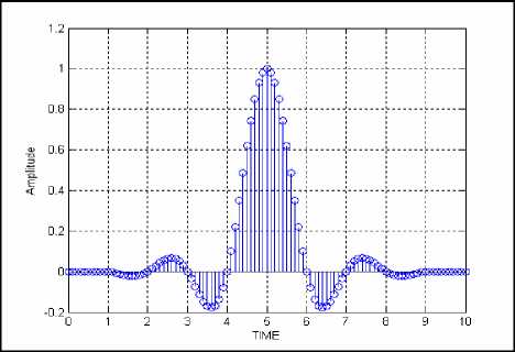
Fig. 2 Raised Cosine (RC) pulse-shaping filter
-
B. Architecture of Standard FIR Filter
FIR filters are characterized by a finite number of impulse response coefficients. The output sequence y(n) of an FIR Filter of order N-1 can simply be written as the convolution sum of the input sequence X ( n ) and the impulse response ℎ( n ) of the filter. This can be depicted mathematically as [8, 13]:
У (n)=∑к ℎ( к )․ x ( n - к ) (6)
In order to compute a particular output sample from a FIR filter of order N-1, it requires altogether N number of multiplications and (N-1) number of additions. For higher order filter, the number of coefficients in its impulse response is quite large and thus the arithmetical complexity also enhances leading to an increase in processing time in [14].
-
C. Distributed Arithmetic
An alternative to the approach as shown in Figure 1 is the Distributed Arithmetic (DA) technique which is well known method to save resources. However, using this approach the filter can be implemented in bit serial or parallel mode to trade bandwidth for area utilization. The input variable in (6) can be represented in its weighted format as:
xk = —x n,k-1 + Sm=1xn,k- 1 - m 2 (7)
Using (7) in (6) and after some mathematical manipulations the filter output given in (6) can be written as in (8):
Г = S»J>SlSjZk-1-m2-m (8)
Implementation of (8) in bit serial DA basic structure [10] will result in constructing lookup table (LUT) of size 2m where m is the number of input variables i.e. filters coefficients. This is the major drawback of the basic DA architecture which makes it sometimes impractical for designing high order FIR digital Filters.
-
III. P roposed algorithm
The main goal of the algorithm is to reduce the number of non-zero coefficients of standard RC pulseshaping filter in an efficient way so as to maintain its pass-band and stop-band behavior as closely as possible. We have implemented the entire algorithm in MATLAB 7.0 and the fundamental steps of it have been summarized below:
Algorithm PROPOSED_FILTER
Input [i] ;
Output у [i];
-
* // x[i] is the coefficients of n-length standard RC filter and y[i] is the coefficients of proposed pulseshaping filter obtained through the incorporation of the proposed algorithm //*
Begin
m [i] = ABSOLUTE (x[i]) ;
I [i] = SORT (m[i]) ;
-
* // where sorting is done in the ascending order //*
If ( - == 0 ) then
Med= {'61+ '[“1) ;
else
Med={ 'Ft] } ;
For (each x[i] ) {
MOD (x [i]) - Med = W;
If (W >= 0) then z [i] = x[i];
else z [i] = 0 ;
}
-
* // comparison has been made between the absolute value of the coefficients with the median //*
s = SUM (MOD (z[i] ));
-
* // s is the summation of the absolute value of the coefficients obtained after comparison with median // *
s
Mean = ;
n
For (each [ ] ) {
MOD (z[i]) - Mean = W;
If (W >= 0) then
w[i] = z[i] ;
else w [i] = 0 ;
}
-
* // comparison has been made between the absolute value of the coefficients with the mean //*
For (each [ ] ) { у [i] = w[i];
}
-
* // [ ] is the final coefficients of the proposed pulse shaping filter which is utilized for average signal power calculation along with the design and implementation of proposed FIR filter on a Field Programmable Gate Array (FPGA) chip //*
End
This work primarily puts an emphasis on the design of power efficient pulse-shaping filter to be used in standard digital communication systems. In regard to this, calculation of transmitted signal’s average power with respect to standard RC filter seems to have significant importance and follows the following Gaussian curve as in Fig. 3.
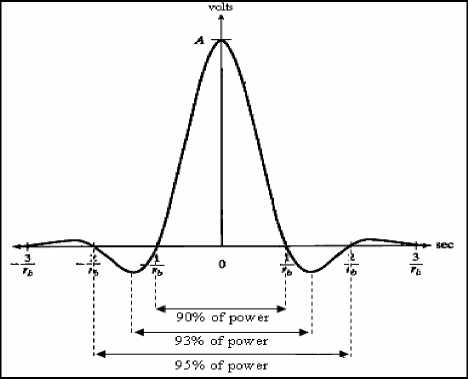
Fig. 3 Distribution of transmitted signal’s average power
-
IV. simulation results and analysis
The described algorithm, dealing with the median and mean concept, has been applied to each of the coefficients for different lengths of the filter. As a result, there is a significant reduction in the number of nonzero coefficients of low-pass FIR filter with optimized level of power transmission. Again, the impulse responses for different lengths of the filter are plotted which reveals that main lobe is present everywhere; while majority of the side lobe coefficients are absent leading to a significant reduction in coefficients with optimization of power. Now, the magnitude response of FIR filter for different lengths is plotted which demonstrates that pass-band characteristics and stopband characteristics are almost identical to that of standard RC filter and it can be efficiently applied for the practical purpose. Finally, the designed filter has been implemented on a Field Programmable Gate Array (FPGA) chip to have an idea about the hardware complexity of the proposed filter. Thus our work has been organized by reducing the non-zero coefficients with optimized power, plotting the impulse response and magnitude response of the proposed filter, followed by an analysis of hardware implementation. The detail results and its analysis are described below.
Our proposed algorithm, as described in the previous section, has been implemented using MATLAB 7.0 software and the corresponding simulation result has been presented and critically analyzed in this section. Since we are dealing with a power efficient design of pulse-shaping filter; the number of non-zero filter coefficients plays a very significant role in this regard. The numerical values of this parameter resulting with standard RC and our proposed filter have been listed in TABLE I for seven distinct lengths, namely 33, 49, 65, 81, 97, 113 and 129 with a value of roll-off factor to be 0.22. In order to prove the supremacy of our design, we have also compared our results with another recent algorithm as described in [11], aiming to solve the same problem of interest. The efficiency of the proposed pulse-shaping filter in reducing the power content can well be identified from the numerical entries of transmitted signal’s average power, as given in TABLE 2.
TABLE 1. Comparison Of The Number Of Non Zero Coefficients Of Standard RC, Chandra’S Algorithm And Proposed Filter
|
Length of the filter |
Standard RC filter |
Chandra’s filter [11] |
Proposed pulse-shaping filter |
|
33 |
29 |
13 |
11 |
|
49 |
43 |
17 |
13 |
|
65 |
57 |
23 |
13 |
|
81 |
71 |
27 |
19 |
|
97 |
85 |
31 |
21 |
|
113 |
99 |
35 |
23 |
|
129 |
113 |
35 |
27 |
TABLE 2.Comparison Of Transmitted Signal’S Average
Power In Percentage With Respect To Standard RC Filter
|
Length of the filter |
Chandra’s filter [11] |
Proposed pulseshaping filter |
|
33 |
95.36 |
93.06 |
|
49 |
96.42 |
94.43 |
|
65 |
98.06 |
94.17 |
|
81 |
98.61 |
96.84 |
|
97 |
99.07 |
97.51 |
|
113 |
99.41 |
97.99 |
|
129 |
99.41 |
98.59 |
From our experimental results in Table 1 and Table 2; it is quite apparent that the proposed algorithm is capable to design a pulse-shaping filter with significant reduction in the number of non-zero coefficients and containing a significant percentage of transmitted signal’s average power. More influencing, considering the length of the pulse-shaping filter to be 33, 49, 65, 81, 97, 113 and 129 the number of non-zero coefficients of the designed pulse-shaping filter has been approximately reduced by 62.06%, 69.76%, 77.19%, 73.23%, 75.29% ,76.76% and 76.10% respectively as compared to that of standard RC filter. From Table 1, it can also be observed that the percentage reduction through the incorporation of the proposed algorithm is 15.38%, 23.53%, 43.48%, 29.63%, 32.25%, 34.28% and 22.85% respectively than the work described in [11]. The designed filter has also been compared with the 80-tap filter as developed by Eshtawie and Othman [9], where total number of non-zero coefficients is 43, i.e. 53.09% of the total coefficients which is more than double as achieved through our approach. The nature of the impulse response resulting through different approaches has been plotted in Fig. 4 to Fig. 10 for seven different lengths, as considered in this work.
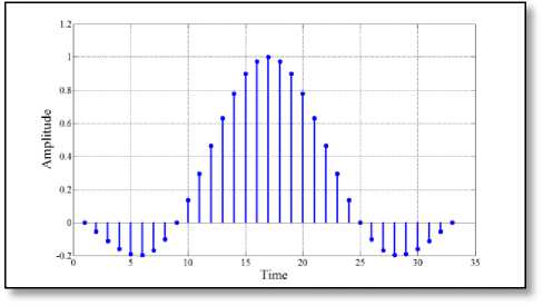
Fig. 4 ( a ) Standard RC pulse-shaping filter
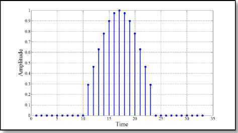
Fig. 4 ( b ) Chandra’s filter [11]
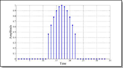
Fig. 4 ( c ) Proposed pulse-shaping filter
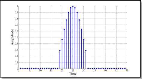
Fig. 5 ( c ) Proposed pulse-shaping filter
Fig. 5 Impulse response of different 49-length filter
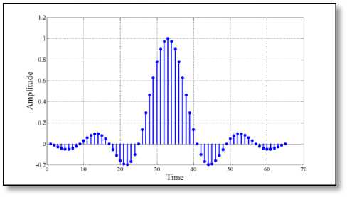
Fig. 4 Impulse response of different 33-length filter
-
Fig. 5 ( a ) Standard RC pulse-shaping filter
-
Fig. 6 ( a ) Standard RC pulse-shaping filter
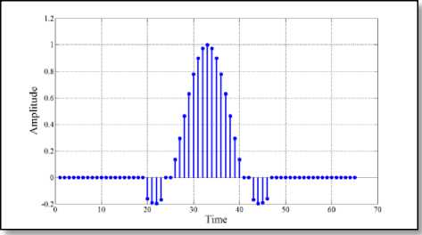
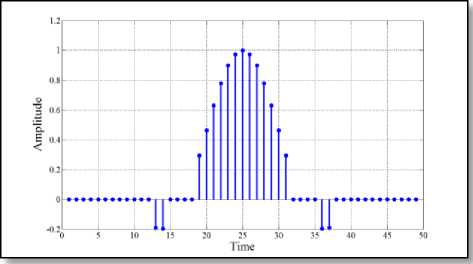
Fig. 6 ( b ) Chandra’s filter [11]
Fig. 5 ( b ) Chandra’s filter [11]
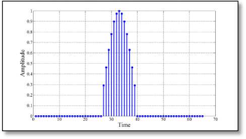
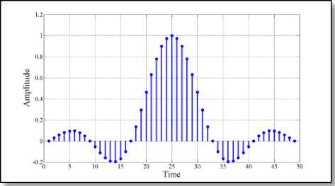
Fig. 6 ( c ) Proposed pulse-shaping filter
-
Fig. 6 Impulse response of different 65-length filter
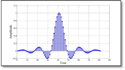
Fig. 7 ( a ) Standard RC pulse-shaping filter
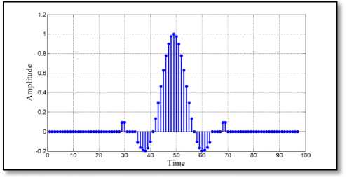
Fig. 8 ( b ) Chandra’s filter [11]
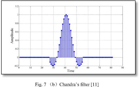
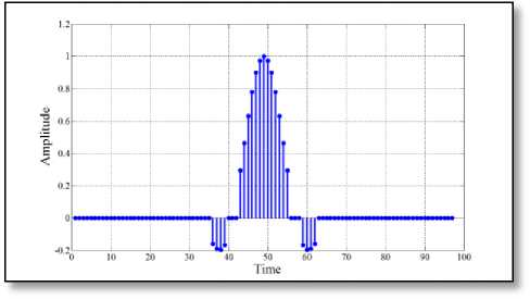
Fig. 8 ( c ) Proposed pulse-shaping filter
Fig. 8 Impulse response of different 97-length filter
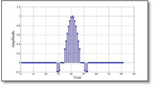
Fig. 7 ( c ) Proposed pulse-shaping filter
Fig. 7 Impulse response of different 81-length filter
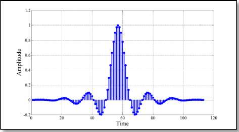
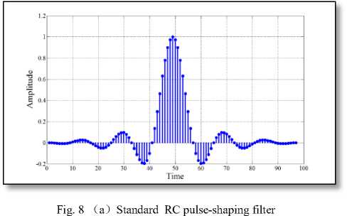
Fig. 9 ( a ) Standard RC pulse-shaping filter
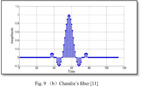
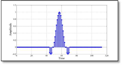
Fig. 9 ( c ) Proposed pulse-shaping filter
Fig. 9 Impulse response of different 113-length filter
impulse response for different lengths of the proposed filter. More specifically, the main lobe of the impulse response of the proposed filter has almost similar characteristics to that of standard RC filter. However, most of the side lobe amplitudes have been diminished to zero by the incorporation of the proposed algorithm. This has the effect of minimizing the transmitted power as thoroughly listed in TABLE 2 and consequently made our proposed filter more power efficient.
After analyzing the filter performance in time domain, the frequency domain characteristics of different filters has also been demonstrated by plotting the magnitude spectrum of the proposed pulse-shaping filter of seven different lengths as in Fig. 11 to Fig. 17 respectively.
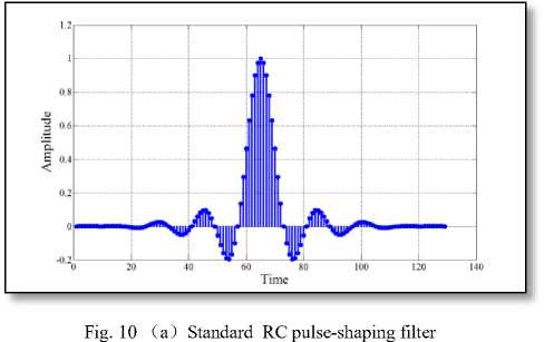
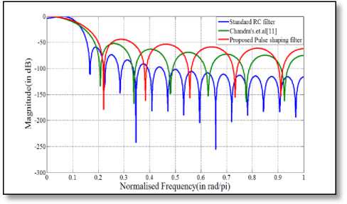
Fig.11 Comparison of magnitude response amongst 33-length filter
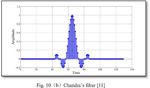
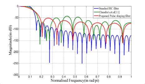
Fig.12 Comparison of magnitude response for filter length 49
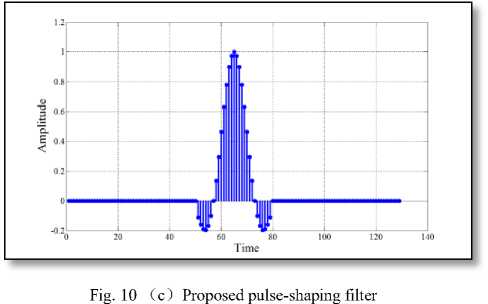
Fig. 10 Impulse response of different 129-length filter
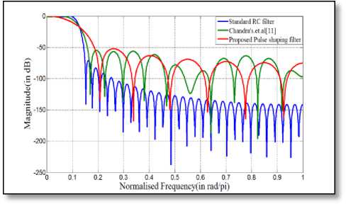
Fig.13 Comparison of magnitude response amongst 65-length filter
Looking at the above figures, an important observation can be made regarding the nature of the
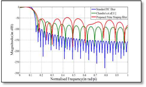
Fig.14 Comparison of magnitude response amongst 81-length filter
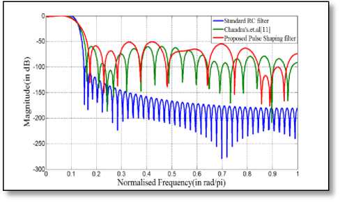
Fig.15 Comparison of magnitude response amongst 97-length filter
shaping filter is almost similar to that of the standard RC filter in the pass band region of interest. However, in the stop band region, the designed pulse-shaping filter exhibits less attenuation than the standard one but this amount of attenuation is comparable with that of Chandra’s filter [11]. Nevertheless, the designed FIR filter always produces an attenuation of 55 dB or more in the stop band region, which is as an acceptable amount of attenuation for practical use.
The coefficient values of the proposed filter, as obtained through MATLAB for different lengths of the filter, has been quantized into 8 bit word length and subsequently been implemented using XILINX ISE Design Suite 12.3 in order to get a detail idea about the requirement of hardware elements. These hardware elements are used for the design and implementation of power efficient finite impulse response filter on a Field Programmable Gate Array (FPGA) chip. The results thus obtained are then compared with that of the standard RC and Chandra’s filter [11] in TABLE 3 to TABLE 5 below to make our analysis more comprehensive.
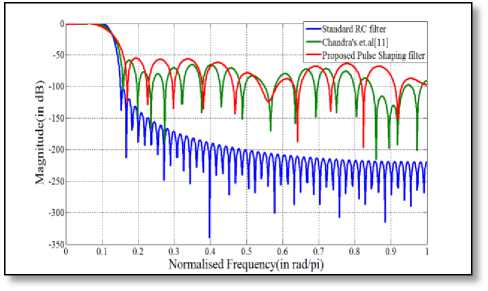
Fig.16 Comparison of magnitude response amongst 113-length filter
TABLE 3. COMPARISON OF DIFFERENT HARDWARE REQUIREMENT OF STANDARD RC, CHANDRA’S ET ALGORITHM [11] AND PROPOSED FILTER FOR LENGTH 33
|
Parameters |
Standard RC filter |
Chandra’s filter [11] |
Proposed pulse-shaping filter |
|
Input Buffer |
2 |
2 |
2 |
|
Output Buffer |
1 |
1 |
1 |
|
Delay |
39 |
28 |
27 |
|
Full Adder |
48 |
29 |
26 |
|
Subtractor |
1 |
1 |
1 |
|
Total Memory usage in KB |
187404 |
186508 |
186380 |
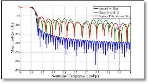
Fig.17 Comparison of magnitude response amongst 129-length filter
TABLE 4. COMPARISON OF DIFFERENT HARDWARE REQUIREMENT OF STANDARD RC, CHANDRA’S ET ALGORITHM [11] AND PROPOSED FILTER FOR LENGTH 49
|
Parameters |
Standard RC filter |
Chandra’s filter [11] |
Proposed pulse-shaping filter |
|
Input Buffer |
2 |
2 |
2 |
|
Output Buffer |
1 |
1 |
1 |
|
Delay |
39 |
39 |
37 |
|
Full Adder |
48 |
35 |
30 |
|
Subtractor |
1 |
1 |
1 |
|
Total Memory usage in KB |
187404 |
187276 |
187148 |
From the comparison of magnitude response for different lengths of the filter, it can be unambiguously inferred that the performance of the designed FIR pulse-
TABLE 5. COMPARISON OF DIFFERENT HARDWARE REQUIREMENT OF STANDARD RC, CHANDRA’S ET ALGORITHM [11] AND PROPOSED FILTER FOR LENGTH 65
|
Parameters |
Standard RC filter |
Chandra’s filter[11] |
Proposed pulse-shaping filter |
|
Input Buffer |
2 |
2 |
2 |
|
Output Buffer |
1 |
1 |
1 |
|
Delay |
39 |
39 |
39 |
|
Full Adder |
50 |
29 |
26 |
|
Subtractor |
1 |
1 |
1 |
|
Total Memory usage in KB |
187276 |
186572 |
186764 |
With regard to the number of delay elements and full-adder blocks on the FPGA chip, our proposed approach for pulse-shaping FIR filter design exhibits significant improvement over others, as inferred from Table 3 to Table 5. More specifically, requirement of delay has been reduced by 30.77% and 5% with 33 and 49-length proposed pulse-shaping filter in comparison to standard RC filter. On the other hand, in comparison to Chandra’s filter [11], the same improvement has been found to be as 3.57% and 5% respectively. As far as the requirement of full-adder is concerned, our approach is in need of 45.83%, 37.5% and 48% fewer hardware consumption with respect to standard RC filter and 10.34%, 14.28% and 10.34% less hardware usage with respect to the filter designed in [11] for a length of 33, 49 and 65 respectively. But, there has been no change in the number of input buffer, output buffer and subtractor requirement. Thus, our proposed technique demonstrates a remarkable contribution in the current field of power efficient FIR filter design by lowering the hardware cost significantly without allowing the achievable filter performance to go beyond its acceptable limit.
-
V. CONCLUSION
This paper presents in detail an algorithm to reduce the number of non-zero coefficients of standard pulseshaping FIR filter to enhance its speed of operation. An encouraging result has been obtained in terms of the impulse response and magnitude response of the proposed FIR filter of different lengths with the new sets of coefficients. The simulation results through the use of MATLAB 7.0 and XILINX ISE Design Suite 12.3 support the fact that the FIR filter designed with reduced number of filter coefficients also provides an acceptable performance in all respect. Since the proposed filter seems to be an alternative to the standard RC filter, the performance of the designed filter may be critically analyzed by using it as a pulse-shaping filter in any digital communication system.
References Design and Implementation of a Power Efficient Pulse-shaping Finite Impulse Response Filter on a Field Programmable Gate Array Chip
- Simon Haykin, “Communication Systems”, John Wiley and Sons, 4th Edition, 2001.
- K. Feher, “Wireless Digital Communications- Modulation and Spread Spectrum Applications”, Prentice Hall of India, pp. 119-125, 2005.
- John G. Proakis, “Digital Communications”, Tata McGraw Hill Book Co 3rd Edition, Chapter 9, 2001.
- Stanley A. White, “Applications of Distributed Arithmetic to Digital Signal Processing: A Tutorial Review”, IEEE ASSP Magazine, July, 1989.
- M.Rawski, P. Tomaszewicz, H. Selvaraj and T. Luba, “Efficient Implementation of Digital Filters with the use of Advanced Synthesis Methods Targeted FPGA Architectures”, in Proc. 8th Euromicro Conference on Digital System Design, IEEE, Computer Society, 2005.
- E. Lee, “Programmable DSP Architectures: Part II”, IEEE Transactions on Acoustics, Speech and Signal Processing Magazine, pp. 4-14, 1989.
- J. R. Choi, L.H. Jung, S.W. Jung and J. H. Choi “Structured Design of a 288 tap FIR Filter by optimized partial tree compression”, IEEE Solid State Circuits, vol. 32, pp. 468-476, March 1997.
- S. K. Mitra, “Digital Signal Processing: A Computer based Approach”, Tata McGraw Hill Co., 2001
- M. A. M Eshtawie and M. B. Othman, “An Algorithm Proposed for FIR Filter coefficients representation”, in Proc. International Journal of Applied Mathematics and Computer Sciences, vol. 4, pp. 24-30, 2008..
- C. J. Nicol, P. Larsson, K. Azadet and J.H. O’Neill, “ A Low Power 128 tap Digital Adaptive Equalizer for Broadcast Modem”, IEEE Solid State Circuits, vol. 32, pp. 1777-1789, Nov-1997.
- A. Chandra, S. Chattopadhyay and S.K.Sanyal, “An Efficient Algorithm to minimize the number of coefficients of FIR Pulse Shaping Filter”, in Proc. Annual IEEE India Conference (INDICON 2010), December 17-19, 2010, Kolkata
- S. Creaney and I. Kostarnov “Zero ISI on Raised Cosine Pulse Shaping”, Springer, 2011.
- Richard G. Lyons, “Understanding Digital Signal Processing”, Pearson Education Inc., 3rd Edition, 2011.
- Li Tan, “Digital Signal Processing: Fundamentals and Applications”, Academic Press, 1st Edition, 2008.
