Design and Simulation of Axial Flow Maglev Blood Pump

Author: Huachun Wu, Ziyan Wang, Xujun Lv
Journal: International Journal of Information Engineering and Electronic Business(IJIEEB) @ijieeb
Article in issue: 2 vol.3, 2011.
Free access
The axial flow maglev blood pump (AFMBP) has become a global research focus and emphasis for artificial ventricular assist device, which has no mechanical contact, mechanical friction, compact structure and light weight, can effectively solve thrombus and hemolysis. Magnetic suspension and impeller is two of the important parts in the axial flow maglev blood pump, and their structure largely determines the blood pump performance. The research adopts electromagnetic and fluid finite element analysis, and puts forward a method to design the magnetic suspension and impeller of axial flow blood pump, which tacks into account the small volume of axial blood pump. The magnetic bearing’s characteristics are evaluated by electromagnetic finite element analysis. The Blades have been designed by calculating aerofoil bone line, and make simulation analysis for different thicken ways of blade by Fluent software, and make a conclusion that the blade thickened with certain rules has better characteristics in the same conditions. The results will provide some guidance for design of axial flow maglev blood pump, and establish theoretical basis for application of the implantable artificial heart pump.
Magnetic Levitation, Blood Pump, Impeller, Axial Flow, Fluent, ANSYS
Short address: https://sciup.org/15013081
IDR: 15013081
Text of the scientific article Design and Simulation of Axial Flow Maglev Blood Pump
Published Online March 2011 in MECS
Heart failure is a mainly cause of level W heart death, According to the literature[1] reported that patients with heart failure is expected to reach 4.47 million in China, this is a serious threat to people's health. Through using heart transplantation, ventricular mechanical assistance, stem cell therapy, artificial organs substitution and alternative methods to treat it. Heart transplantation is a relatively mature technology, but there is a serious shortage of donated hearts. In this case, the development of artificial heart pump has become particularly important for treating the heart disease. The study of artificial heart pump in abroad is very early, and has made a great progress. The artificial heart pump has had some commercial product[2]. In contrast, the domestic research about artificial heart pump begins too later and exists some deficiencies on design and experiment.
In general, artificial heart pump is often divided into two types of pulsating and non-pulsating pump. Pulsating pump is suit for physiological characteristics, because of valve, stretchy membrane and larger ventricular volume, and with its bulk, non-implantation, and pulsating pump is often used in short-term treatment for patients awaiting heart transplantations in transitional term; the direction of current research is non-pulsating pump, because it has some advantages, such as small structure size, low power, little blood clots and long-term carry. To reduce complications, the development of artificial heart pump is shifting to rotating impeller pump which can produce constant blood stream, and small-sized or micro axial flow pump has become a research hotspot in this field in the world[3,4].
For the supporting type of axial flow blood pump, there are many choices, which are ball bearing, fluid film bearing and magnetic bearing. Because of existence of friction, they would cause thrombosis, destruction of blood cell and so on. At the same time, it also requires lubrication and sealing. Magnetic bearing offers some advantages of no mechanical contact, non-lubrication, low power and so on. In addition, axial flow blood pump impeller is motivated by motor to provide high-speed rotation, which causes blood flow force. Therefore, impeller is an important component in axial flow flood pump, and its structure largely determines the heart pump performance. In recent years, the domestic and foreign scholars investigate magnetic suspended and impeller of axial flow blood pump and have got some stage results. Literature [5] has proposed a structure of the axial flow blood pump, which its rotor is suspended by radial permanent magnetic bearing and single axial active magnetic bearing, but the radial stiffness and damping is not enough to resist the disturbance. In 2010, Allaire designed a different structure, consists of two radial magnetic bearings and one thrust permanent magnetic bearing[6]. According to the literature [7], the spiral blade profile was designed according to inlet, outlet velocity triangles and Euler work, and made solid modeling for impeller. Literature [8] mainly discussed the influence of impeller pitch angle for blood flow and the loss of convection. Literature [9] made a conclusion that the impeller with four blades had better performance through the simulation about the number of axial flow heart pump’s blades. According to the literature [10], the flow analysis were studied for axial heart pump impeller, and made the pressure distribution. However, magnetic suspended and impeller for axial flow maglev blood pump design still has some lacks of sufficient knowledge, and thus limits the effective application of maglev blood pump greatly. So it is necessary to analyze maglev blood pump impeller and supporting, fix main reasons of maglev blood pump performance, and offer some specific solutions to avoid the waste and blindness in design, manufacture and testing.
To solve the above problems, this paper does some research about magnetic supporting and impeller of axial flow maglev blood pump, give the magnetic suspended structure, discuss its magnetic distributing, and also design the blade by calculating bone line, and make some simulation analysis on different thicken ways of blade with Fluent software, and draw a conclusion that the blade thickened by certain rules has better performance in the same conditions. The conclusion provides some directions for axial flow maglev blood pump (AFMBP) design, and lays theoretical basis for implantable artificial heart pump application.
-
II. Magnetic Suspension Design of AFMBP
According to Earnshaw's Theorem, magnetic force and distance are inversely proportional to the square of system impossible to achieve a stable three-dimensional space suspension, meaning that all permanent magnetic levitation is impossible to achieve. So hybrid magnetic levitation will be adopted, which decrease structure, save power and so on.
-
A. Design of Axial Flow Maglev Blood Pump
In order to guarantee the rotor stability and have good dynamic characteristics, also need a certain stiffness and damping. A structure of axial flow maglev blood pump diagram is shown in Fig. 1.
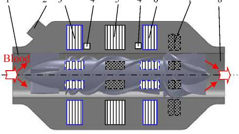
Figure 1. Diagrammatic illustration of the structure 1-Inlet 2-Line Outlet 3,6–Radial Magnetic Bearing 4-Hall Sensor 5-Motor 7-Axial Permanet Magnetic Bearing 8-Outlet
Fig. 1 shows the cross section of maglev blood pump structure equipping the proposed hybrid magnetic levitation. The maglev blood pump consists of an impeller, two radial active magnetic bearings (RAMB), one axial permanent magnetic bearing (APMB), four hall sensors and so on. The axial flow maglev blood pump, as shown in Fig. 1, has a total length 100mm, an outer diameter of 40mm and an impeller outer diameter of 18.5mm. It is designed to produce a flow rate of 6L/min at the pressure of 100mm/Hg when operating at a rotational speed of 7,000 rpm. Some characteristics of the hybrid magnetic levitation are given in Table I. The impeller is enclosed in the rotor that is driven by the brushless DC motor and supported by two RAMB and APMB without mechanical contact. The blood flow is in the axial direction with respect to the inlet and outlet cannula, which is, passing through the inducer, the impeller and the diffuser. The inducer and diffuser are enclosed in the rotor without contact, and the impeller is shrunk-fit into the bore of the rotor.
TABLE I.
P arameters of H ybrid M agnetic L evitation
|
Items |
Front RAMB |
Rear RAMB |
APMB |
|
Air Gap, mm |
1 |
1 |
1 |
|
Max Load, N |
5 |
5 |
5 |
|
Max Current, A |
1 |
1 |
/ |
|
Coil Turns |
50 |
50 |
/ |
For RAMB, the magnetic bearing core is made from 0.2mm thick silicon steel laminations which will help to decrease eddy current and hysteresis loss. Copper winding are wound around the core, and the generated flux loop. There is two kind permanent magnet rings in the rotor and stator which is made of NdFeB magnet material to produce the magnetic flux for the axial controlling. Two hall sensors are placed in the orthogonal directions on each side to measure radial positions of the rotor for controlling the rotor. The electromagnetic force on the rotor in one direction can be expressed by Equation (1).
= Д о A a N 2
( I 0 + i c У ( I 0 - i c У
( g о - x ) 2 ( g о + x ) 2 _
Where μ 0 , the permeability of free air: 4π×10-7 (T∙m/A), N is the coil number, A a is the cross section area of the flux, I 0 is the coil bias current, i c is control current, g 0 is the nominal air gap, x is the rotor displacement.
-
B. Analysis of Axial Permanent Magnetic Bearing
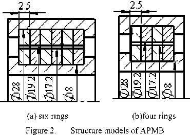
To achieve detailed size of axial permanent magnetic bearing, 2-D magnetic field analysis using ANSYS is carried out. Fig. 2 shows analytical model of axial permanent magnetic bearing, which are six rings and four rings respectively. Finally four rings are chose, according to the compact structure. The air gap between the rotor and stator is determined 1mm. The other parameters are determined through the analysis.
Generally there are three steps about magnetic field in ANSYS software.
Figure 1. Establishing FEA model which includes constructing geometry model, defining elements types, meshing and attributing materials.
Figure 2. Applying boundary conditions and load, solving equations.
Figure 3. Viewing the result.
For this model, there are three kinds of materials, namely air, non-ferrous and permanent magnet regions. For air region, specify a relative permeability of 1. For non-ferrous region, specify a relative permeability of 100. The permanent magnet is NdFeB, and its demagnetization curve is a straight line, so just sets the relative magnetic permeability and coercive force. The residual induction B r equal to 1.0T, coercive force H r is 895KA/m, so permeability as shows equation (2).
Ц =
B r
Ц Hr
1.0
4 п х 10 - 7 х 895000
= 0.889 ( 2 )
C. Analysis of Radial Active Magnetic Bearing
Where μ 0 is free space permeability, 4π×10-7H/m.
The calculated flux density distributions and flux lines are shown in Fig. 3 and Fig. 4.
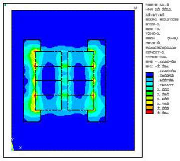
Figure 3. Flux density of APMB
Radial analysis is same as the axial permanent magnetic bearing. Therefore, flux density distributions and flux lines are provided, which are shown in Fig. 6 and Fig. 7.
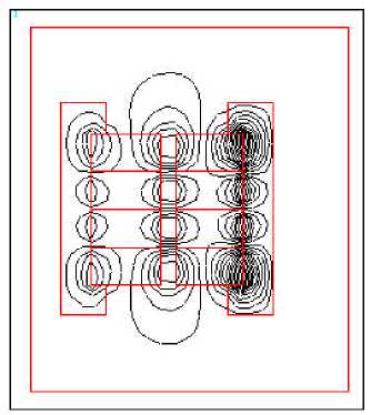
Figure 4. Flux lines of APMB
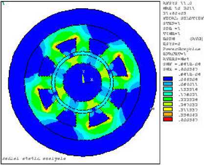
Figure 6. Flux density of RAMB
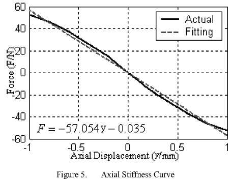
According to ANSYS calculation, the axial stiffness ( K y ) was calculated, which is shown in Fig. 5. The stiffness value is 57.054N/mm.
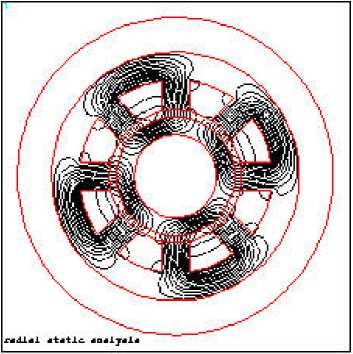
Figure 7. Flux lines of RAMB
III. The Impeller Design of AFMBP
The traditional design method of axial flow pump is to make sure the basic parameter first, such as pump lift, flow rate and pump suction head, which can be used to calculate the specific speed, hub ratio, number and thickness of blades of the pump. Then obtain blade dimensions by calculating blade grid at different cross section using lift force or arc method.
However, because axial flow heart pump is small, the traditional design method and experimental formula are not suitable for it. Here, the rotate speed, flow rate and differential pressure between import and export of the pump are assumed to be known, that is, the rotate speed of axial heart pump is 7,000 rpm, the inlet and outlet differential pressure is 100 mmHg, the flow rate is 6L/min.
-
A. Head Estimate
Use Bernoulli equation and blade velocity triangle to confirm the head H .
_ . Pi , «1v1 _ _ , P2 . «2v22 , . „ z 1 +---1--= z 2 +---1---+ AH
Y 2 g у 2 g
Where A H is the energy loss between effective sections. If the motor acts, H=- A H The pressure difference p 2- pb and altitude difference z 2- z 1 are known. The speed can be estimated by flow rate and velocity triangle. у is blood severe.
According to import and export velocity triangle of the blade, another condition can be confirmed. As showed in
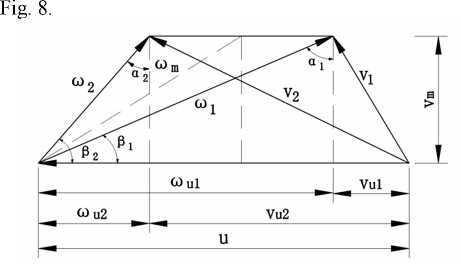
Figure 8. Import and export velocity triangle of the blade
According to Fig. 1, know Avu = vu2 - vu 1 , and u > Avu, so the second condition which is H < — can g be derived through corresponding formulas, and then have the upper limit of the head. According to the upper and lower limits of the head, and considering the hydraulic loss of the pump, the head H can be confirmed.
-
B. Other Basic Parameters
After determining head, according to the literature [11], we can obtain specific speed n s , select hub ratio dh / D , calculate the impeller diameter, hub diameter and the speed of impeller inlet. And select the appropriate number of blade and blade thickness[9]. get the inlet velocity according the formula v m = (0.06 ~ 0.08)3/ Qn2 , the value of the v m is the bigger the better.
-
C. Determine of the Chord Length l
Using following experimental formula to figure out cascade density[12]:
- = 6.28 ( K H ) - 0.03 ( 4 )
Where: t is the blade pitch, K H is the coefficient of the head.
This method overcomes the look-up table interpolation, KH can be obtained by specific speed ns and flow coefficient K Q . The length of chord l can be obtained by the density of the cascade multiplying the blade pitch.
-
D. Determine the Import and Export Vane Angle and Airfoil Placed Angle в ’
Import and export vane angle can be obtained from import and export velocity triangle which is shown in Fig. 1 The в 1 is the import vane angle, в 2 is the export vane angle.
Figure out airfoil placed angle from formula в ' = P m + 5 + 0.2( в 2 - Д ) . 6 is compensate incidence angle which is used to correct vane angle. According to Vane Pump Design Manual, 5 is not more than 8° when corrected airfoil. 0.2( P 2 - P 1 ) is the increased flow reserve angle for increasing the blade’s ability to different flow rate.
-
E. Determine and Thicken the Airfoil Bone Line
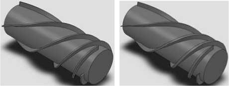
The chord length, airfoil placed angle and the curvature radius of the bone line are used to determine the airfoil bone line. The thickening of the airfoil is done by certain rules. Table II shows the dimensions of the impeller, and the solid model is shown in Fig. 9, established by Solidworks.
TABLE II.
I mpeller D imensions
|
Name |
Parameter |
|
Blades number |
4 |
|
Chord length |
72mm |
|
Import vane angle |
12° |
|
Export vane angle |
75° |
|
Airfoil placed angle |
38° |
|
Hub diameter |
14.8mm |
|
Outer diameter of blades |
18.5mm |
|
unilateral clearance between wall and outer edge |
0.3mm |
(a) Isopachous (b) Thickened
Figure 9. Blade model
IV. Fluent Simulation Analysis of Axial Flow Heart Pump
The traditional design of heart pump needs repeated experiments and corrections, the design cycle is long, and the cost is high. With the development of the computer technology, fluid mechanics and finite element theory, computational fluid dynamics (CFD) has been applied to the internal flow field and flow performance simulation of the heart pumps. It shortens the design cycle, improves efficiency and reliability. Fluent can be compatible with Solidworks software very well. Solidworks model can be directly imported to gambit which is the pretreatment module of Fluent software. And after proper Boolean operations, it can generate blood flow channel model, then the model can be analyzed after the meshing.
This paper will provide a contrast about two impeller models. Fig. 9(a) is scheme one, and shows the isopachous blade with the thickness of 0.5mm and fillets in both ends; Fig. 9(b) is scheme two, shows the variable thickness blade model, whose maximum thickness is 1mm and thickness variation is shown in Table III.
(a) Scheme I
(b) Scheme II
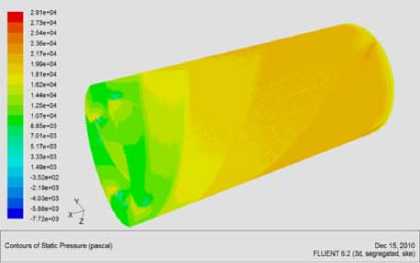
Figure 10. Static pressure contours
From the static pressure contours, in the same conditions, the pressure distribution of the impeller whose blade thickened according to certain rules is more reasonable than uniform thickness blade impeller, the inlet pressure is low, and gradually increases to the impeller exit. From the numerical point of view, the maximum and minimum pressure of scheme I are respectively -7716Pa and 29106Pa, scheme II are 5856Pa and 22948Pa, both of which can meet the requirement of 100mmHg, but scheme II meets the requirements better than scheme I.
TABLE III.
A rc A irfoil T hickness V ariation
|
x / l % |
0 |
10 |
20 |
30 |
40 |
50 |
60 |
70 |
80 |
90 |
100 |
|
y / y max % |
14.7 |
66.2 |
84.0 |
94.9 |
99.8 |
98.2 |
89.5 |
75.6 |
56.0 |
34.2 |
9.2 |
-
A. Meshing
Because the impeller flow channel calculation area is relatively complex, so use unstructured tetrahedral grids to obtain faster speed and higher meshing quality. Scheme one has 280900 grids, mesh quality no greater than 0.97 , it meets one of the most basic convergence conditions. Scheme two has 233344 grids; the max quality of the grids is 0.97.
-
B. Basic Parameters
Because blood is not pure Newtonian fluid, if use the non-Newtonian fluid to simulation, can make the simulation process to be very complicated. But in some cut strain, blood can be regarded as Newton fluid; many domestic and foreign scholars also treat it like this. Blood viscosity is commonly 3 ~ 4 (10-3) Pa ﹒ s , here take 0.0035 Pa ﹒ s. Normal adult heart blood flow rate is 6L/min, normal blood pressure is 80 ~ 120mmHg, take pressure differential for 100mmHg, about 13333.2Pa. Blood density is 1055kg/m3, rotation speed is 7000rpm. Regard mass-flow-inlet as import boundary condition, and the flow rate is 0.1055kg/s. Regard pressure-outlet as export boundary condition, and set export pressure as 110mmHg(14600Pa). Choose the steady-state calculation, using k - ε which is standard turbulence model, use solid wall without slipping as wall condition.
-
C. CFD Simulation Results Analysis
Both schemes converges around 160 steps, and the corresponding physical quantities no longer change. The static pressure distribution cloud chart is shown in Fig. 10.
(a) Scheme I
(b) Scheme II
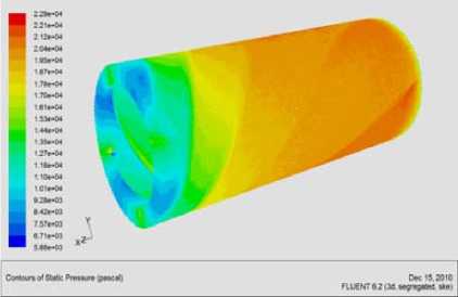
Figure 11. Pressure distribution at the entrance of the impeller
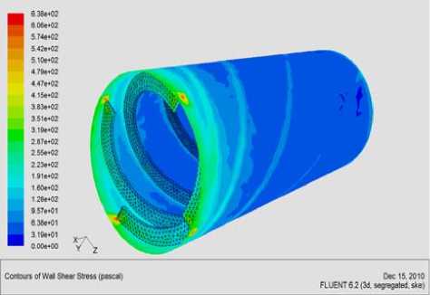
It can be seen from Fig. 11, in both schemes, the pressure of the front-end of the impeller’s blade is lager than other regions, but scheme I is much larger than scheme II. Too much pressure change is likely to cause large shear stress, and can destruct blood cells.
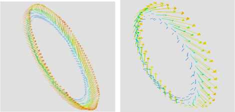
The maximum flow rate of the both two schemes is about 7m/s, and scheme II is slightly smaller. The speed of blood flow near the hub is low and near the outer edge of the blade is high. Fig. 12 shows the impeller outlet velocity vector, the speed of scheme II is slightly larger than scheme I.
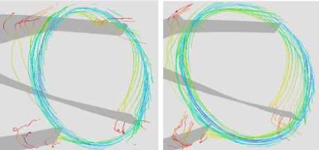
Fig. 13 shows the impeller exit flow line chart, it can be seen that both the two schemes have a small amount of backflow at the exit, which is not conducive to blood flow.
(a) Scheme I (b) Scheme II
Figure 12. Impeller outlet velocity vector
(a) Scheme I
(b) Scheme II
Figure 13. Impeller exit flow line
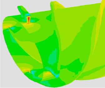
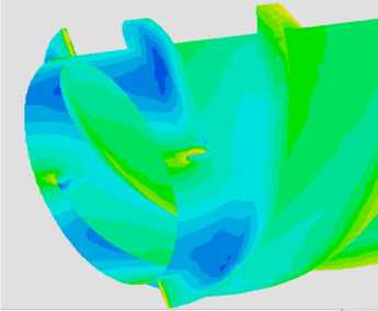
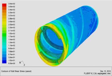
Fig. 14 shows the shear stress distribution diagram of the impeller. Maximum shear stress of the both two schemes is between the wall and the blades’ upper edge of front end, and the sizes are 638Pa and 384Pa respectively. But the blood suffers the shear stress smaller than 400Pa in 0.1s may think to be safe, so scheme II is more appropriate than scheme I.
(a) Scheme I
(b) Scheme II
Figure 14. Impeller shear stress diagram
V. Conclusions
This paper designed magnetic suspension and elaborated the design process of impeller for axial maglev heart pump, made the simulation analysis of structure with Ansys and Fluent software, and compared the uniform thickness blade impeller with the blade impeller which thickened according to certain rules, then obtained the following conclusions:
-
(1) The magnetic suspended structure was designed. The maglev blood pump consists of an impeller, two radial active magnetic bearings, one axial permanent magnetic bearing, four hall sensors and so on.
-
(2) The uniform thickness blade impeller was compared with the blade impeller which thickened according to certain rules. Both the two methods can guarantee the static pressure which is 100mmHg, but the variable thickness blade impeller meets the requirements better because the pressure distribution is better distributed, from entrance to export with progressive increase, and the most tremendous pressure appears in the back of leaf blade. Meanwhile, in scheme II, the maximum shear stress is much smaller than scheme I, and in the blood withstanding range.
-
(3) In both two methods, the export ends have a small amount of reflux, easy to form thrombus, and the structure of the export end needs to be improved. The speed of export has a large circumference component; a guide wheel is needed to be added to eliminate the circumferential velocity component.
-
(4) Both the pressure and shear stress on the front end of blades are relatively large, that should be reduced by changing the impeller hub structure.
-
(5) Overall, in the same conditions, the impeller that the blade thickened according to certain rules is better than the impeller with uniform thickness blade in the pressure distribution, the shear stress and the speed of flow lines, so the design and modification of the structure should first consider the variable thickness blade.
Acknowledgment
The authors wish to thank National Nature Science Foundation of China, WUT. This work was supported in part by a grant from National Nature Science Foundation of China (50675163) and self-determined and innovative research funds of WUT.
References Design and Simulation of Axial Flow Maglev Blood Pump
- China Medical Tribune. 2008,4,10.C5 Edition
- Qu Zheng. Mechanical Circulatory Support of Modern Treatment of Heart Failure [M].Beijing, Science and Technology Literature Publishing House.2008
- Portner P M, Oyer P E, Pennington D G, et al. Implantable Electrical Left Ventricular Assist System: Bridge to Transplantation and the Future [J]. Ann Thorac Surg, 1989,47:142~150
- Pennington D G, McBride L R, Kanter K R, et al. Bridging to Heart Transplantation with Circulatory Support Devices [J]. J Heart Transplant, 1989,8:116~123
- Yong Guan, Shuqin Liu, Hongwei Li, et al. Study on Magnetic Bearings System in Axial-Flow Blood Pump[C].//2010 International Conference on Mechanic Automation and Control Engineering, June 26-28, 2010, Wuhan, China, 2010:3903~3907
- Paul Allaire. Design and Analysis of Magnetic Suspension for New Artificial Heart [C].//The 12th International Symposium on Magnetic Bearings, August 22-25, 2010, Wuhan University of Technology Press, Wuhan, 2010:XII.
- Yun Zhong, Tan Jianping, Yang Jianping. Design of an Embedded Micro Spiral Blood Pump Impeller [J]. Mechanical Engineering&Automation, 2006,138(5):4~9
- Matthew D. SINNOTT, Paul W. CLEARY. Effect of Rotor Blade Angle and Clearance on Blood Flow [C]//The 7th International Conference on CFD in the Minerals and Process Industries, December 9-11, 2009, Melbourne, Australia, 2009:1~6
- Wang Yingpeng, Song Xinwei, Ying Chtmtong. Decision for the Blade Number of an Axial Blood Pump [J]. Beijing Biomedical Engineering, 2007,26(6):589~592
- W. K. Chan, Y. W. Wong, S. Y. KOH, et al. Performance Characterization and CFD Analysis of an Axial Blood Pump [J]. Journal of Mechanics in Medicine and Biology, 2005,5:151~163
- Shenyang Institute of Pumps, Vane pump design manual [M]. Beijing, Machinery Industry Press,1983
- A.T. Teroscerlansky, S.Razagievetes. Vane pump calculation and structure [M].beijing: mechanical industry press, 1981
