Design and testing of injectors manufactured using additive technologies for a low-thrust liquid rocket engine

Author: Zhuravlev V.Y., Manokhina E.S., Tolstopyatov M.I.
Journal: Siberian Aerospace Journal @vestnik-sibsau-en
Section: Aviation and spacecraft engineering
Article in issue: 1 vol.26, 2025.
Free access
Modern liquid rocket engines of low thrust (LRELT) represent complex engineering struc-tures, which are subject to very high requirements in terms of efficiency, reliability, and cost-effectiveness. To confirm the characteristics of the developed designs, a comprehensive set of tests for prototype samples is required, allowing their operability to be verified under conditions close to real-life operation. As part of this work, a thermodynamic calculation of the LRELT chamber for fuel components such as liquid kerosene and gaseous oxygen was conducted. The injector calculation method used in this work is based on the application of similarity criteria. This allows the transition from small-scale injectors to those suitable for full-scale testing, including stand tests using the “hydroflush” method. For testing, a specialized test rig was created, allowing the testing of injectors manufactured using modern additive technologies, such as 3D printing from polymer materials. This not only reduces the cost of creating prototypes but also accelerates the testing process. The injector tests on the stand play a crucial role in verifying their operability. This testing method allows studying the behavior of injectors in condi-tions as close to operational as possible. In this study, injectors manufactured using additive technologies from polymer plastic were used. The use of such materials in the early stages of testing helped to reduce costs and time resources for producing prototype samples. During the tests, the injectors were subjected to liquid at a specified pressure differential, which allowed their operability and fuel distribution uniformity to be assessed. The results of the tests demonstrated a high degree of correlation between theoretical calculations and actual data. The injectors showed stable operation corresponding to the calculated characteristics, and also proved their suitability for further development stages. The use of additive technologies in the manu-facturing of the injectors confirmed its effectiveness, allowing the prototype production cycle to be short-ened and costs reduced. Moreover, the “hydroflush” method proved to be a reliable means of verifying and validating the working characteristics of the injectors, which is an important step toward their implementa-tion in real-world operations. Thus, the proposed methodology, which includes the use of similarity criteria and additive technologies, significantly simplifies the process of development and testing, improves accuracy, and brings the results closer to real operating conditions. This is especially important for increasing the reliability and quality of final products used in rocket and space technology, contributing to a reduction in operational risks.
Mixing, mixing head, liquid rocket engine, low-thrust engine, testing
Short address: https://sciup.org/148330600
IDR: 148330600 | UDC: 621.454.2 | DOI: 10.31772/2712-8970-2025-26-1-83-93
Text of the scientific article Design and testing of injectors manufactured using additive technologies for a low-thrust liquid rocket engine
In recent years, there has been significant development in the production technologies of liquid rocket engines (LRE) [1–4], especially low-thrust ones, which are widely used in the aerospace industry. Improving these engines requires not only the development of new designs, but also the modernization of existing test rigs. The use of the stand for educational and demonstration classes will also improve the quality of training for students studying in this area. One of such stands is the test complex of the Re-shetnev Siberian State University of Science and Technology [5], designed for fire tests of rocket engines with components such as “gaseous oxygen” and “gaseous methane”. Despite the successful operation of this stand, there was a need to upgrade it for testing rocket engines operating on the components “liquid kerosene” and “gaseous methane”. The main reason for this is the need to provide better cooling of the engine chamber, which in the future will increase the engine operating time and provide higher resistance of the chamber to the effects of high temperatures of combustion products.
As part of the modernization of the test rig for fire tests of low-thrust liquid rocket engines ( LRELT ), designed to operate on liquid kerosene and gaseous methane, a series of thermodynamic calculations of the engine chamber were carried out. The purpose of these calculations was to determine the geometric parameters of the actual ratio of fuel components and their mass flow rate, as well as the temperatures of combustion products and specific impulse. The thermodynamic calculation was carried out using the methodology [6; 7], the initial data for performing the calculation and the main results obtained are presented in Table 1. The gas-dynamic contour and three-dimensional model of the engine chamber obtained during the calculation are shown in Figs. 1 and 2.
Table 1
Mixing head designed for 3D printing
|
Initial data |
|
|
Oxidant |
O 2 |
|
Fuel |
Т1 |
|
Chamber pressure |
1 МПа |
|
Nozzle exit pressure |
0.00084 МПа |
|
External pressure |
0.00001 МПа |
|
Thrust |
200 Н |
|
Calculation results |
|
|
Mass flow |
0.062 кг/с |
|
Fuel consumption |
0.02 кг/с |
|
Oxidizer consumption |
0.042 кг/с |
|
Temperature in the combustion chamber |
3256 К |
|
Temperature at the nozzle exit |
1026 К |
|
Specific impulse |
3480 м/с |
|
Oxidizer Excess Ratio in the Combustion Chamber Core |
0.909 |
|
Oxidizer excess coefficient for the wall layer |
0.07 |
|
Average oxidizer excess ratio |
0.6 |
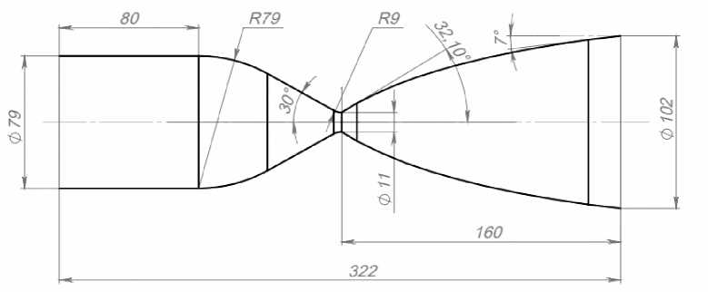
Рис. 1. Газодинамический контур камеры двигателя
Fig. 1. Gas-dynamic circuit of the engine chamber
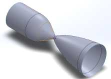
Рис. 2. 3D-модель камеры двигателя
Fig. 2. 3D model of the engine chamber
Statement of the problem
Designing a new mixing head for a liquid propellant rocket engine is a critical step, since the stability and efficiency of the engine operation depend on the efficiency of mixing the fuel components. The main task of the mixing head is to ensure uniform mixing of liquid kerosene and gaseous methane, which allows achieving complete and efficient combustion of the fuel. The most important and complex processes in the engine occur in the combustion chamber. Their nature is determined by the fuel and the mixing head. The prototype for the mixing head was the chamber of the LRELT propellant rocket engine, operating on the components “gaseous methane – gaseous oxygen” [1–4], which made it possible to reduce the task of designing the mixing head to the task of designing a fuel injector – liquid kerosene.
A single-component centrifugal injector with tangential component supply was selected as the fuel injector. The injector diagram with the main designations is shown in Fig. 3.
Рис. 3. Расчетная схема форсунки горючего
Fig. 3. Design diagram nozzle
When designing a single-component nozzle, different spray angles were taken into account 2α, pressure drops ∆P, geometric characteristics of the injector А:
А = R vh r ivh r vh
Injector flow rate coefficient μ:
Ц = ф
ф
2 — ф
Where φ is nozzle cross-section coefficient:
ф =1
^^^^м
r z2h r с2
3 Ae
+
3 Ae- - /A LT
2 2 8 27
Equivalent geometric characteristic of the injector, taking into account the influence of the viscosity of the real liquid,
А
А e Z
-
1 + 2 R vh ( R vh + d vh - r c ) ,
where λ is friction coefficient determined under the conditions at the inlet to the nozzle.
The friction coefficient under the conditions at the inlet to the injector λ is determined using an empirical relationship:
25,8
lg Z '12’58 2 -
( lg R vh )
Reynolds number at the nozzle inlet:
Re vh =
4 m f
ПП d vhJVh ’
where η is dynamic viscosity of the fuel component supplied through the injector , ṁ ф is mass flow rate of the component through the nozzle.
Parameters for performing calculations
As a result of calculations using the method [8–11], three variants of a nozzle for liquid kerosene were developed; the geometric dimensions are presented in Table 2.
Geometric dimensions of kerosene injectors
Table 2
|
Spray angle, deg |
90 |
100 |
110 |
|
Inner radius, r inn, mm |
0.56 |
0.6 |
0.7 |
|
Outer radius of the entrance, Rout, mm |
1.12 |
1.2 |
1.4 |
|
Inner radius of the entrance, R inn , mm |
0.35 |
0.29 |
0.27 |
|
Nozzle length l с, mm |
0.89 |
0.96 |
1.12 |
|
Nozzle height, h, mm |
1.12 |
1.2 |
1.4 |
|
Twist radius, R tw , mm |
1.47 |
1.49 |
1.67 |
In order to confirm the obtained calculation results, it was decided to conduct tests of the injector for hydraulic spillage on a special stand. Since the direct use of liquid kerosene is impossible due to the design of the stand, the study of the injector spray parameters is carried out on the working fluid -water.
For similarity of two or more hydrodynamic processes, the same coefficients must be identical (idem): Euler criterion – Eu and Reynolds criterion – Re in the nozzle cavities: and, where С is speed; υ is kinematic viscosity; L is nozzle diameter; ρ is density; р is pressure.
Thus, the hydrodynamic similarity of the injector cavities on water and liquid kerosene will be achieved by matching the coefficients. To evaluate the test results on the working fluid (water) and recalculated to the working fluid (liquid kerosene), the parameters of the liquids presented in Table 3 were used.
Based on the obtained values, a comparison of the similarity criteria of two liquids for injectors with different opening angles (90, 100, 110) was carried out. The results of calculating the similarity criteria of the injectors are presented in Table 4.
Liquid parameters
Table 3
|
Kerosene |
Water |
||
|
Kinematic viscosity ϑ, m2/s |
0,00000182 |
Kinematic viscosity ϑ, m2/s |
0,00000115 |
|
Density ρ, kg/m3 |
819 |
Density ρ, kg/m3 |
1000 |
|
Injector nozzle diameter |
Диаметр сопла форсунки |
||
|
L 90 , m |
0.00112 |
L 90 , m |
0.00107 |
|
L 100, m |
0.0012 |
L 100, m |
0.00117 |
|
L 110 , m |
0.0014 |
L 110 , m |
0.00131 |
|
Pressure |
Pressure |
||
|
P 90 , МPa |
1.25 |
P 90 , МPa |
1.25 |
|
P100, МPa |
1.4 |
P100, МPa |
1.4 |
|
P110, МPa |
1 |
P110, МPa |
1 |
Table 4
Results of calculations of similarity criteria of injectors
|
For Kerosene 90º „ 8.89 • 0.00112 Re = 0.00000182 = 5471 C = m_ =--- 0.0072— = 8.89 m / s P Fc 819 • 9.883-10 - 7 „ 1.25 •Ю6 Eu =-------- 7 = 19.3 819 • 8.892 |
For Water 90º o 8.05 • 0.00107 Re =----------= 5557 e 0.00000155 m & 0.0072 C =--- =--------------г = 8.05 m / s P Fc 1000 • 8.944 -10 - 7 „ 1.25 • 106 Eu =--------- 7 = 19.3 1000 • 8.052 |
|
For Kerosene 100º n 7.78 • 0.0012 Re =---------= 5129 e 0.00000182 m & 0.0072 C = — =----------z = 7.78 m / s P Fc 819 - 1.13-10 - 6 6 Eu = 1.4 10 = 28.2 819 • 7.782 |
For Water 100º D 6.73 • 0.00107 e 0.00000155 m & 0.0072 C = — =---------- = 6.73 m / s P Fc 1000 -1.07 -10 - 6 и 1.4 •Ю6 Eu =----------=- = 31 1000 • 6.732 |
|
For Kerosene 110º Re = 7.78 • 0.0 014 = 5984 e 0.00000182 m & 0.0072 C = — =---------- f = 5.7 m / s P Fc 819'1.54-10 - 6 г 1 ^ 10 6 n Eu == 31 819 • 5.7 2 |
For Water 110º 5. 3 • 0.00131 _11?(? 0.00000155 m & 0.0072 C =--- =--------------7- = 5.3 m / s P Fc 1000 • 1.35 -10 - 6 г 1 - 106 и Eu == 31 1000 • 5.32 |
The deviation of the Eu and Re coefficients does not exceed 5 %, therefore, the hydrodynamic processes in the cavities of the liquid kerosene nozzle and the water nozzle are similar. These results made it possible to obtain the geometric dimensions of the nozzle for testing with water spillage. The geometric dimensions of the nozzles for hydro-water spillage on the test bench are presented in Table 5, three-dimensional models of the nozzle for subsequent printing on a 3D printer are shown in Figs. 4 and 5.
Geometrical dimensions of nozzles for hydraulic flushing on the stand
Table 5
|
Spray angle, deg |
90 |
100 |
110 |
|
Inner radius, rinn, mm |
0.53 |
0.58 |
0.65 |
|
Outer radius of the entrance, Rout, mm |
1.07 |
1.17 |
1.15 |
|
Inner radius of the entrance, Rinn, mm |
0.33 |
0.28 |
0.24 |
|
Nozzle length lс, mm |
0.86 |
0.94 |
1.05 |
|
Nozzle height , h, mm |
1.07 |
1.17 |
1.15 |
|
Twist radius, Rtw, mm |
1.4 |
1.45 |
1.4 |
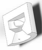
Рис. 4. 3D-модель форсунки в разрезе
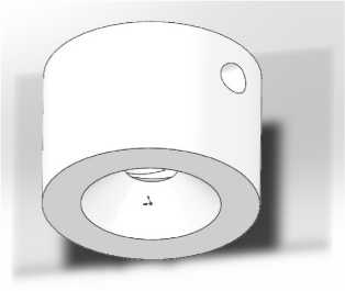
Рис. 5. 3D-модель форсунки
Fig. 4. 3D cross-sectional model of the nozzle
Fig. 5. 3D model of nozzle
Experimental study
The next stage of the work was printing nozzles with different geometric parameters and nozzle opening angles on a 3D printer for subsequent tests on a hydraulic flow stand. The purpose of this study was to analyze the change in flow direction depending on the geometry and spray angle to determine the best configuration of geometric dimensions and spray quality, as well as the uniformity of the nozzle torch. The setup diagram is shown in Fig. 6.
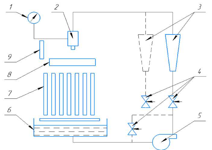
Рис. 6. Схема установки для испытания форсунок:
1 – манометр; 2 – форсунка; 3 – ротаметр; 4 – вентиль; 5 – насос; 6 – бак с водой;
7 – стеклянные трубки; 8 – насадки для снятия распыленной воды по радиусу или окружности;
9 – приспособление для измерения угла факела распыла
-
Fig. 6. Installation diagram for testing nozzles:
-
1 – pressure gauge; 2 – nozzle; 3 – rotameter; 4 – valve; 5 – pump; 6 – water tank;
7 – glass tubes; 8 – nozzles for removing sprayed water along a radius or circle;
9 – device for measuring the angle of the spray torch
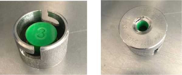
The working fluid in the installation is water. Water from tank 6 is fed by pump 5 through valve 4 and rotameter 3 to the inlet of nozzle 2 (Fig. 7 and 8). The required pressure drop on the nozzle is adjusted by valve 4 and measured by pressure gauge 1. Water flow is measured by rotameter 3 or by the volume of water drained in a known time. The spray angle is measured visually using special device 9 (Fig. 9). To remove the distribution of sprayed liquid along a circle or radius, nozzles 8 are used, from the sections of which water flows into glass tubes 7, where its level is measured. Water is poured into the tank from the water supply.
а б
Рис. 7. Установленная форсунка во втулку для пролива
-
Fig. 7. Installed nozzle in the bushing for spillage
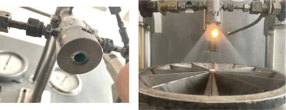
Рис. 9. Пролив форсунок
Рис. 8. Установленная втулка с форсункой на стенде
-
Fig. 8. Installed bushing with nozzle on a stand
Fig. 9. Nozzle testing
Research results
The spray pattern of a centrifugal injector is an important parameter that determines the efficiency of mixing the fuel with the oxidizer and, as a result, the quality of combustion in the chamber of a liquid rocket engine (LRE). Depending on the operating conditions and the design of the injector, the shape of the spray pattern can vary significantly, which affects the combustion process. The main types of spray patterns include a cone, tulip, and bubble, which are formed depending on the pressure drop and the action of various forces, such as inertial and surface tension forces of the liquid [12–15].
The results of flushing the three variants of injectors from Table 5 are presented in Tables 6–8. Each specimen was flushed 3 times at different pressure values from the specified range in order to determine the average value.
Table 6
Nozzle 1, average values
|
2α (spray angle ),in degrees |
40 |
50 |
50 |
|
m (mass flow ), g/s |
122.15 |
152.55 |
178.6 |
|
P (injector inlet pressure ), MPа |
0.0784 |
0.141 |
0.204 |
Table 7
Nozzle 2, average values
|
2α (spray angle ),in degrees |
57.5 |
60 |
70 |
|
m (mass flow ), g/s |
100.5 |
128.7 |
143.8 |
|
P (injector inlet pressure ), MPа |
0.0784 |
0.141 |
0.204 |
Table 8
Nozzle 3, average values
|
2α (spray angle ),in degrees |
67.5 |
75 |
80 |
|
m (mass flow ), g/s |
80.8 |
104.3 |
131 |
|
P (injector inlet pressure ), MPа |
0.0784 |
0.141 |
0.204 |
Conclusion
Based on the presented results, it can be concluded that nozzle 3 has the best performance (Table 8). The pouring process of this nozzle with fixation of the spray torch angle and the “cone” shape is shown in Fig. 9.
The presented methodology, which includes the use of similarity criteria, as well as additive technology methods, allows us to significantly simplify the development process and bring the testing process as close as possible to the actual operating conditions of the injectors.
