Design Modified Fuzzy Hybrid Technique: Tuning By GDO

Автор: Mohammad Shamsodini, Farzin Piltan, Mahdi Jafari, Omid reza Sadrnia, Omid Mahmoudi
Журнал: International Journal of Modern Education and Computer Science (IJMECS) @ijmecs
Статья в выпуске: 8 vol.5, 2013 года.
Бесплатный доступ
The Proportional Integral Derivative (PID) Fuzzy hybrid (switching mode computed torque sliding mode) Controller is presented in this research. The popularity of PID FHC controllers can be attributed to their robust performance in a wide range of operating conditions and partly to their functional simplicity. The process of setting of PID FHC controller can be determined as an optimization task. Over the years, use of intelligent strategies for tuning of these controllers has been growing. Biologically inspired evolutionary strategies have gained importance over other strategies because of their consistent performance over wide range of process models and their flexibility. This paper analyses the manual tuning techniques and compares the same with Gradient Descent tuning methods for tuning PID FHC controllers for flexible robot manipulator system and testing of the quality of process control in the simulation environment of MATLAB/SIMULINK Simulator.
PID fuzzy control, Sliding mode control, computed torque methodology, robust controller, Gradient descent optimization, flexible robot manipulator
Короткий адрес: https://sciup.org/15014577
IDR: 15014577
Текст научной статьи Design Modified Fuzzy Hybrid Technique: Tuning By GDO
Published Online October 2013 in MECS DOI: 10.5815/ijmecs.2013.08.07
Controller (control system) is a device which can sense information from linear or nonlinear system (e.g., robot arm) to improve the systems performance and the immune system behavior [11-20]. In feedback control system considering that there are many disturbances and also variable dynamic parameters something that is really necessary is keeping plant variables close to the desired value. Feedback control system development is the most important thing in many different fields of safety engineering. The main targets in design control systems are safety stability, good disturbance rejection to reach the best safety, and small tracking error[21-33]. At present, in some applications robot arms are used in unknown and unstructured environment, therefore strong mathematical tools used in new control methodologies to design nonlinear robust controller with an acceptable safety performance (e.g., minimum error, good trajectory, disturbance rejection). One of the most important nonlinear safety controllers is computed torque methodology which is used in nonlinear certain systems. This methodology is used in wide range areas such as in safety control access process; in aerospace applications and in IC engines because this methodology can solve some main challenging topics in safety control access such as resistivity to the external disturbance and stability. Even though, this methodology is used in wide range areas but, pure computed torque method has an important drawbacks beside uncertain system and also in presence of external disturbance. Uncertainty in system can causes some problems about safety in industrial factory. Sliding mode controller is an influential nonlinear controller to certain and uncertain systems which it is based on system’s dynamic model. Sliding mode controller is a powerful nonlinear robust controller under condition of partly uncertain dynamic parameters of system [34-69]. This controller is used to control of highly nonlinear systems especially for continuum robot. Chattering phenomenon and nonlinear equivalent dynamic formulation in uncertain dynamic parameter are two main drawbacks in pure sliding mode controller [20, 46-69]. The chattering phenomenon problem in pure sliding mode controller is reduced by using linear saturation boundary layer function but prove the stability is very difficult. Although the fuzzy-logic control is not a new technique, its application in this current research is considered to be novel since it aimed for an automated dynamic-less response rather than for the traditional objective of uncertainties compensation[38]. The intelligent tracking control using the fuzzy-logic technique provides a cost-and-time efficient control implementation due to the automated dynamic-less input. This in turn would further inspire multi-uncertainties testing for continuum robot [38]. Gradient descent is a first-order optimization algorithm. Gradient descent works in spaces of any number of dimensions, even in infinite-dimensional ones. In the latter case the search space is typically a function space, and one calculates the Gâteaux derivative of the functional to be minimized to determine the descent direction. The gradient descent can take much iteration to compute a local minimum with a required accuracy, if the curvature in different directions is very different for the given function. Gradient Descent Optimization (GDO) is one of the evolutionary optimization algorithms in the branch of non intelligence [1-10]. This algorithm was inspired by the social movement behavior of the birds in the flock searching for food. Compared to the other evolutionary algorithms, the main excellences of this algorithm are: Simple concept, easy to implement, robustness in tuning parameters, minimum storage space and both global and local exploration capabilities. These birds in a flock are symbolically described as particles. These particles are supposed to a swarm “flying” through the problem space. Each particle has a position and a velocity. Any particle’s position in the problem space has one solution for the problem. When a particle transfers from one place to another, a different problem solution is generated. Cost function evaluated the solution in order to provide the fitness value of a particle. “Best location” of each particle which has experienced up to now, is recorded in their memory, in order to determine the best fitness value.
Continuum robots represent a class of robots that have a biologically inspired form characterized by flexible backbones and high degrees-of-freedom structures [1-10]. Theoretically, the compliant nature of a continuum robot provides infinite degrees of freedom to these devices. However, there is a limitation set by the practical inability to incorporate infinite actuators in the device. Most of these robots are consequently underactuated (in terms of numbers of independent actuators) with respect to their anticipated tasks. In other words they must achieve a wide range of configurations with relatively few control inputs. This is partly due to the desire to keep the body structures (which, unlike in conventional rigid-link manipulators or fingers, are required to directly contact the environment) “clean and soft”, but also to exploit the extra control authority available due to the continuum contact conditions with a minimum number of actuators. For example, the Octarm VI continuum manipulator, discussed frequently in this paper, has nine independent actuated degrees-of-freedom with only three sections. Continuum manipulators differ fundamentally from rigid-link and hyper-redundant robots by having an unconventional structure that lacks links and joints. Hence, standard techniques like the Denavit-Hartenberg (D-H) algorithm cannot be directly applied for developing continuum arm kinematics. Moreover, the design of each continuum arm varies with respect to the flexible backbone present in the system, the positioning, type and number of actuators. The constraints imposed by these factors make the set of reachable configurations and nature of movements unique to every continuum robot. This makes it difficult to formulate generalized kinematic or dynamic models for continuum robot hardware. Thus, the kinematics (i.e. geometry based modeling) of a quite general set of prototypes of continuum manipulators has been developed and basic control strategies now exist based on these. The development of analytical models to analyze continuum arm dynamics (i.e. physics based models involving forces in addition to geometry) is an active, ongoing research topic in this field. From a practical perspective, the modeling approaches currently available in the literature prove to be very complicated and a dynamic model which could be conveniently implemented in an actual device’s real-time controller has not been developed yet. The absence of a computationally tractable dynamic model for these robots also prevents the study of interaction of external forces and the impact of collisions on these continuum structures. This impedes the study and ultimate usage of continuum robots in various practical applications like grasping and manipulation, where impulsive dynamics [1-4] are important factors. Although continuum robotics is an interesting subclass of robotics with promising applications for the future, from the current state of the literature, this field is still in its stages of inception.
This method is based on design partly sliding computed torque controller based on sliding surface slope discontinuous part and resolve the uncertainty term by fuzzy logic methodology. To tune the sliding surface slope and fuzzy logic gain updating factor as well as improve the output performance the iteration algorithm based on Gradient Descent Optimal Algorithm (GDOA) is introduced. The sliding surface gain (Я) and gain updating factor of this controller is adjusted off line depending on the iterations.
This paper is organized as follows; section 2, is served as an introduction to the sliding mode controller formulation algorithm and its application to control of continuum robot, dynamic of continuum robot and proof of stability, computed torque controller and fuzzy inference system. Part 3, introduces and describes the methodology algorithm. Section 4 presents the simulation results and discussion of this algorithm applied to a continuum robot and the final section describe the conclusion.
-
II. THEORY
-
A. Dynamic Formulation of Continuum Robot
The Continuum section analytical model developed here consists of three modules stacked together in series. In general, the model will be a more precise replication of the behavior of a continuum arm with a greater of modules included in series. However, we will show that three modules effectively represent the dynamic behavior of the hardware, so more complex models are not motivated. Thus, the constant curvature bend exhibited by the section is incorporated inherently within the model. The model resulting from the application of Lagrange’s equations of motion obtained for this system can be represented in the form
Fcoeff I = ^(у)» + C^^i + б(я) (1)
where т is a vector of input forces and q is a vector of generalized co-ordinates. The force coefficient matrix Fcoeff transforms the input forces to the generalized forces and torques in the system. The inertia matrix, D is composed of four block matrices. The block matrices that correspond to pure linear accelerations and pure angular accelerations in the system (on the top left and on the bottom right) are symmetric. The matrix C contains coefficients of the first order derivatives of the generalized co-ordinates. Since the system is nonlinear, many elements of C contain first order derivatives of the generalized co-ordinates. The remaining terms in the dynamic equations resulting from gravitational potential energies and spring energies are collected in the matrix G. The coefficient matrices of the dynamic equations are given below,
[xd, xd,xd,., xd( " 1)]r, and trucking error vector is defined by [6]:
x = x - xd = [x, ..., x( " 1)]r
Fcoeff = (2)
|
1 |
1 |
cos ( 0t ) |
cos ( 01 ) |
cos ( 01 + 0 2 ) |
cos ( 01 + 02 ) |
|
o |
o |
1 |
1 |
cos ( 02 ) |
cos ( 02 ) |
|
o |
o |
o |
o |
1 |
1 |
|
1 / 2 |
-1 / 2 |
1 / 2 |
-1 / 2 |
1 / 2 + s2si" ( 0 2 ) |
-1 / 2 + s2si" ( 02 ) |
|
o |
o |
1 / 2 |
-1 / 2 |
1 / 2 |
-1 / 2 |
|
o |
o |
o |
o |
1 / 2 |
-1 / 2 |
|
d(,) = |
(3) |
||||
|
m1 + m2 + m3 |
m2 cos(01) +m3 cos(01) |
m3cos(01 + 02) |
-m2s2si"(01) — mз5z5i"(01) — m3535i"(01 + 02) |
-m3535i"(01 + 02) o |
|
|
mzcos(91) +m3cos(01) |
m2 + m3 |
m3cos(02) |
-m3 s3si"(02) |
-m3S3Si"(02) o |
|
|
m3cos(01 + 93) |
m3 cos(02) |
m3 |
m3s3si"(02) |
o o |
|
|
— mz5z5i"(01) — m3535i"(01) -m353si"(01 + 03) |
-m3s3si"(02) |
mз5z5i"(0z) |
mzs2 + J, + J; + /3 + m3s2 + m3s2 + 2m3s3 cos(02)s2 |
J3 + т3$3 + J3 j + m 3 5 3 cos ( 0 2) s 2 1 |
|
|
-m353si"(01 + 02) |
- m3s 3si"( 02) |
o |
J3 + m,s + J, +m353cos(02)s2/ |
J2 + m3s3 + J3 J3 |
|
|
o |
o |
o |
Ji |
J! |
|
c( |
Q |
)= |
(4) |
||||
|
c„+ |
c21 |
-2m2si"(01)01 -2m35i"(01)01 |
-2m35i"(01 + 02) (01+ 02) |
-m2S2 cos(01)(01) +(1/2)(cu + c21) -m3S2 cos(01)(01) -m353 cos(01 + 02)(0г) |
-m3535i"(01 + 02) |
o |
|
|
o |
c12 + c22 |
-2m35i"(02) (01+ 02) |
-m3S3(01) + (1/2) (c12 + c22) -m3S2(01) -m353 co5(02)(01.) |
-2m353 cos(02)(01) -m3s3 CO5(0z)(0z) |
o |
||
|
o |
2m35i"(02)(01) |
c13 + c23 |
-m3s352 cos(02)(01.) -m3s3(01) |
-2m353(01) — mз5з(0z) |
(1/2) (c13 + c23) |
||
|
(1/2) (cn + c21) |
2m353cos(02)(01) -2m352(01) + 2m2s2(01) |
2m353(01 + 02) -2m352co5(02) (01+ 02) |
2m3535z si"(0z)(0z) +(17») (c11 + CZ1) |
m3S3S2 5i"(0z)(0z) |
o |
||
|
o |
(1/2)(c12 + c22) + 2m353cos(02)(01) |
2m3s3 (01 + 02) |
m3S3S2 sin(0z)(01) |
(12/») (c12 + czz') |
o |
||
|
o |
o |
(1/2)(c13 - c23) |
o |
o |
(12/») (c13 + c23) |
||
6(g) = (5)
-тгд - m2g + kn(S 1 + (1/2)0 ! - s01) + k 21 (S 1 - (1/2)0 ! - sOi) - m3g
-m2gcos(d1) + k 12 (s 2 + (1/2)0 2 - S o2 ) + k 22 (s 2 - (1/2)0 2 - S o2 ) - m 3 gcos(0 1 )
-m 3 gcos(0 1 + 02) + k 13(53 + (1/2)0 3 - S o3 ) + k2 3 (S 3 - (1/2)0 3 - S o3 )
m2s2gsin(0 1 ) + m 3 S 3 gsi"(0 1 + 02) + m 3 S 2 gsi"(0 1 ) + kn(S 1 +(1/2)0 1 -S o1 )(1/2) I
+k2 1 (S 1 - (1/2)0 1 -S o1 )(-1/2)
m 3 S 3 gsi"(0 1 + 02) + k 1 2(s2 + (1/2)0 2 - S o2 )(1/2) + k22(s2 - (1/2)0 2 - s o2 )(-1/2)
k 13 (s 3 +(1/2)0 3 -S o3 )(1/2) + k2 3 (s 3 - (1/2)0 3 - S o3 )(-1/2)
A time-varying sliding surface s(x, t) in the state space R " is given by [6]:
d
s(x, t) = (— + Я)"-1 x = o where λ is the positive constant. To further penalize tracking error, integral part can be used in sliding surface part as follows [6]:
s(x, t) = (^ + Я) " 1 ^J x dt) = o
The main target in this methodology is kept the sliding surface slope s(x, t) near to the zero. Therefore, one of the common strategies is to find input U outside of s(x, t) [6].
1 d ,(10)
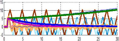
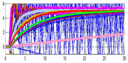
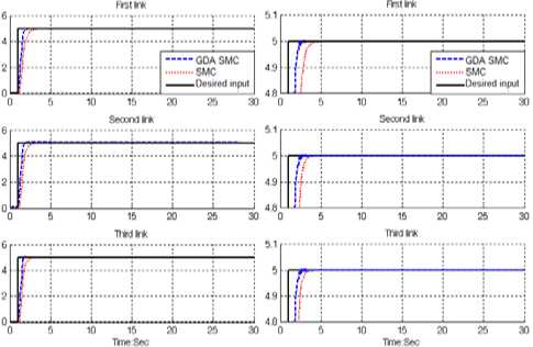
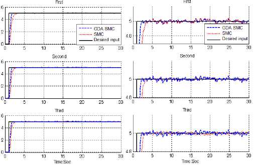
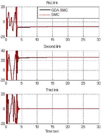
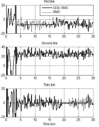
2dtS2(x, t) <- If S(0)>0^S(t) <-< To eliminate the derivative term, it is used an integral term from t=0 to t=treach Гt=treach d / rt—^each „ Jt=o dt5(t)<--Uo 4^ S(treach) - S(o)< -breach - o) Where treac^ is the time that trajectories reach to the sliding surface so, suppose S(treac^ = 0) defined as; ° - S(o)< -4(treac w> h) ^ t-reach < ^ And if S(o) < 0 ^ 0 - 5(o) < -breach) ^ (14) S(o) < -<(treach) ^ treach < ^ B. Sliding Mode Controller Consider a nonlinear single input dynamic system is defined by [6]: x^) = f (x) + 6(x)u Equation (14) guarantees time to reach the sliding surface is smaller than j^^o)! since the trajectories are outside of 5(t). Where u is the vector of control input, x(") is the "th derivation of x , x = [x, x, x,..., x(n-1)]r is the state vector, f (x) is unknown or uncertainty, and 6(x) is of known sign function. The main goal to design this controller is train to the desired state; xd = if streach = 5(o) ^ error(x - xd) = o (15) suppose S is defined as s(x, t) = ф + Я) X = (x-xd)+ X(x - Xd) The derivation of S, namely, 5 can be calculated as the following; S = (X - Xd) + X(X - Xd) suppose the second order system is defined as; X = f + u ^ S = f + U — Xd + A(X - Xd) Where f is the dynamic uncertain, and also since 5 = 0 and 5 = 0, to have the best approximation ,U is defined as U = -f + Xd - Я^ - Xd) A simple solution to get the sliding condition when the dynamic parameters have uncertainty is the switching control law [52-53]: Udis = U - K(X, t) • sgn(s) where the switching function sgn(S) is defined as [1, 6] ( 1 s > 0 sgn(s) = |-1s <0 (0s = 0 and the K(X, t) is the positive constant. Suppose by (22) the following equation can be written as, 1 d.., . r т(22) ^dts2(X, t) = S-S = [f - f - Ksgn(s)] • 5 = (f-f)-5-K|5| and if the equation (17) instead of (18) the sliding surface can be calculated as s(X, t) = ф + Я)2 (£ x dt) = (X - Xd) + 2Я(X - Xd) -A2(x - Xd) in this method the approximation of U is computed as [6] U = -f + Xy - 22(X - Xd) + A2(X-Xd) Based on above discussion, the sliding mode control law for multi degrees of freedom robot manipulator is written as [1, 6]: T = Teq + Tdis Where, the model-based component Teq is the nominal dynamics of systems calculated as follows [1]: Teq = [D-1 (f + C + 6) + S]D and Tdis is computed as [1]; Tdis = K • sgn(S) By (26) and (27) the sliding mode control of robot manipulator is calculated as; t = [D-1(f + C + 6)+ S]D + K • sgn(5) where 5 = Ле + e in PD-SMC and 5 = Ле + e + Ф2Ze inPID-SMC. C. Computed torque methodology: Computed torque controller (CTC) is a powerful nonlinear controller which it widely used in control of nonlinear systems. It is based on feedback linearization and computes the required arm torques using the nonlinear feedback control law. This controller works very well when all dynamic and physical parameters are known but when the robot has variation in dynamic parameters, in this situation the controller has no acceptable trajectory performance[14]. In practice, most of physical systems (e.g., continuum robot) parameters are unknown or time variant, therefore, computed torque like controller used to compensate dynamic equation of continuum robot [13-23]. When all dynamic and physical parameters are known, computed torque controller works fantastically; practically a large amount of systems have uncertainties, therefore computed torque like controller is the best case to solve this challenge. The central idea of computed torque controller (CTC) is feedback linearization so, originally this algorithm is called feedback linearization controller. It has assumed that the desired motion trajectory for the manipulator qd(t), as determined, by a path planner. Defines the tracking error as: e(t) = qd(t) - q„(t) (29) Where e(t) is error of the plant, qd(t) is desired input variable, that in our system is desired displacement, qa(t) is actual displacement. If an alternative linear statespace equation in the form X = .Ax + BU can be defined as X = [0 0]x + [0]U ,30) With U = -D-1(q). N(q, q) + D-1(q). t and this is known as the Brunousky canonical form. By equation (29) and (30) the Brunousky canonical form can be written in terms of the state X = [ег er]r as [24]: s[!3=[0 0]-[3+[0]u (31) With и = qd + D ^qMVfa. q) -t} (32) Then compute the required arm torques using inverse of equation (32), is; t = D(q)(qd - U) + V(q, q) (33) This is a nonlinear feedback control law that guarantees tracking of desired trajectory. Selecting proportional-plus-derivative (PD) feedback for U(t) results in the PD-computed torque controller [24]; t = D(q)(qd + K„e + Kpe) + V(q, q) (34) and the resulting linear error dynamics are (qd + Kpe + K„e) = о (35) According to the linear system theory, convergence of the tracking error to zero is guaranteed [24]. Where Kp and Kv are the controller gains. D. Proof of Stability The lyapunov formulation can be written as follows, V = 2st. D. S the derivation of V can be determined as, V = 1st. D. S + ST DS the dynamic equation of robot manipulator can be written based on the sliding surface as DS = -vs + DS + f + C + G(38) it is assumed that ST(D —2f + C + G)S = 0 by substituting (37) in (38) V = ^STDS-STf + CS + ST(DS + f + CS + G) = ST(DS + f + CS + G) suppose the control input is written as follows U = Uv+near + + = [^(f + C + G) + S]D + K. sgn(S) + f + CS + G by replacing the equation (41) in (40) V = ST(DS + f + C + G-DS-f+CS + G-(42) Ksgn(S) = ST (DS + f+CS + G- Ksgn(S)^ and |DS + f + CS + G| < |DS| + |f + CS + G| the Lemma equation in robot arm system can be written as follows Ku = [|DS| + |f + CS + G| + s]., i = 1,2,3, 4, ™ and finally; V<-^\i |Sil i=1 E. Fuzzy Logic Methodology Based on foundation of fuzzy logic methodology; fuzzy logic controller has played important rule to design nonlinear controller for nonlinear and uncertain systems [53]. However the application area for fuzzy control is really wide, the basic form for all command types of controllers consists of; Input fuzzification (binary-to-fuzzy [B/F] conversion) Fuzzy rule base (knowledge base), Inference engine and Output defuzzification (fuzzy-to-binary [F/B] conversion). Figure 1 shows the fuzzy controller part. The fuzzy inference engine offers a mechanism for transferring the rule base in fuzzy set which it is divided into two most important methods, namely, Mamdani method and Sugeno method. Mamdani method is one of the common fuzzy inference systems and he designed one of the first fuzzy controllers to control of system engine. Mamdani’s fuzzy inference system is divided into four major steps: fuzzification, rule evaluation, aggregation of the rule outputs and defuzzification. Michio Sugeno use a singleton as a membership function of the rule consequent part. The following definition shows the Mamdani and Sugeno fuzzy rule base [22-33] if x is A and "y is В then z is C 'mamdani (46) if x is A and yis В thenzis f(x, y)'sugeno' When x and у have crisp values fuzzification calculates the membership degrees for antecedent part. Rule evaluation focuses on fuzzy operation (AND/OR ) in the antecedent of the fuzzy rules. The aggregation is used to calculate the output fuzzy set and several methodologies can be used in fuzzy logic controller aggregation, namely, Max-Min aggregation, Sum-Min aggregation, Max-bounded product, Max-drastic product, Max-bounded sum, Max-algebraic sum and Min-max. Defuzzification is the last step in the fuzzy inference system which it is used to transform fuzzy set to crisp set. Consequently defuzzification’s input is the aggregate output and the defuzzification’s output is a crisp number. Centre of gravity method (COG) and Centre of area method (СОЛ) are two most common defuzzification methods. F. Gradient Descent Algorithm Gradient Descent Optimization (GDO) is one of the evolutionary optimization algorithms in the branch of non intelligence [4]. This algorithm was inspired by the social movement behavior of the birds in the flock searching for food. Compared to the other evolutionary algorithms, the main excellences of this algorithm are: Simple concept, easy to implement, robustness in tuning parameters, minimum storage space and both global and local exploration capabilities. These birds in a flock are symbolically described as particles. These particles are supposed to a swarm “flying” through the problem space. Each particle has a position and a velocity. Any particle’s position in the problem space has one solution for the problem. When a particle transfers from one place to another, a different problem solution is generated. Cost function evaluated the solution in order to provide the fitness value of a particle. “Best location” of each particle which has experienced up to now, is recorded in their memory, in order to determine the best fitness value. Particles of a gradient descent transmit the best location with each other to adapt their own location according to this best location to find the global minimum point. For every generation, the new location is computed by adding the particle’s current velocity to its location. GDO is initialized with a random population of solutions in N-dimensional problem space, the i th particle changes and updates its position and velocity according to the following formula: Vld = w x (Vld + Ci x rand! * (Pw - (47) Xld) + C2 x rand2 x (Pgd - Xld)) Where Xld is calculated by Xid = Xld + Vld (48) Where Vld is the inertia weight implies the speed of the particle moving along the dimensions in a problem space. Cx and C2 are acceleration parameters, called the cognitive and social parameters; randx and rand2 are functions that create random values in the range of (0, 1). Xld is the particle’s current location; Pld (personal best) is the location of the particle experienced its personal best fitness value; Pgd (global best) is the location of the particle experienced the highest best fitness value in entire population; d is the number of dimensions of the problem space; . W is the momentum part of the particle or constriction coefficient [5] and it is calculated based on the following equation; W = 2/ (2 - ф - Тф2—*^) (49) Ф=СХ+ C2 , ф >4 (50) Equation 10 needs each particle to record its location Xld, its velocity Vld, its personal best fitness value P id, and the whole population’s best fitness value Pgd. On the basis of following equation the best fitness value Xi is updated at each generation, where the sign / (.) represents the cost function; Xl (.) indicated the best fitness values; and t denotes the generation step. Xi (t + 1) = (51) ( Xl(t) f(Pd(t + 1))< Xl(t) If(Pd(t + 1)) f(Pd(t + 1)) > Xl(t) In GDO, the knowledge of each particle will not be substituted until the particle meets a new position vector with a higher competence value than the currently recorded value in its memory [6]. External disturbances influence on tracking trajectory, error rate and torque which result in chattering. But the values are not such a great values and these oscillations are in all physical systems. So, the sliding mode controller can reject perturbations and external disturbances if these parameters adjust properly. So the methodology which is applied in this paper in order to select the best values for these deterministic coefficients to accomplish high performance control is the Gradient Descent Optimization algorithm. This algorithm tunes the gains and determines the appropriate values for these parameters in harmony with the system which was introduced in rear part. III. Methodology Conversely pure sliding mode controller is a high-quality nonlinear controller; it has two important problems; chattering phenomenon and nonlinear equivalent dynamic formulation in uncertain dynamic parameter. Switching sliding mode methodology is a nonlinear robust and stable controller and computed torque controller is a nonlinear controller but it has a challenge in stability and robustness especially in presence of uncertainty and disturbance. Based on literature CTC formulation is written by; т = D(q) (qd + Kve + Kpe) + N(q, q) The sliding surface formulation and the rate of sliding surface formulation are calculated by; s(x, t) = (dt + A) x = (x - j:d) + A(x - xd) S = (it - itd) + A(x - Xd) To improve the stability based on LYAPUNOV formulation sliding surface formulation and derivative of it applied to CTC based on following formulation; т = D(q)x sgm(qd + KP((X —Xd) + (55) A(x — xd)) +Kp((x — xd) +Mx — Xd) )) + N(q, q) To resolve uncertain problem this research is focused on to design SISO sliding mode switching computed torque like methodology. The firs type of fuzzy systems is given by el£l (x) = eT£(x) m fto = y 1=1 Where 9 = (91.....9м)T, £(x) = (£1(x), ..., £M (x))T, and. £l (x) = и. i (xi) : n=i —4---Е?=1(ПП=1 HAi (Xi)). 91, ..., 9м are adjustable i parameters in (56). gA1(x1),...,gAm (xn) are given membership functions whose parameters will not change over time. Where 91,..., 9n are adjusted by an adaptation law. The general SISO if-then rules are given by Rl: if x1is A1 , x2 is Al2 , ..., xn is Aln (61) , then yiis Bli, ...,ym is Blm Where l = 1,2, .,M are fuzzy if-then rules; x = (x1, ., xn )T and у = (у1,., yn )T are the input and output vectors of the fuzzy system. The SISO fuzzy system is define as f (x) = ©T £(x) (62) Where Г A1 ti2 дМ -i 91, 91 , ... , 91 0X,9X.....9M й1 fl2 nM L9m, 9m , . , 9m3 S(x) = (£1(X),., SM (X))T, S1(x) = nn=1 pAl (Xi)/ !?=1(ПП=1 ИА1 (x4)) , and иА1 (x4) is defined in (58). To reduce the number of fuzzy rules, we divide the fuzzy system in to three parts: The second type of fuzzy systems is given by f(x) ZM=1“l П"=1бхр F1 (q, q) = ©1T£ (q, q) (64) = [“1T£ (q, q) ,., 9mT£ (q, q) ] - n^i rv'y F2(q, qT) = ©2T £ (q, qT) (65) = [“1T£ (q, q^.....9mT£(q, q^ ] Where 9l, al and ЗЦ are all adjustable parameters. From the universal approximation theorem, we know that we can find a fuzzy system to estimate any continuous function. For the first type of fuzzy systems, we can only adjust 9l in (56). We define / "(x|9) as the approximator of the real function/(x). f"(x|9) = 9T£(x) We define 9* as the values for the minimum error: 9* = arg min [sup | f"(x|9) — g(x)|] (59) йеДLxeu J Where Q is a constraint set for 9 . For specific x,supxeu|/"(x|9*) —/(x)| is the minimum approximation error we can get. We used the first type of fuzzy systems (57) to estimate the nonlinear system (1) the fuzzy formulation can be write as below; f(x|9) = 9T£(x) = ЕП=191[Да- (x)] Z"=i[/tdi(x)] F3(q, q) = ©3T£ (q, q) (66) = [93T£ (q, q) ,., 9mT£ (q, q) ] The control security input is given by т = DAq" r + f (q)qq + c(q)q2 + g(q) + (67) F1(q, q)+ F2(q, qj + F3 (q, q) — sgn(Kp((X — Xd) + Л(х — Xd)) + Kp((X — Xd) + A(x —Xd) )) Where M" ,f(q)qq, C(q)q2, g(q) are the estimations of M(q). This system is stable which the stability proof is given in the following formulas; 9j = —r1jsj£(q, q) (68) 92 = —rysjMq, q^ 93 = —F^sjMq, q) Where j = 1,..., m and //, — Г3] are positive diagonal matrices. The Lyapunov function candidate is presented as V = i STMS + i Z^ — 0f0i + (69) 2 2 •* Fij •* •* i ^i i- 0f^2 + i ^i ^ 0j13T0j 2 J *2j J J 2 1 Iji J J Where 01 = 01 - 01, 02 = 02 - 02 and 03 = 03 - 03 we define F(q, q, qr, q) = f1 (q, q) + f2 (q, q^ + F3(q, q) From (52) and (53), we get D(q)q + f(q)qq + C(q)q2 + g(q) = n^q r + f(q)qq + C(q)q2 + g(q) + F(q, q, qr, q) - KDS - Wsgn(s) Since qr = q - s and qr = q - s , we get DS + (f(q)qq + C(q)q2 + g(q) + Kd)s + Wsgn(s) = -AF + F(q, q, q^ q) Then DS + f(q)qq + C(q)q2 + g(q)s can be written as Ds + f(q)qq + C(q)q2 + g(q)s = -AF + F(q, q, qr, q) - KDs- Wsgn(s) Where AF = Dqr + f(q)qq + C(q)q2 + g(q) ,D = D-D", Ci = f (q)qq + C(q)q2 + g(q) -f(q)qq + C(q)q2 + g(q) The derivative of V is V = sTDs +1 sTDs + Z^t — 0Г01 + (74) 2 j F1j j j ^-^02T02 + Er=iFj;0|jT0y We know that sTDS + ^sTDs = sT(DS + f(q)qq + C(q)q2 + g(q)s) from (73). Then V = -sT[-KDs + Wsgn(s) + AF- (75) F(q,q, qr,q)] + Zj=iFlT0iT0i + xm-,!^; + ^r=iFj0IjT0j We define the minimum approximation error as <0 = (76) AF -VF^q, q| ©i*) + F2 (q, qr | Q2*) + Fj(q,q| ©j*)] We plug (75) in to (76) V = -sT[-KDs + Wsgn(s) + AF - F(q, q, qr, q)] + ^T=iFr;0iT0i + ^r=iF2rj0jT 0i + ^r=iFjrj0ijT0)i = -sT[-KDs + Wsgn(s) + to + Fi(q,q| Qi*) + F2(q, Fj(q, q | Qj*) - Fi (q, q) + F2 (q, q^ + Fj(q, q)] + Zjn=iFij0Ai + T™^3^3 + Z™1-i-0ijT0yj * F2j * * jFjj j* -sTKDs - sTWsgn(s) - sTto - T,0=i $j0f E(q, q) - Tj=i sj02E(q, qr) - = -sTKDs - sTWsgn(s) -sT) - T™ i 0iT(sj E(q, q) - fij0>i) - TT=i0f (sjE(q, (jr) - - F^^i^) T™ i 0f (sjE(q, qr) - ^0у) j jj Fjj J = -sTKDs - sTWsgn(s) -sT0) - Zj=i 0iT(sj E(q, q) + Fi?^^I) - T™=i0f (sjE(q, qr) + - F^^i2) I^i 0j(sjE(q, q^ + F-0-) j jj Fjj j Then V becomes V^ = -sTKDs - sTWsgn(s) - sT0) (77) m = -^(sJKDj + Wj|sj| + s')') j=i = -Zmi(s2KDj + W;|s;| + sj<°j)] Gradient descent algorithm is based on improving the input parameters by moving iteratively in the direction of the estimated gradient of the response of interest. One of the major concerns with this type of algorithm is the estimation of the gradient and its statistical properties. Naturally, the heart of gradient {based algorithms is the technique used to estimate the gradient. Here we present the most common methods used in the simulation optimization literature. For further details the reader is referred to [12]. Gradient descent is based on the observation that if the multivariable function F(x) is defined and differentiable in a neighborhood of a point a, then F(x) decreases fastest if one goes from a in the direction of the negative gradient of F at , a - VF(a). It follows that, if b = a - yVF(a) for у ^ 0 a small enough number, then F(a) < F(b). With this observation in mind, one starts with a guess x0 for a local minimum of F, and considers the sequence x0, x1, x2, such that Fig 3: Error; Gradient descent optimization in proposed controller X„+i = Xn-ynVF(Xn), n> 0 (79) We have F(X0) >F(X1) >F(X2), >- (80) So hopefully the sequence (Xn) converges to the desired local minimum. Note that the value of the step size у is allowed to change at every iteration. With certain assumptions on the function F (for example, F convex and VF Lipschitz) and particular choices of y(e.g., chosen via a line search that satisfies the Wolfe conditions), convergence to a local minimum can be guaranteed. When the function F is convex, all local minima are also global minima, so in this case gradient descent can converge to the global solution. IV. RESULTS AND DISCUSSION Modified fuzzy hybrid technique was tested to Step response trajectory. In this simulation, to control position of continuum robot the first, second, and third joints are moved from home to final position without and with external disturbance. The simulation was implemented in MATLAB/SIMULINK environment. These systems are tested by band limited white noise with a predefined 40% of relative to the input signal amplitude. This type of noise is used to external disturbance in continuous and hybrid systems and applied to nonlinear dynamic of these controllers. GDA Fuzzy Sliding Mode Controller Optimization: In GDA proposed method; controllers performance are depended on the gain updating factor (K) and sliding surface slope and gain updating factor coefficient (Л). These three coefficients are computed by GDA optimization; Figures 2 and 3. Fig 2: Trajectory Gradient descent optimization in proposed controller Tracking performances: In GDA proposed controller; the performance is depended on the gain updating factor (K) and sliding surface slope and fuzzy gain updating factor coefficient ( Л ). These three coefficients are computed by gradient descent optimization. Figure 4 shows tracking performance in GDA proposed method and SMC without disturbance for step trajectory. Fig 4: Gradient descent optimal proposed vs. Trial and error SMC Disturbance rejection: Figure 5 shows the power disturbance elimination in GDA proposed method and SMC with disturbance for step trajectory. The disturbance rejection is used to test the robustness comparisons of these controllers for step trajectory. A band limited white noise with predefined of 40% the power of input signal value is applied to the step trajectory. It found fairly fluctuations in trajectory responses. Fig 5: Gradient descent optimal proposed vs. SMC: in presence of 40% disturbance Torque performance: Figure 6 and 7 have indicated the power of chattering rejection in GDA proposed and SMC with 40% disturbance and without disturbance. Figure 6 shows torque performance for first three links continuum robot in GDA proposed and SMC without disturbance. Based on Figure 6, GDA proposed and SMC give considerable torque performance in certain system and both of controllers eliminate the chattering phenomenon in this situation. Fig 6: Gradient descent optimal proposed vs. SMC: Torque performance Figure 7 has indicated the robustness in torque performance for first three links continuum robot in GDA proposed and SMC in presence of 40% disturbance. Based on Figure 7, it is observed that both of two controllers have oscillation. This is mainly because pure SMC and optimal proposed controller are robust but they have limitation in presence of external disturbance. Fig 7: Gradient descent optimal proposed vs. SMC: Torque performance with noise The GDA proposed gives significant steady state error performance when compared to SMC. V. CONCLUSION The central issues and challenges of non linear control and estimation problems are to satisfy the desired performance objectives in the presence of noises, disturbances, parameter perturbations, un-modeled dynamics, sensor failures, actuator failures, time delays, etc. Evaluation algorithm hybrid control has shown growing popularity in both industry and academia. To improve the optimality and robustness, we have proposed optimal gradient descent control for nonlinear systems with general performance criteria. Sliding mode method provides us an effective tool to control nonlinear systems through the switching function and dynamic formulation of nonlinear system. Computed torque controller is one of the industrial nonlinear controllers in certain systems. Mixed performance criteria have been used to design the controller and the relative weighting matrices of these criteria can be achieved by choosing different coefficient matrices. The optimal control can be obtained by solving gradient descent at each time. The simulation studies show that the proposed method provides a satisfactory alternative to the existing nonlinear control approaches. ACKNOWLEDGMENT The authors would like to thank the anonymous reviewers for their careful reading of this paper and for their helpful comments. This work was supported by the SSP Institute of Advance Science and Technology Program of Iran under grant no. 2012-Persian Gulf-3C.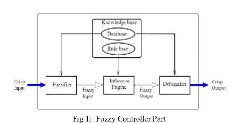
Список литературы Design Modified Fuzzy Hybrid Technique: Tuning By GDO
- G. Robinson, and J. Davies, “Continuum robots – a state of the art,”Proc. IEEE International Conference on Robotics and Automation, Detroit, MI, 1999, vol. 4, pp. 2849-2854.
- I.D. Walker, D. Dawson, T. Flash, F. Grasso, R. Hanlon, B. Hochner, W.M. Kier, C. Pagano,C.D. Rahn, Q. Zhang, “Continuum Robot Arms Inspired by Cephalopods, Proceedings SPIE Conference on Unmanned Ground Vehicle Technology VII, Orlando, FL, pp 303-314, 2005.
- K. Suzumori, S. Iikura, and H. Tanaka, “Development of Flexible Microactuator and it’s Applications to Robotic Mechanisms”, Proceedings IEEE International Conference on Robotics and Automation, Sacramento, California, pp. 1622-1627, 1991.
- D. Trivedi, C.D. Rahn, W.M. Kier, and I.D. Walker, “Soft Robotics: Biological Inspiration, State of the Art, and Future Research”, Applied Bionics and Biomechanics, 5(2), pp. 99-117, 2008.
- W. McMahan, M. Pritts, V. Chitrakaran, D. Dienno, M. Grissom, B. Jones, M. Csencsits, C.D. Rahn, D. Dawson, and I.D. Walker, “Field Trials and Testing of “OCTARM” Continuum Robots”, Proc. IEEE International Conference on Robotics and Automation, pp. 2336-2341, 2006.
- W. McMahan, I.D. Walker, “Octopus-Inspired Grasp Synergies for Continuum Manipulators”, Proc. IEEE International Conference on Robotics and Biomimetics, pp. 945- 950, 2009.
- I. Boiko, L. Fridman, A. Pisano and E. Usai, "Analysis of chattering in systems with second-order sliding modes," IEEE Transactions on Automatic Control, No. 11, vol. 52,pp. 2085-2102, 2007.
- J. Wang, A. Rad and P. Chan, "Indirect adaptive fuzzy sliding mode control: Part I: fuzzy switching," Fuzzy Sets and Systems, No. 1, vol. 122,pp. 21-30, 2001.
- M. Bazregar, Farzin Piltan, A. Nabaee and M.M. Ebrahimi, “Parallel Soft Computing Control Optimization Algorithm for Uncertainty Dynamic Systems”, International Journal of Advanced Science and Technology, 51, 2013.
- Farzin Piltan, M.H. Yarmahmoudi, M. Mirzaei, S. Emamzadeh, Z. Hivand, “Design Novel Fuzzy Robust Feedback Linearization Control with Application to Robot Manipulator”, International Journal of Intelligent Systems and Applications, 5(5), 2013.
- Sh. Tayebi Haghighi, S. Soltani, Farzin Piltan, M. kamgari, S. Zare, “Evaluation Performance of IC Engine: Linear Tunable Gain Computed Torque Controller Vs. Sliding Mode Controller”, International Journal of Intelligent Systems and Applications, 5(6), 2013.
- Farzin Piltan, A. R. Salehi & Nasri B Sulaiman,“Design Artificial Robust Control of Second Order System Based on Adaptive Fuzzy Gain Scheduling”, World Applied Science Journal (WASJ), 13 (5): 1085-1092, 2011.
- Farzin Piltan, N. Sulaiman, Atefeh Gavahian, Samira Soltani & Samaneh Roosta, “Design Mathematical Tunable Gain PID-Like Sliding Mode Fuzzy Controller with Minimum Rule Base”, International Journal of Robotic and Automation, 2 (3): 146-156, 2011.
- Farzin Piltan , N. Sulaiman, Zahra Tajpaykar, Payman Ferdosali & Mehdi Rashidi, “Design Artificial Nonlinear Robust Controller Based on CTLC and FSMC with Tunable Gain”, International Journal of Robotic and Automation, 2 (3): 205-220, 2011.
- Farzin Piltan, Mohammad Mansoorzadeh, Saeed Zare, Fatemeh Shahriarzadeh, Mehdi Akbari, “Artificial tune of fuel ratio: Design a novel siso fuzzy backstepping adaptive variable structure control”, International Journal of Electrical and Computer Engineering (IJECE), 3 (2): 183-204, 2013.
- Farzin Piltan, M. Bazregar, M. Kamgari, M. Akbari, M. Piran, “Adjust the fuel ratio by high impact chattering free sliding methodology with application to automotive engine”, International Journal of Hybrid Information Technology (IJHIT), 6 (1): 13-24, 2013.
- Shahnaz Tayebi Haghighi, S. Soltani, Farzin Piltan, M. Kamgari, S. Zare, “Evaluation Performance of IC Engine: linear tunable gain computed torque controller Vs. Sliding mode controller”, I. J. Intelligent system and application, 6 (6): 78-88, 2013.
- Farzin Piltan, N. Sulaiman, Payman Ferdosali & Iraj Assadi Talooki, “Design Model Free Fuzzy Sliding Mode Control: Applied to Internal Combustion Engine”, International Journal of Engineering, 5 (4):302-312, 2011.
- Farzin Piltan, N. Sulaiman, A. Jalali & F. Danesh Narouei, “Design of Model Free Adaptive Fuzzy Computed Torque Controller: Applied to Nonlinear Second Order System”, International Journal of Robotics and Automation, 2 (4):245-257, 2011
- A. Jalali, Farzin Piltan, M. Keshtgar, M. Jalali, “Colonial Competitive Optimization Sliding Mode Controller with Application to Robot Manipulator”, International Journal of Intelligent Systems and Applications, 5(7), 2013.
- Farzin Piltan, Amin Jalali, N. Sulaiman, Atefeh Gavahian & Sobhan Siamak, “Novel Artificial Control of Nonlinear Uncertain System: Design a Novel Modified PSO SISO Lyapunov Based Fuzzy Sliding Mode Algorithm”, International Journal of Robotics and Automation, 2 (5): 298-316, 2011.
- Farzin Piltan, N. Sulaiman, Iraj Asadi Talooki & Payman Ferdosali, “Control of IC Engine: Design a Novel MIMO Fuzzy Backstepping Adaptive Based Fuzzy Estimator Variable Structure Control”, International Journal of Robotics and Automation, 2 (5):360-380, 2011.
- Farzin Piltan, N. Sulaiman, S.Soltani, M. H. Marhaban & R. Ramli, “An Adaptive Sliding Surface Slope Adjustment in PD Sliding Mode Fuzzy Control For Robot Manipulator”, International Journal of Control and Automation, 4 (3): 65-76, 2011.
- Farzin Piltan, N. Sulaiman, Mehdi Rashidi, Zahra Tajpaikar & Payman Ferdosali, “Design and Implementation of Sliding Mode Algorithm: Applied to Robot Manipulator-A Review”, International Journal of Robotics and Automation, 2 (5):265-282, 2011.
- Farzin Piltan, N. Sulaiman , Arash Zargari, Mohammad Keshavarz & Ali Badri, “Design PID-Like Fuzzy Controller with Minimum Rule Base and Mathematical Proposed On-line Tunable Gain: Applied to Robot Manipulator”, International Journal of Artificial Intelligence and Expert System, 2 (4):184-195, 2011.
- Farzin Piltan, SH. Tayebi HAGHIGHI, N. Sulaiman, Iman Nazari & Sobhan Siamak, “Artificial Control of PUMA Robot Manipulator: A-Review of Fuzzy Inference Engine and Application to Classical Controller”, International Journal of Robotics and Automation, 2 (5):401-425, 2011.
- A. Salehi, Farzin Piltan, M. Mousavi, A. Khajeh, M. R. Rashidian, “Intelligent Robust Feed-forward Fuzzy Feedback Linearization Estimation of PID Control with Application to Continuum Robot”, International Journal of Information Engineering and Electronic Business, 5(1), 2013.
- Farzin Piltan, N. Sulaiman & I.AsadiTalooki, “Evolutionary Design on-line Sliding Fuzzy Gain Scheduling Sliding Mode Algorithm: Applied to Internal Combustion Engine”, International Journal of Engineering Science and Technology, 3 (10):7301-7308, 2011.
- Farzin Piltan, Nasri B Sulaiman, Iraj Asadi Talooki & Payman Ferdosali, ”Designing On-Line Tunable Gain Fuzzy Sliding Mode Controller Using Sliding Mode Fuzzy Algorithm: Applied to Internal Combustion Engine” World Applied Science Journal (WASJ), 15 (3): 422-428, 2011.
- Farzin Piltan, M.J. Rafaati, F. Khazaeni, A. Hosainpour, S. Soltani, “A Design High Impact Lyapunov Fuzzy PD-Plus-Gravity Controller with Application to Rigid Manipulator”, International Journal of Information Engineering and Electronic Business, 5(1), 2013.
- A. Jalali, Farzin Piltan, A. Gavahian, M. Jalali, M. Adibi, “Model-Free Adaptive Fuzzy Sliding Mode Controller Optimized by Particle Swarm for Robot manipulator”, International Journal of Information Engineering and Electronic Business, 5(1), 2013.
- Farzin Piltan, N. Sulaiman, Payman Ferdosali, Mehdi Rashidi & Zahra Tajpeikar, “Adaptive MIMO Fuzzy Compensate Fuzzy Sliding Mode Algorithm: Applied to Second Order Nonlinear System”, International Journal of Engineering, 5 (5): 380-398, 2011.
- Farzin Piltan, N. Sulaiman, Hajar Nasiri, Sadeq Allahdadi & Mohammad A. Bairami, “Novel Robot Manipulator Adaptive Artificial Control: Design a Novel SISO Adaptive Fuzzy Sliding Algorithm Inverse Dynamic Like Method”, International Journal of Engineering, 5 (5): 399-418, 2011.
- Farzin Piltan, N. Sulaiman, Sadeq Allahdadi, Mohammadali Dialame & Abbas Zare, “Position Control of Robot Manipulator: Design a Novel SISO Adaptive Sliding Mode Fuzzy PD Fuzzy Sliding Mode Control”, International Journal of Artificial Intelligence and Expert System, 2 (5):208-228, 2011.
- M. M. Ebrahimit Farzin Piltan, M. Bazregar and A.R. Nabaee “Intelligent Robust Fuzzy-Parallel Optimization Control of a Continuum Robot Manipulator”, International Journal of Control and Automation, 6(3), 2013.
- Farzin Piltan, M.A. Bairami, F. Aghayari, M.R. Rashidian, “Stable Fuzzy PD Control with Parallel Sliding Mode Compensation with Application to Rigid Manipulator”, International Journal of Information Technology and Computer Science, 5(7), 2013.
- Farzin Piltan, N. Sulaiman, Samaneh Roosta, Atefeh Gavahian & Samira Soltani, “Evolutionary Design of Backstepping Artificial Sliding Mode Based Position Algorithm: Applied to Robot Manipulator”, International Journal of Engineering, 5 (5):419-434, 2011.
- Farzin Piltan, N. Sulaiman, Amin Jalali, Sobhan Siamak & Iman Nazari, “Control of Robot Manipulator: Design a Novel Tuning MIMO Fuzzy Backstepping Adaptive Based Fuzzy Estimator Variable Structure Control”, International Journal of Control and Automation, 4 (4):91-110, 2011.
- Farzin Piltan, N. Sulaiman, Atefeh Gavahian, Samaneh Roosta & Samira Soltani, “On line Tuning Premise and Consequence FIS: Design Fuzzy Adaptive Fuzzy Sliding Mode Controller Based on Lyaponuv Theory”, International Journal of Robotics and Automation, 2 (5):381-400, 2011.
- Farzin Piltan, N. Sulaiman, Samira Soltani, Samaneh Roosta & Atefeh Gavahian, “Artificial Chattering Free on-line Fuzzy Sliding Mode Algorithm for Uncertain System: Applied in Robot Manipulator”, International Journal of Engineering, 5 (5):360-379, 2011.
- Farzin Piltan, F. ShahryarZadeh, M. Mansoorzadeh, M. kamgari, S. Zare, “Robust Fuzzy PD Method with Parallel Computed Fuel Ratio Estimation Applied to Automotive Engine “International Journal of Intelligent Systems and Applications, 5(8), 2013.
- Farzin Piltan, Sadeq Allahdadi, Mohammad A.Bairami & Hajar Nasiri, “Design Auto Adjust Sliding Surface Slope: Applied to Robot Manipulator”, International Journal of Robotics and Automation, 3 (1):27-44, 2011.
- Farzin Piltan, Mohammadali Dialame, Abbas Zare & Ali Badri, “Design Novel Lookup Table Changed Auto Tuning FSMC:Applied to Robot Manipulator”, International Journal of Engineering, 6 (1):25-41, 2012.
- Farzin Piltan, M. Keshavarz, A. Badri & A. Zargari, “Design Novel Nonlinear Controller Applied to RobotManipulator: Design New Feedback Linearization Fuzzy Controller with Minimum Rule Base Tuning Method”, International Journal of Robotics and Automation, 3 (1):1-12, 2012.
- Farzin Piltan, Mohammad A.Bairami, Farid Aghayari & Sadeq Allahdadi, “Design Adaptive Artificial Inverse Dynamic Controller: Design Sliding Mode Fuzzy Adaptive New Inverse Dynamic Fuzzy Controller”, International Journal of Robotics and Automation, (1):13-26, 2012.
- Farzin Piltan, Sadeq Allahdadi, Mohammad A.Bairami & Hajar Nasiri, “Design Auto Adjust Sliding Surface Slope: Applied to Robot Manipulator”, International Journal of Robotics and Automation, 3 (1):27-44, 2012.
- Farzin Piltan, F. Aghayari, M. Rashidian & M. Shamsodini, “A New Estimate Sliding Mode Fuzzy Controller for RoboticManipulator”, International Journal of Robotics and Automation, 3 (1):45-60, 2012
- Farzin Piltan, Iman Nazari, Sobhan Siamak, Payman Ferdosali, “Methodology of FPGA-Based Mathematical error-Based Tuning Sliding Mode Controller”, International Journal of Control and Automation, 5(1), 89-118, 2012.
- Farzin Piltan, Bamdad Boroomand, Arman Jahed & Hossein Rezaie, “Methodology of Mathematical Error-Based Tuning Sliding Mode Controller”, International Journal of Engineering, 6 (2):96-117, 2012.
- Farzin Piltan, S. Emamzadeh, Z. Hivand, F. Shahriyari & Mina Mirazaei. ” PUMA-560 Robot Manipulator Position Sliding Mode Control Methods Using MATLAB/SIMULINK and Their Integration into Graduate/Undergraduate Nonlinear Control, Robotics and MATLAB Courses”, International Journal of Robotics and Automation, 3(3):106-150, 2012.
- Farzin Piltan, A. Hosainpour, E. Mazlomian, M.Shamsodini, M.H Yarmahmoudi. ”Online Tuning Chattering Free Sliding Mode Fuzzy Control Design: Lyapunov Approach”, International Journal of Robotics and Automation, 3(3):77-105, 2012.
- Farzin Piltan, R. Bayat, F. Aghayari, B. Boroomand. “Design Error-Based Linear Model-Free Evaluation Performance Computed Torque Controller”, International Journal of Robotics and Automation, 3(3):151-166, 2012.
- Farzin Piltan, J. Meigolinedjad, S. Mehrara, S. Rahmdel. ”Evaluation Performance of 2nd Order Nonlinear System: Baseline Control Tunable Gain Sliding Mode Methodology”, International Journal of Robotics and Automation, 3(3): 192-211, 2012.
- Farzin Piltan, Mina Mirzaei, Forouzan Shahriari, Iman Nazari, Sara Emamzadeh, “Design Baseline Computed Torque Controller”, International Journal of Engineering, 6(3): 129-141, 2012.
- Farzin Piltan, Sajad Rahmdel, Saleh Mehrara, Reza Bayat , “Sliding Mode Methodology Vs. Computed Torque Methodology Using MATLAB/SIMULINK and Their Integration into Graduate Nonlinear Control Courses” , International Journal of Engineering, 6(3): 142-177, 2012.
- Farzin Piltan , M.H. Yarmahmoudi, M. Shamsodini, E.Mazlomian, A.Hosainpour. ”PUMA-560 Robot Manipulator Position Computed Torque Control Methods Using MATLAB/SIMULINK and Their Integration into Graduate Nonlinear Control and MATLAB Courses”, International Journal of Robotics and Automation, 3(3): 167-191, 2012.
- Farzin Piltan, Hossein Rezaie, Bamdad Boroomand, Arman Jahed. “Design Robust Backstepping on-line Tuning Feedback Linearization Control Applied to IC Engine”, International Journal of Advance Science and Technology, 11:40-22, 2012.
- Farzin Piltan, S. Siamak, M.A. Bairami and I. Nazari. ” Gradient Descent Optimal Chattering Free Sliding Mode Fuzzy Control Design: Lyapunov Approach”, International Journal of Advanced Science and Technology, 43: 73-90, 2012.
- Farzin Piltan, M.R. Rashidian, M. Shamsodini and S. Allahdadi. ” Effect of Rule Base on the Fuzzy-Based Tuning Fuzzy Sliding Mode Controller: Applied to 2nd Order Nonlinear System”, International Journal of Advanced Science and Technology, 46:39-70, 2012.
- Farzin Piltan, A. Jahed, H. Rezaie and B. Boroomand. ” Methodology of Robust Linear On-line High Speed Tuning for Stable Sliding Mode Controller: Applied to Nonlinear System”, International Journal of Control and Automation, 5(3): 217-236, 2012.
- Farzin Piltan, R. Bayat, S. Mehara and J. Meigolinedjad. ”GDO Artificial Intelligence-Based Switching PID Baseline Feedback Linearization Method: Controlled PUMA Workspace”, International Journal of Information Engineering and Electronic Business, 5: 17-26, 2012.
- Farzin Piltan, B. Boroomand, A. Jahed and H. Rezaie. ”Performance-Based Adaptive Gradient Descent Optimal Coefficient Fuzzy Sliding Mode Methodology”, International Journal of Intelligent Systems and Applications, 11: 40-52 2012.
- Farzin Piltan, S. Mehrara, R. Bayat and S. Rahmdel. ” Design New Control Methodology of Industrial Robot Manipulator: Sliding Mode Baseline Methodology”, International Journal of Hybrid Information Technology, 5(4):41-54, 2012.
- AH Aryanfar, MR Khammar, Farzin Piltan, “Design a robust self-tuning fuzzy sliding mode control for second order systems”, International Journal of Engineering Science REsearch, 3(4): 711-717, 2012.
- Farzin Piltan, Shahnaz Tayebi Haghighi, “Design Gradient Descent Optimal Sliding Mode Control of Continuum Robots”, International Journal of Robotics and Automation, 1(4): 175-189, 2012.
- Farzin Piltan, A. Nabaee, M.M. Ebrahimi, M. Bazregar, “Design Robust Fuzzy Sliding Mode Control Technique for Robot Manipulator Systems with Modeling Uncertainties”, International Journal of Information Technology and Computer Science, 5(8), 2013.
- Farzin Piltan, M. Akbari, M. Piran , M. Bazregar. ”Design Model Free Switching Gain Scheduling Baseline Controller with Application to Automotive Engine”, International Journal of Information Technology and Computer Science, 01:65-73, 2013.
- Farzin Piltan, M. Piran , M. Bazregar, M. Akbari, “Design High Impact Fuzzy Baseline Variable Structure Methodology to Artificial Adjust Fuel Ratio”, International Journal of Intelligent Systems and Applications, 02: 59-70, 2013.
- Farzin Piltan, M. Mansoorzadeh, M. Akbari, S. Zare, F. ShahryarZadeh “Management of Environmental Pollution by Intelligent Control of Fuel in an Internal Combustion Engine“ Global Journal of Biodiversity Science And Management, 3(1), 2013.
