Design Novel Model Reference Artificial Intelligence Based Methodology to Optimized Fuel Ratio in IC Engine

Author: FarzinPiltan,MarziehKamgari, SaeedZare, FatemehShahryarZadeh, Mohammad Mansoorzadeh
Journal: International Journal of Information Engineering and Electronic Business(IJIEEB) @ijieeb
Article in issue: 2 vol.5, 2013.
Free access
In this research, model reference fuzzy based control is presented as robust controls for IC engine. The objective of the study is to design controls for IC engines without the knowledge of the boundary of uncertainties and dynamic information by using fuzzy model reference PD plus mass of air while improve the robustness of the PD plus mass of air control. A PD plus mass of air provides for eliminate the mass of air and ultimate accuracy in the presence of the bounded disturbance/uncertainties, although this methods also causes some oscillation. The fuzzy PD plus mass of air is proposed as a solution to the problems crated by unstability. This method has a good performance in presence of uncertainty.
PD plus mass of air, model reference fuzzy logic theory, fuzzy PD plus mass of air method, IC engine, stability, robustness
Short address: https://sciup.org/15013178
IDR: 15013178
Text of the scientific article Design Novel Model Reference Artificial Intelligence Based Methodology to Optimized Fuel Ratio in IC Engine
Published Online August 2013 in MECS (http://www.
Automotive internal combustion (IC) engines are designed to produce power from the energy that is contained in their fuel. More specifically, their fuel contains energy and together with air, this mixture ignites to output useable mechanical power. There are several types of fuels as well as combustion types that can be used in automotive IC engines, all of which must be controlled to optimize the fuel that is used by the engine, maximize the power that will be used to operate the vehicle, and reduce the harmful gases that are produced from the combustion. As discussed in the previous research, control systems engineering applications employ the use of engine models to aid in controls design, optimization and evaluation [1-3]. For performance applications, the one-dimensional simulation technique has become the industry standard, while for large scale control studies and optimizations, the zero dimensional cycle resolve model is the prevalent choice. In developing a valid engine model of spark-ignition engines, the concept of the combustion process must be understood. The combustion process is relatively simple and it begins with fuel and air being mixed together in the intake manifold and cylinder. This air-fuel mixture is trapped inside the cylinder after the intake valve(s) is closed and then gets compressed [4-8]. Air-to-fuel (A/F) ratio is the mass ratio of air and fuel trapped inside the cylinder of an engine before combustion starts. When all of the fuel in the cylinder is combined with all of the oxygen in the combustion chamber (cylinder), the mixture of air and fuel is a stoichiometric mixture [9-10].There are two basic methods of dealing with control problems, the linear methodology and the nonlinear methodology. Strictly speaking, linear systems do not exist in practice, since all physical systems are nonlinear. However, the great majority of control algorithms are designed assuming linear behavior [11]. To make linear methodologies work, the key assumption is to assume a linear characteristics over a small range of operation. This enables the designer to obtain a linearized version of a nonlinear system model. But, there are numerous control situations in which the linear control system fails to meet the requirements, for instance, systems with large parameter variations or when the state of the system is far from the linearization point [12-15]. The parameter variations and nonlinearities can degrade system performance and possibly destabilize the system. In addition, the nonlinearities called hard nonlinearities, such as motor pressure, engine angular speed saturation, matrix mass of air in cylinder and large variations in loads and tasks. Possess discontinuous features that do not lend themselves to linear approximation. Usually, such nonlinear characteristics have undesirable effects on the performance of the systems under investigation and control systems have to be designed to compensate for them. Considering linear and nonlinear control methodologies the nonlinear ones are more general since they can be successfully applied to linear systems whereas a linear controller might be insufficient for control of a nonlinear system [16-20]. It is worthy to note that, .more recently, there has been a growing interest among researchers in new types of controllers which can combine the approximation power of computational-intelligence techniques (e.g., fuzzy logic and neural networks) with the simplicity of the most commonly used linear controller called three-term or proportional-integral-derivative (PID) controller [21-24]. The complexity of nonlinear uncertain systems challenges a control system designer to come up with a unified systematic design procedure to meet the control objectives (e.g., stability and robustness) and design specifications. Faced with such challenges, an investigation of different nonlinear uncertain systems has made it clear that the designer cannot expect one particular procedure be applicable to all nonlinear uncertain systems [25-29]. A multitude of nonlinear control laws have been developed called "computed-fuel ratio " or "inverse dynamic" controller in the IC engine literature. These controllers incorporate the inverse dynamic model of IC engine to construct model-based controller. The computed fuel ratio controllers have their root in feedback linearization control methodology. The idea is to design a nonlinear feedback (maybe calculated using the inverse dynamic model of the IC engine to be controlled) which cancels the nonlinearities of an actual IC engine. In this manner the closed-loop system becomes exactly linear or partly linear depending on the accuracy of the dynamic model, and then a linear controller such as PD and PID can be applied to control the IC engine [30-31]. Due to the fact that parameters errors are not the sole source of imperfect decoupling and linearization of the IC engine dynamics, thus this control methodology cannot provide robustness against external unstructured uncertainties. Another difficulty that may be encountered in the implement of computed-Fuel ratio control is that the entire dynamic model (the mass of air matrix, the pressure of motor, engine angular speed and mass of air in cylinder) of the IC engine, since control is now based on the nonlinear feedback of the current system state. For an IC engine these computations can be complicated and time consuming. The problem of computation burden can even be increased when the adaptive computed-fuel ratio control is used. This is due to extra computation needed to update the parameters in each sample time. Two methods can be found in the literature to deal with the problem of computation burden described above. One method to deal with the problem of computation burden is to use feed forward computed-fuel ratio control in which the PFI and DI vectors are computed on the basis of the desired measure of the fuel and computed-fuel ratio compensates the nonlinear coupling effects [18-19]. As opposed to feedback computed-fuel ratio control, in the feedforward method it is possible to pre-compute all the terms of the dynamic model off-line and reduce the computation burden to a large extent. The second method to deal with the problem of heavy computation burden in the computed-fuel ratio control is to develop a computationally efficient dynamic model by mass of air in PD method. As mentioned in above, the IC engines are inherently complex and nonlinear uncertain systems with human-like behavior [10-12]. Since fuzzy systems are able to mimic the human approach for controlling and optimizing the systems, these systems can be a valuable tool for modeling the Complex dynamics or inverse dynamics of IC engine in order 10 build a model-based robust controller. Very often tile approximation capabilities of the fuzzy systems are used for compensating the unknown dynamics or particular component of the dynamics of a system. Therefore, the goal is to develop a controller similar to the human brain. Based on the extensive literature review it was found that various controls with various control methodologies to reduce the error. The combination not only encompasses the features and capabilities of its components (i.e., different control methodologies) but also the limitations attributed to these techniques may be remedied by each other. Therefore, a combined nonlinear robust control methodology is selected to deal with the control of IC engine in the presence of uncertainties. The research described in this paper focuses on the synthesis, design, analysis (i.e., stability and robust analysis) and implementation of this combined nonlinear robust controller. The robust is selected as a framework to synthesize the controller, since the PD plus mass of air methodologies have proven very effective in a variety of practical control of, IC engines [1-8].
One of the most significant challenges in control algorithms is a linear behavior controller design for nonlinear systems (e.g., IC engine). Some of IC engines are controlled by linear PID controllers, but the designs of linear controller for these systems are extremely difficult because they are hardly nonlinear and uncertain. To reduce the above challenges, the nonlinear robust controller is used to control of IC engine. PD plus mass of air is a nonlinear controller. Parallel fuzzy PD plus mass of air controller is used to control of highly nonlinear systems especially for IC engines. Estimate nonlinear equivalent dynamic formulation in uncertain dynamic parameter is the main drawback in pure PD plus mass of air controller. The nonlinear equivalent dynamic formulation problem in uncertain system is solved by using fuzzy logic theorem. Fuzzy logic theory is used to estimate the system’s dynamics. This methodology is based on applied fuzzy logic in PD plus mass of air to estimate the nonlinear term of IC engine.
This paper is organized as follows: In section 2, main subject of modeling IC engine formulation and fuzzy logic method are presented. Detail of proposed methodology is presented in section 3. In section 4, the simulation result is presented and finally in section 5, the conclusion is presented.
II. THEORY 2.1 Case study:Dynamic Formulation of IC Engine
Dynamic equation is the study of motion with regard to forces. Dynamic modeling is vital for control,
46 Design Novel Model Reference Artificial Intelligence Based Methodology to Optimized Fuel
Ratio in IC Engine
mechanical design, and simulation. It is used to describe dynamic parameters and also to describe the relationship between PFI and DI to force acting on IC engine. Several different methods are available to compute IC engine dynamic equations. These methods include the Newton-Euler (N-E) methodology, the Lagrange-Euler (L-E) method, and Kane’s methodology [1]. The Newton-Euler methodology is based on Newton’s second law and several different researchers are signifying to develop this method [1, 14]. This equation can be described the behavior of a IC engine step by step, called forward recursion and transfer the essential information from PFI and DI to fuel ratio, called backward recursive. The literature on Euler-Lagrange’s is vast but a good starting point to learn about it is in[1]. Calculate the dynamic equation IC engine using E-L method is easier because this equation is derivation of nonlinear coupled and quadratic differential equations. The Kane’s method was introduced in 1961 by Professor Thomas Kane[1, 6]. This method used to calculate the dynamic equation of motion without any differentiation between kinetic and potential energy functions.
Dynamic modeling of IC engine is used to describe the nonlinear behavior of IC engine, design of model based controller such as pure variable structure controller based on nonlinear dynamic equations, and for simulation. The dynamic modeling describes the relationship between fuel to air ratio to PFI and DI and also it can be used to describe the particular dynamic effects (e.g., motor pressure, angular speed, mass of air in cylinder, and the other parameters) to behavior of system[1].
The equation of an IC engine governed by the following equation [1-4]:
ГPFI1 ГМ air 11 Ml air 12] [FR1 , [P motor 11 r„.„ . 1 ,
I DI J = к „,, Й . I1 J + P R " ' 1 +
N 11 N 12 FR 2 M a1
К N ,, 1 X 1 d i 1 + 1M a 2 J (1)
Where PFI is port fuel injector, DI is direct injector, Mair is a symmetric and positive define mass of air matrix, Pmotor is the pressure of motor, N is engine angular speed and Ma is matrix mass of air in cylinder. Fuel ratio and exhaust angle are calculated by [2,5, 9]:
I 9=
Mair 11
M.
-1
air 12
■ Mair 21
M air 22
Iffl-lfTli"......
ui motor 2J
+
" Nn
N 12
- N21
N 22
The above target equivalence ratio calculation will be combined with fuel ratio calculation that will be used for controller design purpose.
2.2 Fuzzy Logic Methodology
Zadeh introduced fuzzy sets in 1965. After about 50 years, fuzzy systems have been widely used in different fields, especially on control problems. Fuzzy systems transfer expert knowledge to mathematical models. Fuzzy systems use fuzzy logic to estimate dynamics of our systems. Fuzzy controllers including fuzzy if-then rules are used to control IC engines [1620]. Conventional control methods use mathematical models to control systems. Fuzzy control methods replace the mathematical models with fuzzy if-then rules and fuzzy membership functions to control systems. Both fuzzy and conventional control methods are designed to meet system requirements of stability and convergence. When mathematical models are unknown or partially unknown, fuzzy control methods can use fuzzy systems to estimate the unknown models. This is called the model-free approach. Conventional control methods can use adaptive control methods to achieve the model free approach. When system dynamics become more complex, nonlinear systems are difficult to handle, by conventional control methods. From the universal approximation theorem in below, fuzzy systems can approximate arbitrary nonlinear systems [21-23].
SUP xeu V (x) -g (x)|< e (3)
In practical problems, systems can be controlled perfectly by experts. Experts provide linguistic description about systems. Conventional control methods cannot design controllers combined with linguistic information. When linguistic information is important for designing controllers, we need to design fuzzy controllers for our systems. Fuzzy control methods are easy to understand for designers. The design process of fuzzy controllers can be simplified with simple mathematical models. A whole fuzzy system includes four components: fuzzy rule base, fuzzy inference engine, fuzzifier and defuzzifier. Figure 1 shows the fuzzy system where inputs and outputs are real-valued variables. We introduce Mamdani fuzzy inference systems as our fuzzy inference engines. Mamdani fuzzy inference systems use algebraic product base on (2) as our T-norm operators and max-product composition in (4) as our composition operators [24].
Algebraic product: Tab (a , b) = ab (4)
ц !B (y) = шах[Ц д (x)^ R (x,y)] = V,, [цА (х)|^(х,у)]
Premise 1 (rule 1): if x 1 is A1 and x 2 is A1 then (6) у is В 1
Premise 2 (rule2): if x 1 is A1 and x2 is A2 then у is В2
Premise 3 (fact): if x1 is A1 and x2 is A 2
Conclusion: у is В
В'= [(/1 X /2)°(/1 X /11 ^ В 1)] и [(/1 X /2)°(/1 X /2 ^ В 2)] = [(/ X /2)°R1 ] и [(/1 X /2 ) °R2] = defuzzifier, we use its approximation: the center average defuzzifier.
В1 и В 2
Based on the two rules with two antecedents in (4), we use max-product composition for the operator and maximum operation for the U operator in (5). The membership function of fuzzy set B' is given by
. в (У)
= max2 l=1 max x1,x2
I / 1 (X 1 )1 / 2 (X 2 ) ^ . / (X t ) .Bi (у)
1=1
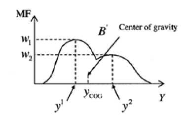
Figure2: Defuzzification of fuzzy set B'
A fuzzifier is defined as a mapping from a real-valued crisp point X * to a fuzzy set
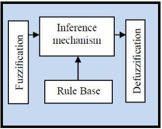
Figure 1 : Basic configuration of fuzzy systems
At To simplify the computation in (6), we introduce the singleton fuzzifier:
The center average deFuzzifier is defined as
52=1 у1. в1 (у1) уС0С = y2 „ л л n
-
5 l =1 . В 1 (У )
5 l=1 У1” 1
5 l=1 w l
Where у1 and у2 are the centers of В 1 and В 2 in (5); w 1 = . B 1 (У 1 ) and w2 = . в2 (У2) are shown in Figure 2. If all fuzzy membership functions are symmetric, we can get: у1 and У 2 are the centers of B 1 and B2 ; w 1 and w2 are the heights of fuzzy set В related to у1 and y2 . We derive the membership function of the fuzzy set B i at the point У1 from (8). We can get .B l (у1 ) = .^ (X*). / (x2)iib i (У1 ) . Assume the fuzzy set Bl is normal, we get цВ1 (У1 ) = 1 . The membership function of the fuzzy set Bl at the point у 1 becomes цВ, (У1 )= .л (x 1 )|Z. l (х 2 ) . Equation (10) l / 1 / 2
becomes
. / (X ) = {0
tfX i = X *( t = 1,2) others
5 2=1 у1.в1(у1)
У с/ = 5 2=1 . в1 (У)
Since, ./ 1 (x 1 ) = ./ 2 (x * ) = 1 , we can reduce (6) into:
.в (У) = max21=1 [П2=1 ^i (X* ).Bi (У) ]= max2i=1 [.в1 (У)]
In (8), the output B' is a fuzzy set with the membership function . в (у) . To use a fuzzy system as a controller, we need a crisp output. We use a defuzzifier to map a fuzzy set to a single point. We introduce two defuzzifiers: center of gravity dcfuzzifier and center average defuzzifier [25-28].
The center of gravity defuzzifier is defined as
5 2=1 у1[п2=1 . /l (x * ) ] 52=1|п2=1 . /l (x * ) ]
III. METHODOLOGY
A useful family of computed fuel ratio controller (CFC) is PD plus mass of air which the results when
M air 11
M1 air 21
M air12
air22
]=;, n =[M a1 ]• Based
on CFC
method and uncertainty in dynamic formulation, this
method is defined by the following formulation;
PFI
[ DI]
M air 11 M air 12
M air 21 M air 22
_ jy y.R (У)dy
УС0С i y I B (У )й У
M
( FRd + Kve + Kpe) + [Ma 1 ]
If the follows;
Lyapunov function in this method defined as
Figure (2) shows the centroid of area B'. We can get the point уС0С on Y axis. Since the membership function I В (У) is usually irregular, the integrations in (9) are difficult to compute. Instead of the center of gravity
M air 11 M air 12
M air 21 M air 22
V =
] X FRT x F'R^ + (eTKpe)
and the differentiate to obtain
M v(frt) I • V Ml,
air 11
1 f'r[ M
2 |м
air11
air21
air 21
м air 12
м air 22
М ■ air 12
м air 22
] х FR +
] - Kp^
This methodology has three main parts; linear PD part based on PD linear formulation, nonlinear mass of airpart to eliminate the term of mass of air and fuzzy like nonlinear equivalent part to eliminate the nonlinearity part. Based on this methodology;
г.
Based on CFC formulation and Lyapunov formulation in CFC;
-Гм М . гР 1
V = (^й "** а"“ - ([p *llFRdJ +
Mair 21 Mair 22 mo tor 2
К** N * 2] х [PRT+[M a* ]+[M a* ])хFR =
Iaa
FRTKVFR (17)
Therefore the skew symmetry of the first term is given by;
[PPI1 = [M, DIJ = №
air 11
air 21
[M a* ]+^ ^t
M air 12
Ml air 22
<(X )
(FRd + Kve + kpc) +
If the Lyapunov function in this method defined as follows;
V=
air 11
M air 21
2 S M=* Y j ФТ.Ф )
M air 12
M air 22
] х FRT х PR) + (e T K p e) +
V = -FRTKVFR
and the differentiate to obtain
Based on above formulation this methodology has demonstrate stability in the sense of Lyapunov in bounded of error and joint velocity when V is negative.The method of computed torque control works quite well, and we can have better control than linear PD or PID control, but only if we have all necessary information about nonlinear dynamic formulation of system and the parameters of IC engine. These are very hard to have in practice. At the same time, the dynamics of the IC engine can change during the process, and that can affect the result of the control, too. In this case the result of CFC can decrease because the inquiry of dynamic model. To avoid of this situation fuzzy logic method can applied to PD plus mass of air method to estimate uncertainty and nonlinear part which it is caused to reduce the performance quality. In this case we can achieve the desired settling time and we can achieve very small steady state tracking errors. Based on fuzzy logic methodology
f(x) = ufuzzy = Z f.* 0T < to (19)
where 6T is adjustable parameter (gain updating factor) and ^(x) is defined by
S f ^ (r i )
Where /z(x,-) is membership function. T ^ uzzy is defined as follows;
r^z, = S=* eTfW = [P”“ 1][FR6|] + motor 2
[N ** N*^ [FR]2 (21)
VI =
(>«([M
air 11
M
M
air 21
„*,
air 11
air21
M ■ air 12
M ■ air 22
M ■ air 12
M ■ air 22
х PR +
] — K p e)+ s m =* Y" ф
Based on (14) and (15);
[N ** N *2
N 21 N 22
'T. 4> j
M air11
air 21
M ■ air 12
M ■ air22
]- ([P m^* ][FRd i l + motor 2
] х [FR]2 + [M a* ]+[M a* ])xpr+
I
a2
a2
SM-i - фт. ф), = PRTKVPR + SM-i -фт. Ф
J Y j j J Y j j
Y j
Therefore the skew symmetry of the first term is given by;
V = -FR T K v FR - 1 ]=* - фт. ф) j (26)
Y j
IV. RESULTS AND DISCUSSION
Proposed fuzzy PD plus mass of air control (proposed) and PD plus mass of air controller (PDM) was used to decrease the error and increase the efficiency of FR method. This design was implemented in MATLAB/SIMULINK environment. Fuel ratio adjustment is used to test the stability in certain environment. Disturbance rejection test is used to test the stability and robustness in presence of uncertainty.
Adjust the fuel ratio: based on proposed formulation in PD plus mass of air method and fuzzy PD plus mass of air method; the performances of these controllers are depended on the PD ( Kp aruiKV ) and gain updating factor
coefficients. These factors are calculated by optimization method.
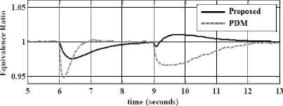
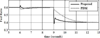
Figure3 : Fuel adjusts performance; fuzzy PD mass of air methodology and PD mass of air method
Based on simulation results the Steady State error in proposed method (Steady State error =4e-6)is fairly lower than PDG’s (Steady State error = 4e — 3 ). Based on Figure 3, this performance is used for comparisons of above methodologies in certain systems. In this state, both of these methods have acceptable result. By comparison with the PDG, proposed method ismore stable.
Disturbance rejection: Figure 4compares the result rate in the proposed method and PD plus mass of air in presence of 15% disturbance. The disturbance rejection is used to test the robustness comparisons of these two controllers for desired fuel ratio. It can be implied that the band limited white noise with predefined of 15% the power of input signal is applied to systems. It is noteworthy that the proposed method in presence of uncertainty is more stable thanPDG.
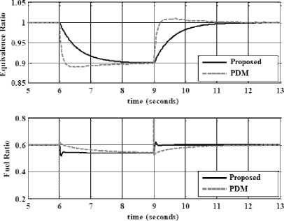
Figure4: Disturbance rejection; fuzzy PD mass of air methodology and PD mass of air method
According to the Figure 4; by comparison with PD plus mass of air method overshoot’s (9.1%), fuzzy PD mass of air method’s overshoot (1%) is more robust. response trajectory with 15% disturbance of relative to the input signal amplitude in proposed method and PDM, proposed method’s rise time (0.48) is lower thanPDM’s (0.66).
-
V. CONCLUSION
This research has studied PD plus mass of air design for the dynamics of IC engine without knowledge of the boundary of the disturbances/uncertainties, using fuzzy PD plus mass of air controls as robust controls for the IC engine and as a solution to the problem of stability and robustness. To elucidate this, aPD plus mass of air control for the IC engine which includes the unknown bounded disturbances and uncertainties is studied. A PD plus mass of air is introduced as a robust control, which provides ultimate accuracy in the presence of the matched bounded disturbances/uncertainties. The result has problems because some parameters are unknown which caused to oscillation; the oscillation may actually damage components and cause loss of accuracy of output. As a solution, model reference fuzzy method is introduced. Fuzzy method mitigates oscillation by model like systems dynamic. To conclude, the fuzzy PD plus mass of air control is demonstrated to be the robust control for the unmodeled system, and an effective algorithm to avoid overestimation of controller gains and to mitigate oscillation by model reference fuzzy method.
ACKNOWLEDGMENT
The authors would like to thank the anonymous reviewers for their careful reading of this paper and for their helpful comments. This work was supported by the SSP Research and Development Corporation Program of Iran under grant no. 2012-Persian Gulf-2B.
References Design Novel Model Reference Artificial Intelligence Based Methodology to Optimized Fuel Ratio in IC Engine
- Heywood, J., “Internal Combustion Engine Fundamentals”, McGraw-Hill, New York, 1988.
- J. G. Rivard, "Closed-loop Electronic Fuel Injection Control of the IC Engine," in Society of Automotive Engineers, 1973.
- J. F. Cassidy, et al, "On the Design of Electronic Automotive Engine Controls using linear Quadratic Control Theory," IEEE Trans on Control Systems, vol. AC-25, October 1980. DOI:10.1109/TAC.1980.1102457
- W. E. Powers, "Applications of Optimal Control and Kalman Filtering to Automotive Systems," International Journal of Vehicle Design, vol. Applications of Control Theory in the Automotive Industry, 1983.
- N. F. Benninger, et al, "Requirements and Perfomance of Engine Management Systems under Transient Conditions," in Society of Automotive Engineers, 1991.
- N. F. Benninger, et al, "Requirements and Perfomance of Engine Management Systems under Transient Conditions," in Society of Automotive Engineers, 1991.
- C. H. Onder, et al, "Model-Based Multivariable Speed and Air-to-Fuel Ratio Control of an SI Engine," in Society of Automotive Engineers, 1993.
- S. B. Cho, et al, "An Observer-based Controller Design Method for Automotive Fuel-Injection Systems," in American Controls Conference, 1993, pp. 2567-2571.
- T. Kume, et al, "Combustion Technologies for Direct Injection SI Engine," in Society of Automotive Engineers, 1996. DOI:http://dx.doi.org/10.1016/S0389-4304(96)80489-9
- V. Utkin, "Variable structure systems with sliding modes," Automatic Control, IEEE Transactions on, No. 2,vol. 22, pp. 212-222, 2002.DOI:10.1109/TAC.1977.1101446
- R. A. DeCarlo, S. H. Zak and G. P. Matthews, "Variable structure control of nonlinear multivariable systems: a tutorial," Proceedings of the IEEE, No. 3,vol. 76, pp. 212-232, 2002.DOI:10.1109/5.4400
- K. D. Young, V. Utkin and U. Ozguner, "A control engineer's guide to sliding mode control," IEEE conference proceeding, 2002, pp. 1-14.DOI:10.1109/VSS.1996.578521
- O. Kaynak, "Guest editorial special section on computationally intelligent methodologies and sliding-mode control," IEEE Transactions on Industrial Electronics, No. 1, vol. 48, pp. 2-3, 2001.
- P. Kachroo and M. Tomizuka, "Chattering reduction and error convergence in the sliding-mode control of a class of nonlinear systems," Automatic Control, IEEE Transactions on, No. 7, vol. 41, pp. 1063-1068, 2002.
- J. Moura and N. Olgac, "A comparative study on simulations vs. experiments of SMCPE," IEEE conference proceeding, 2002, pp. 996-1000.
- Farzin Piltan , N. Sulaiman, Zahra Tajpaykar, Payman Ferdosali, Mehdi Rashidi, “Design Artificial Nonlinear Robust Controller Based on CTLC and FSMC with Tunable Gain,” International Journal of Robotic and Automation, 2 (3): 205-220, 2011.
- Farzin Piltan, A. R. Salehi and Nasri B Sulaiman.,” Design artificial robust control of second order system based on adaptive fuzzy gain scheduling,” world applied science journal (WASJ), 13 (5): 1085-1092, 2011.
- Farzin Piltan, Nasri Sulaiman, M. H. Marhaban and R. Ramli, “Design On-Line Tunable Gain Artificial Nonlinear Controller,” Journal of Advances In Computer Research, 2 (4): 75-83, 2011.
- Farzin Piltan, N. Sulaiman, Payman Ferdosali, Iraj Assadi Talooki, “ Design Model Free Fuzzy Sliding Mode Control: Applied to Internal Combustion Engine,” International Journal of Engineering, 5 (4):302-312, 2011.
- Farzin Piltan, N. Sulaiman, Iraj Asadi Talooki, Payman Ferdosali, “Control of IC Engine: Design a Novel MIMO Fuzzy Backstepping Adaptive Based Fuzzy Estimator Variable Structure Control , International Journal of Robotics and Automation, 2 (5):360-380, 2011.
- Farzin Piltan, N. Sulaiman, Payman Ferdosali, Mehdi Rashidi, Zahra Tajpeikar, “Adaptive MIMO Fuzzy Compensate Fuzzy Sliding Mode Algorithm: Applied to Second Order Nonlinear System,” International Journal of Engineering, 5 (5): 380-398, 2011.
- Farzin Piltan, N. Sulaiman, Hajar Nasiri, Sadeq Allahdadi, Mohammad A. Bairami, “Novel Robot Manipulator Adaptive Artificial Control: Design a Novel SISO Adaptive Fuzzy Sliding Algorithm Inverse Dynamic Like Method,” International Journal of Engineering, 5 (5): 399-418, 2011.
- Farzin Piltan, Reza Bayat, Saleh Mehrara, Javad Meigolinejad“GDO Artificial Intelligence-Based Switching PID Baseline Feedback Linearization Method: Controlled PUMA Workspace,” International Journal of Information Engineering and Electronic Business (IJIEEB), 4 (5):17-26, 2012.
- Farzin Piltan, SH. Tayebi HAGHIGHI, N. Sulaiman, Iman Nazari, Sobhan Siamak, “Artificial Control of PUMA Robot Manipulator: A-Review of Fuzzy Inference Engine And Application to Classical Controller ,” International Journal of Robotics and Automation, 2 (5):401-425, 2011.
- Farzin Piltan, Amin Jalali, N. Sulaiman, Atefeh Gavahian, Sobhan Siamak, “Novel Artificial Control of Nonlinear Uncertain System: Design a Novel Modified PSO SISO Lyapunov Based Fuzzy Sliding Mode Algorithm ,” International Journal of Robotics and Automation, 2 (5): 298-316, 2011.
- Farzin Piltan,N. Sulaiman, S.Soltani, M. H. Marhaban&R. Ramli, “An Adaptive sliding surface slope adjustment in PD Sliding Mode Fuzzy Control for Robot Manipulator,” International Journal of Control and Automation , 4 (3): 65-76, 2011.
- Farzin Piltan, N. Sulaiman, Amin Jalali, Sobhan Siamak, and Iman Nazari, “Control of Robot Manipulator: Design a Novel Tuning MIMO Fuzzy Backstepping Adaptive Based Fuzzy Estimator Variable Structure Control ,” International Journal of Control and Automation, 4 (4):91-110, 2011.
- Farzin Piltan,N. Sulaiman and I.AsadiTalooki, “Evolutionary Design on-line Sliding Fuzzy Gain Scheduling Sliding Mode Algorithm: Applied to Internal Combustion Engine,” International Journal of Engineering Science and Technology, 3 (10):7301-7308, 2011.
- Farzin Piltan, Nasri B Sulaiman, Iraj Asadi Talooki and Payman Ferdosali.,” Designing On-Line Tunable Gain Fuzzy Sliding Mode Controller Using Sliding Mode Fuzzy Algorithm: Applied to Internal Combustion Engine,” world applied science journal (WASJ), 15 (3): 422-428, 2011.
- Farzin Piltan, H. Rezaie, B. Boroomand, Arman Jahed,” Design robust back stepping online tuning feedback linearization control applied to IC engine,”International Journal of Advance Science and Technology, 42: 183-204, 2012.
- Farzin Piltan, Bamdad Boroomand, Arman Jahed, Hossain Rezaie " Performance-Based Adaptive Gradient Descent Optimal Coefficient Fuzzy Sliding Mode Methodology". International Journal of Intelligent Systems and Applications (IJISA), 4 (11), 40-52, 2012.
