Design of a heat exchanger - a heat energy accumulator with an oscillating coil for heating hot water with a capacity of 25 kW

Author: Chen Xuanyou, Golyanin Anton
Journal: Бюллетень науки и практики @bulletennauki
Section: Технические науки
Article in issue: 8 т.8, 2022.
Free access
The subject of the research is designing a regenerative heat exchanger to heat hot water. Qualitative and quantitative analysis of relevant physical parameters to optimize heat exchanger models. The purpose of this study is to simulate realizing the goal of heating hot water with 25 kW and optimize the model to optimize the heat exchange efficiency in practical work. As a result of the research, Amplitude-frequency response of the circuit increases linearly as speed of rotation. When the speed is constant, the less of water mass is, the value of Amplitude great. The phase frequency response of the circuit increases overall as the speed increases. The greater the mass, the greater, and the rate of increase gradually decreases. we know that increasing the water volume can improve the heat transfer efficiency, but when the water volume (G) increases to 1.6, the rate of increasing the heat transfer efficiency begins to decline, so this should be taken into account in the design process. With the heating time increases, the heat transfer efficiency will also improve. It should be noted that when the heating time increases, the rate of increase of heat transfer efficiency decreases and specific heat capacity (KF) decreases.
Accumulator of heat exchanger, general spiral, heart transfer, energy of flow
Short address: https://sciup.org/14124773
IDR: 14124773 | UDC: 621.311.243 | DOI: 10.33619/2414-2948/81/33
Конструкция теплообменника-аккумулятора тепловой энергии с колебательным змеевиком для нагрева горячей воды мощностью 25 кВт
Предметом исследования является проектирование рекуперативного теплообменника для нагрева горячей воды. Проведен качественный и количественный анализ соответствующих физических параметров для оптимизации моделей теплообменников. Целью исследования является моделирование нагрева горячей воды и оптимизация эффективности модели теплообмена мощностью 25 кВт в практической работе. В результате исследования установлено, что амплитудно-частотная характеристика контура линейно возрастает с увеличением скорости вращения. Когда скорость постоянна, чем меньше масса воды, тем больше значение амплитуды. Фазочастотная характеристика схемы увеличивается в целом по мере увеличения скорости. Увеличение объема воды может улучшить эффективность теплопередачи, но, когда объем воды (G) увеличивается до 1,6, скорость увеличения эффективности теплопередачи начинает снижаться, поэтому следует учитывать это в процессе проектирования. С увеличением времени нагрева эффективность теплопередачи также будет улучшаться. Следует отметить, что при увеличении времени нагрева снижается скорость повышения эффективности теплообмена и снижается удельная теплоемкость (КФ).
Text of the scientific article Design of a heat exchanger - a heat energy accumulator with an oscillating coil for heating hot water with a capacity of 25 kW
Бюллетень науки и практики / Bulletin of Science and Practice Т. 8. №8. 2022
UDC 621.311.243
Regenerative heat exchange technology for the rise of the 1980s of the new energy saving technology, the biggest characteristic of this technology is efficient energy saving, the average energy saving rate on the existing basis can be increased by 30% [1]; The significance of the application of regenerative heat exchange technology is that it not only saves fuel to the greatest extent but also reduces pollutant emissions, especially NOx emissions [2].
With the continuous improvement of heat exchange theory and the improvement of steel properties, the heat exchange performance of heat exchange device has made great progress [3]. Due to the wide application of heat exchanger, almost covering all manufacturing and other fields, according to the physical properties of the heat transfer fluid, operating parameters and other characteristics, the structure and type of heat exchanger will produce corresponding changes and adjustments [4]. Due to the influence of thermal physical properties of heat transfer medium, the further improvement of heat recovery rate of current heat exchanger is greatly limited. Regenerative heat exchanger can not only greatly improve the thermal efficiency of equipment, but also get higher heat exchange temperature efficiency [5], so that the fluid after heat exchange can be close to the inlet temperature, which is widely used in high, medium and low temperature thermal equipment. For large-scale energy storage system [6], a large amount of heat storage medium is needed. Due to its low price, such as pebbles, the packed bed heat exchanger can effectively reduce the investment cost [7], land it has more advantages under the condition of high temperature heat storage without gasification and has good applicability in the utilization of low temperature waste heat, industrial waste heat and solar energy heat storage and other fields. Chao-xiang li’s [8] design for the regenerative heat exchanger is put forward based on the mixed diffusion model, the temperature in the heat exchanger frontier extension, on the basis of analysis and in thermal efficiency, guarantee for the highest thermal efficiency of heat exchanger under the constraint condition of structure parameters is designed, studied the theory of regenerative heat exchanger, but not on the design and calculation of periodic heat exchanger. Du et al [9] designed a new type of regenerative tube and shell heat exchanger, used paraffin as phase change materials. For heat transfer fluid velocity, phase change materials and the key factors including phase-change layer thickness to thermal system [3], heatexchange unit/heat storage process is simulated, studied the design of the regenerative heat exchanger. Theory and the solid filling principle is not the same.
The purpose of this study is to simulate realizing the goal of heating hot water with 25 kW and optimize the model to optimize the heat exchange efficiency in practical work.
Technological scheme of a hot water heater based on a heat exchanger-accumulator with a vibrating coil, with a capacity of 25kW
When the centrifugal pump 7 is turned on, it will supply the coolant to the hot water boiler 1 through the return pipeline 9. In the hot water boiler 1, the coolant will be heated and through the supply pipeline 8 it will be supplied to heat exchanger-accumulator 2, In the heat exchanger- accumulator 2, the heat from the heated coolant will be transformed to cold water. When the set speed is reached, the value of the impact valve quickly close with the formation of a hydraulic shock. In this case, the wave of hydraulic shock is transmitted to the coil 3 and it will oscillate. At the end of the water hummer wave, the valve 6 will open again under the action of spring 10, Thus, the shock valve 6 will periodically close and open, and the coil 3 will oscillate. The vibrations of the coil 3 will increase the heat transfer.
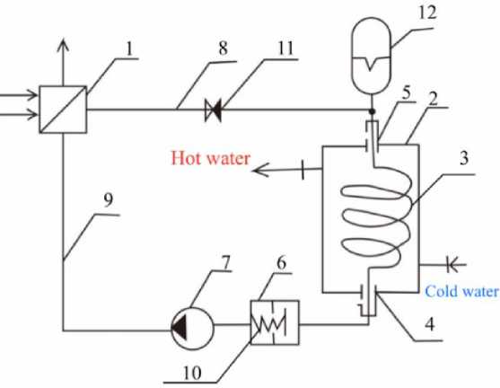
Figure 1. The principle of operation of the scheme: 1 — hot water boiler; 2 — heat exchangeraccumulator; 3 — coil; 4, 5 — movable support; 6 — shock valve; 7 — centrifugal pump; 8 — supply pipeline; 9 — return pipeline; 10 — spring; 11 — check valve; 12 — hydraulic accumulator
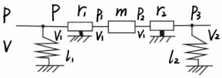
Hydraulic circuit
The hydraulic circuit considers the elastic properties of the shock valve 6. the compliance l 1 the active resistance of the coupling from r 1 and r 2 the mass of water in the circuit.
-
Figure 2. The hydraulic circuit
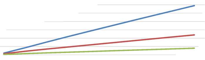
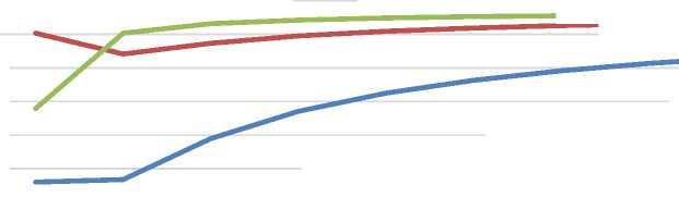
After obtaining certain parameters, the graphical dependences of the obtained dependences of the frequency characteristics and the technical result of this installation scheme are made, the data are presented in Figures 3 and 4.
As Figure 3-4 shown, Amplitude — frequency response of the circuit increases linearly as speed of rotation. When the speed is constant, the less of water mass is, the value of Amplitude great. The phase frequency response of the circuit increases overall as the speed increases. The greater the mass, the greater, and the rate of increase gradually decreases.
A(jΩ) 0,7 0,6 0,5 0,4 0,3 0,2 0,1 0,0
1 2 3 4 5 6 7 8 9 10
^^^м m=40 ^^^мm=100 ^^^мm=300
-
Figure 3. Amplitude-frequency response
φ(jΩ)
1,6
1,5
1,4
1,3
1,2
1,1
1,0
1 2 3 4 5 6 7 8 9 10
Ω
«м^нм» m=40 ^^^^^мm=100 m=300
Figure 4. Phase-frequency function of the energy circuit
Results of heat exchange calculation.
In this section, we present the result of heat exchanger calculation. Table shows the main parameters of calculating the heat exchanger, and they were identified as a result of mathematical modeling.
Table
THE MAIN PARAMETERS OF THE HEAT EXCHANGE
Water volume М initial temperature t2'
500 kg
final temperature t2''
Heating water consumption G1
5 ℃
70 ℃ 0,8 kg/с
the initial temperature of the heating water t1'
80 ℃
Heating time τ
outer diameter of the coil d2
inner diameter of the coil d1 water heat capacityс1
5 h
25 mm
21 mm
4,189 kJ/kg*C
Kinematic viscosity
0,0000005 sq. m/s
Observe the physical parameters of the heat exchanger as they change by changing some data in Table 1, such as the volume of water G and the heating time T, we can see some patterns in Figure 5-8. KF— specific heating capacity; α2 — heat transfer coefficient; F — heat exchange surface; n — the number of coils; L — the length of the coil.
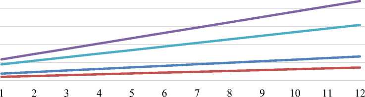
Figure 5. Variation of water volume G and some physical parameters
«■■■■ж F
^^^^^м KF
-
■■■■■■■■I n
L
G
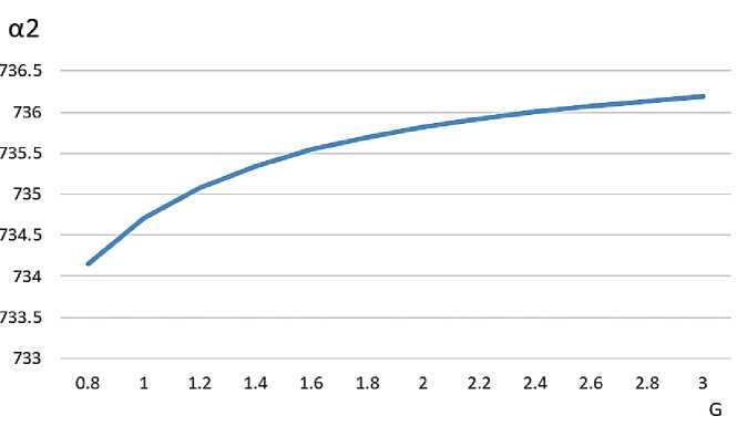
Figure 6. Variation of water volume G and α2
As Figure 5–6 shown, KF, F, n, and L increases linearly as water volume G increases; Increasing the water volume can improve the heat transfer efficiency, but when the water volume (G) increases to 1.6, the rate of increasing the heat transfer efficiency begins to decline, so this should be taken into account in the design process. At the same time, the heat transfer area of the heat exchanger needs more
7,00
6,00
5,00
4,00
3,00 ^^^м KF
2,00 ^^^м F
1,00
0,00
5 5,5 6 6,5 7 7,5 8 8,5 9 9,5 10 10,5 T
-
Figure 7. Variation of heating time T and some physical parameters
As Figure 7–8 shown, with the heating time increases, the heat transfer efficiency will also improve. It should be noted that when the heating time increases, the rate of increase of heat transfer efficiency decreases and specific heat capacity (KF) decreases. F and L increases with increasing heating time, but the overall increase is not very significant. When heating time increase, the number of coils is a constant. The heating time should be well controlled in the design to achieve better heat transfer performance.
α2 736
735,5
734,5
733,5

5 5,5 6 6,5 7 7,5 8 8,5 9 9,5 10 10,5
T
Figure 8 Variation of heating time T and α2
Conclusion
Amplitude — frequency response of the circuit increases linearly as speed of rotation. When the speed is constant, the less of water mass is, the value of Amplitude bigger. The phase frequency response of the circuit increases overall as the speed increases. The greater the mass, the greater, and the rate of increase gradually decreases.
Increasing the water volume can improve the heat transfer efficiency, but when the water volume (G) increases to 1.6, the rate of increasing the heat transfer efficiency begins to decline, so this should be taken into account in the design process. At the same time, the heat transfer area of the heat exchanger needs more.
With the heating time increases, the heat transfer efficiency will also improve. It should be noted that when the heating time increases, the rate of increase of heat transfer efficiency decreases and specific heat capacity (KF) decreases. The heating time should be well controlled in the design to achieve better heat transfer performance. When heating time increase, the number of coils is a constant.
In addition, increasing the heating time does not change the number of coils, but length of the coils requires higher.
References Design of a heat exchanger - a heat energy accumulator with an oscillating coil for heating hot water with a capacity of 25 kW
- Amagour M. E. H., Rachek A., Bennajah M., Touhami M. E. Experimental investigation and comparative performance analysis of a compact finned-tube heat exchanger uniformly filled with a phase change material for thermal energy storage // Energy conversion and management. 2018. V. 165. P. 137-151.
- Agyenim F., Hewitt N., Eames P., Smyth M. A review of materials, heat transfer and phase change problem formulation for latent heat thermal energy storage systems (LHTESS) // Renewable and sustainable energy reviews. 2010. V. 14. №2. P. 615-628.
- Hasnain S. M. Review on sustainable thermal energy storage technologies, Part I: heat storage materials and techniques // Energy conversion and management. 1998. V. 39. №11. P. 1127-1138.
- Constantin L., Dragomir-Stanciu D., Crismaru I. V. Optimization of heat exchange in a heat accumulator with latent heat storage // Procedia Technology. 2015. V. 19. P. 737-741.
- Navarro-Esbri J., Cabello R., Torrella E. Experimental evaluation of the internal heat exchanger influence on a vapour compression plant Energy efficiency working with R22, R134a and R407C // Energy. 2005. V. 30. №5. P. 621-636.
- Aydin D., Casey S. P., Riffat S. The latest advancements on thermochemical heat storage systems // Renewable and Sustainable Energy Reviews. 2015. V. 41. P. 356-367.
- Nazir H., Batool M., Osorio F. J. B., Isaza-Ruiz M., Xu X., Vignarooban K., Kannan A. M. Recent developments in phase change materials for energy storage applications: A review // International Journal of Heat and Mass Transfer. 2019. V. 129. P. 491-523.
- Bellocchi S., Guizzi G. L., Manno M., Salvatori M., Zaccagnini A. Reversible heat pump HVAC system with regenerative heat exchanger for electric vehicles: Analysis of its impact on driving range // Applied Thermal Engineering. 2018. V. 129. P. 290-305.
- Xiao X., Zhang P. Numerical and experimental study of heat transfer characteristics of a shell-tube latent heat storage system: Part I-Charging process // Energy. 2015. V. 79. P. 337-350.
