Design of dangerous driving behavior detection system based on STM32

Author: Cheng Changshan, Levtsev Aleksei, Zhao Changhao, Song Mengchen, Min Xubo
Journal: Бюллетень науки и практики @bulletennauki
Section: Технические науки
Article in issue: 8 т.8, 2022.
Free access
With the rapid development of China’s economy and the continuous improvement of the living standards of the people, cars have gradually become an indispensable tool for travel. At the same time as the number of cars increases rapidly, the accident rate of road traffic is also increasing. Traffic accidents caused by dangerous driving behavior account for a large part of the accident rate. In order to reduce the road traffic accident rate, a vehicle dangerous driving behavior detection system using STM32 single-chip microcomputer is designed from the vehicle itself, which mainly detects the speed and weight of the vehicle. When the vehicle is in the starting state, the detection system detects the weight and speed of the vehicle in real time through the sensor and the motor speed. In this system, the STM32 is used as a core MCU. When the speed or weight of the vehicle exceeds the threshold, the MCU performs an alarm and subsequent operations. This design introduces the overall design of the system in detail, from the test of each module to the use of the overall connection test, the interface module and STM32 interface circuit as well as the system hardware circuit and related peripheral circuits are given, and finally the measurement data is displayed through the OLED. The design is simple in structure and can be applied to various vehicles.
Stm32 single chip microcomputer, pressure sensor, hall sensor
Short address: https://sciup.org/14125295
IDR: 14125295 | UDC: 656.071.32.072 | DOI: 10.33619/2414-2948/81/27
Разработка системы на базе STM32 для обнаружения опасного поведения водителя
С быстрым развитием экономики Китая и постоянным повышением уровня жизни в стране автомобили постепенно становятся необходимым средством передвижения. Стремительный рост числа автомобилей сопровождался постоянным увеличением количества дорожно-транспортных происшествий. Дорожно-транспортные происшествия, вызванные опасным поведением водителей (например, превышение скорости, перегрузка и т. д.), составляют немалую часть от общего числа ДТП. Для того чтобы снизить уровень дорожно-транспортных происшествий, система обнаружения опасного поведения водителя транспортного средства с использованием микроконтроллера STM32 разработана на основе самого автомобиля, который в основном определяет скорость и вес транспортного средства. Эта система обнаружения определяет вес и скорость автомобиля в реальном времени с помощью датчиков, а также скорость двигателя, когда автомобиль находится в состоянии запуска. В этой системе в качестве основного микроконтроллера используется STM32, и когда скорость или вес автомобиля превышают пороговое значение, микроконтроллер выполняет сигнал тревоги и последующие операции. В этом проекте подробно описывается общая конструкция системы, от тестирования отдельных модулей до общего шарнирного тестового использования, приводятся схемы интерфейсного модуля и STM32, а также схемы аппаратного обеспечения системы, связанные периферийные схемы и т. д. Данные измерений в конечном итоге отображаются на OLED ЖК-дисплее. Конструкция проста по строению и может применяться на всех типах транспортных средств.
Text of the scientific article Design of dangerous driving behavior detection system based on STM32
Бюллетень науки и практики / Bulletin of Science and Practice Т. 8. №8. 2022
UDC 656.071.32.072
With the continuous improvement of China's national economy, the per capita car ownership in China is also rising. According to statistics from the 2018 China National Economic and Social Development Statistical Bulletin, China's national car ownership at the end of 2018 was 240.28 million (including 9.06 million three-wheeled vehicles and low-speed freight vehicles), an increase of 10.5% over the end of 2017, including 207.3 million private cars, an increase of 10.9% year-on-year. The number of civilian cars is 134.51 million, an increase of 10.4%, including 125.89 million private cars, an increase of 10.3%. This design simulates the detection of dangerous driving system part - load detection and speed detection. The STM32 microcontroller is used to control the model part of the intelligent car, which is used to realize the detection and alarm functions.
Now the market sales of car safety driving alarm system mainly for electronic dog, single frequency or triple frequency speed radar alarm, GPS speed radar alarm, etc.. Through the survey can be found on the market most of the alarms are mostly to avoid the traffic police department speed detection system, and can not improve traffic safety, but will encourage some drivers to get lucky. And most freight vehicles are basically no weight detection system, which leads to freight drivers will occasionally overload transport, thus occurring danger when the brake is too late or due to the braking distance is too long and lead to traffic accidents.
This design is mainly based on STM32 microcontroller and DC motor equipped with Hall encoder and pressure sensor. The STM32 microcontroller is used as the core to control the operation of the whole system. The STM32 microcontroller is controlled so that the speed and weight can be controlled and detected. This design focuses on the hardware circuit design by partial physical as well as experimental. The details are as follows.
-
(1) The STM32 microcontroller is used as the core control, by controlling the STM32 microcontroller and then controlling the function of each other module to achieve.
-
(2) Test the pressure sensor module and the motor drive speed module separately to check whether they can accomplish their intended goals and to perform basic debugging of them.
-
(3) Soldering the hardware circuit, supplying power to the motor, and testing the speed so that it can perform basic operation.
-
(4) Assemble each module part as a whole to carry a complete circuit and design.
-
(5) Debug the piggybacked system as a whole to improve the problematic parts and finally achieve the desired goal.
The main purpose of this design is that this system device is mainly used to remind drivers to drive safely, obey traffic rules, and prevent traffic accidents due to dangerous driving. The dangerous driving behavior detection system is an experiment with practical value, and circuit welding, motor regulation and program modification, etc. will be used in the design process.
Hazardous driving system design circuit mainly consists of power supply module, STM32 microcontroller system module, motor drive speed measurement module and pressure sensor module.
The STM32 microcontroller as the core of the control system, using the composition of multiple modules, external pressure sensors and motor-driven speed module to achieve the purpose of detecting weight and speed. And the parameters detected by the module return to the microcontroller for processing, and then through the microcontroller for data transmission.
The STM32-based hazardous driving system detection is powered by a power supply module to the microcontroller, which enables the microcontroller to control each module to achieve the desired goal. The reset module performs the reset and initialization of the system, the crystal circuit provides the clock signal to the microcontroller to ensure the normal operation of the system, the motor drive speed module supplies power to the motor to ensure normal operation and speed measurement function, and the pressure sensor measures the load weight. The block diagram of the system structure is drawn according to the designed functions, as shown in Figure 1.
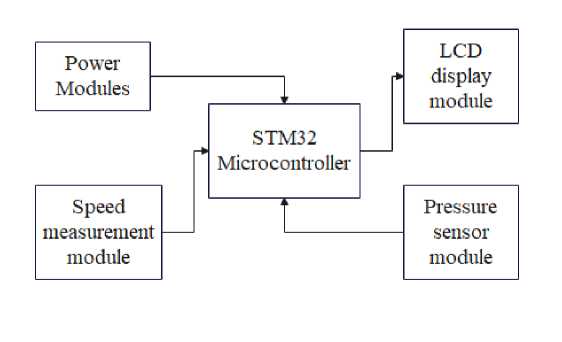
Figure 1. Overall system block diagram
The hardware of this design of dangerous driving detection system design has the following main components.
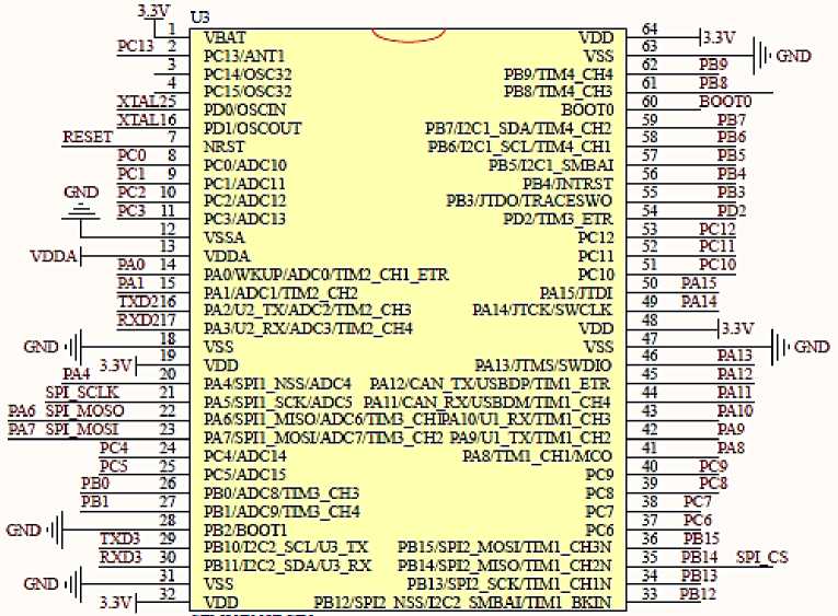
The main control module adopts STM32 microcontroller as the core control board, which also contains reset circuit, etc. STM32 microcontroller is used to control motor drive speed measurement module, pressure sensor module and OLED display module. The reset circuit adopts manual reset to ensure normal operation after manual reset in case the microcontroller does not work properly. As shown in Figure 2.
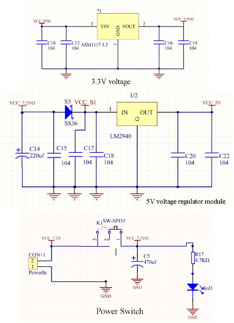
Figure 2. STM32 microcontroller schematic
The design is mainly powered by a 7.2V lithium battery. the STM32 microcontroller can be powered by a J-link downloader or by 3.3V. The regulated 5V voltage source is used to power the pins of the pressure sensor module and the driver module part as well as the encoder. The drive motor voltage range is 6.5V15V, so the 7.2V power supply can be directly connected to the driver module pins to ensure normal use. This is shown in Figure 3.
PC4
ЙАв ЗИ MOSO 22
£47 ЗИ MOST 23
44 РАН vdda|-
GND 1
РА4 ЗЛ^
РАО 14
Й41 15
TXD216
RXD217
РСО S
РС1 9
GKD РС2 10
-3=- РСЗ 11
РВ1
ел)'
GND ■
TXD3 29
RXD3 30
________ 31
33V^
MV pbHI1'®® PBS
43 РАЮ
42 РА9
41 PAS
3S PC7
37 PCS
36 PB15
35 PB14 SPI CS
34 ___PB13
33 PB12
XIAL25
XLAL16
RESET 7
PC5 25
PBO 26
40 ____PC9
39 PCS
BOOTO
__PB7
PBS
PB5
PB4
PB3
PD2
PC12
PC11
РСЮ
|l'G®
PA15
PA14
PA13
PA12
3.3V
PC13 2
TOD
PBH'SPD
PC4.'ADC14
PC5/ADC15
PB1 ADC9HXB_CH4
PB2BOOT1
РВНИ2С2 SCIAB IX
PB1 L'EC2_SDA'U3_RX
VSS
PC7 PCS
PB15.SH2_MOSLTIM1_CH3N
PB14.SH2_MISQTIM1_CH2N
PB137SM2SCK/IIM1_CH1N
NSS.EC2 SMBATHM1 BHN
PD2/TIM3 ETR
PC12 PC11 PC10
TOD
VSS
PABmiSSWDIO
PAO'WKUP/ADCaTIM2 CHI ETR
PAL'ADC1.TIM2_CH2
P.A2'U2_TX'ADC2TI№_CH3
PA3,w'RXZADC37nM2_CH4
VSS
TOD
VBAT
PC13/ANT1
PC14OSC32
PC15OSC32 PDOOSCIN
PD10SCOLT NRST
PCO'ADCIO
PCI ADC11
PC2/ADC12
PC3..'ADC13
VS SA TODA
РА8ИМ1_СНШСО
PCT
TOD
VSS
РВ9Л1М4 CH4
PBSHM4_CH3
BOOTO
P37,I2C1_SDATD.I4_CH2
РВ6Л2С1 8С1Л1М4 CHI
PB5I2C1_SMBAI
PB3 JIDOTRACESWO
Figure 3. Power supply module circuit schematic
The design adopts a dual motor drive method to drive the encoder motor through the motor drive module composed of TB6612FNG chip, and speed and steering control can be achieved by changing the polarity and voltage. As shown in Figure 4.
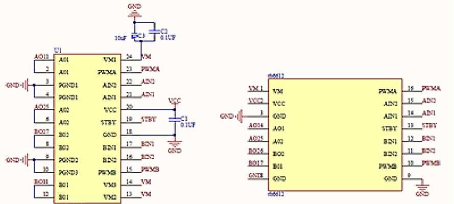
Figure 4. Motor drive module composed of TB6612FNG
Бюллетень науки и практики / Bulletin of Science and Practice Т. 8. №8. 2022
To achieve the above functions, a 7.2V power supply can be used for direct power supply, but the load capacity of the microcontroller IO port is weak, and the DC motor is a high-current inductive load, so a motor driver module consisting of the TB6612 chip is used.
Among them, TB6112FNG is a DC motor driver chip produced by Toshiba, the largest semiconductor manufacturing company in Japan, which has the characteristics of dual-channel circuit output, high-current MOSFET-H-bridge structure, and can drive two motors simultaneously.
The Hall encoder is a sensor that converts the geometric displacement on the output axis into a pulse signal or digital quantity through magneto-electric conversion. The encoder consists of a Hall code plate and a Hall element. The Hall code plate is a circular plate of a certain diameter with different magnetic poles arranged in equal parts. When the motor rotates, the Hall element detects and outputs a number of pulses. Generally, two sets of square wave signals with a certain phase difference are output, and the STM32 microcontroller comes with an encoder interface, so it can be directly connected to the microcontroller IO port.
Since this design is still quite different from the specific vehicle, the module integrated with the HX711 chip is used as the analog weight measurement module. Compared with other chips of the same type, this chip has integrated internal voltage regulator and on-chip clock oscillator, etc., while other chips of the same type need similar peripheral circuits. The chip has the advantages of high integration, fast response time, and relatively strong anti-interference performance. At the same time, the interface and programming of this chip with STM32 microcontroller is relatively simple compared with other chips of the same type, and all control signals can be driven by the pins without the need to process and program the registers inside the chip. As shown in Figure 5.
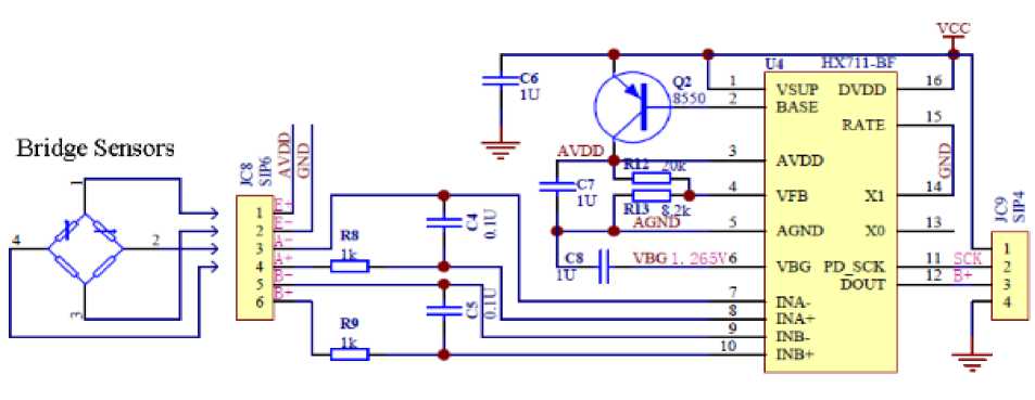
Figure 5. Pressure sensor module
After final selection and debugging, a 0.96" OLED was chosen to display the measured pressure values. The display can support IIC or SPI input mode, and through practice the OLED uses the SPI input mode. Where SDA is the data line, SCL is the clock line, RES is the display reset pin, DC is the data/command selection pin, CS is the data chip selection, low level active, when not in use need to ground cannot be suspended. Finally, the measured pressure value is displayed through the OLED. As shown in Figure 6.
VCC 3.3V2
|
GND 1 |
U7 |
|
|
2 |
GND VCC SCL SDA RES DC CS |
|
|
I2C |
SCL 3 |
|
|
I2C SDA 4 |
||
|
AO 5 |
||
|
B9 6 |
||
|
B8 7 |
||
OLED 0.96
Figure 6. OLED display module
First, each module, including the whole system, is initialized and then enters the main program loop. The system automatically detects the speed and pressure values and displays them on the OLED screen, and compares the detected values with the preset values to find out whether the vehicle is overloaded. If there is overload, the OLED display will show an error; if there is no overload, the system will work normally. As shown in Figure 7.
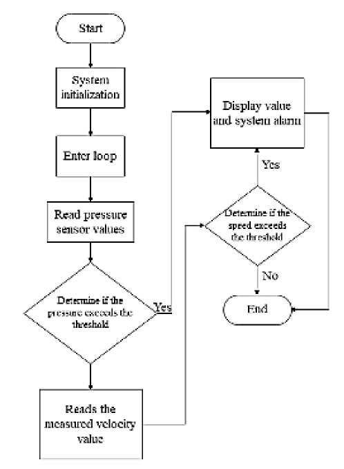
Figure 7. General block diagram of the system program
The main function program first performs the initialization of the motor drive speed measurement module, pressure sensor module, and OLED display module, and then enters the big loop program.
In the big loop program, it first enters the value acquisition of the pressure sensor, gets a reading value, and then compares with the preset value. If the value exceeds the preset value, it will directly alarm and jump out of the cycle without executing the subsequent operations. If it is within the preset value, then the speed measurement module reads the value and compares it with the preset value. If the speed does not exceed the preset value, the system operates normally; if it exceeds the preset value, the alarm is raised and the cycle is jumped. As shown in Figure 8.
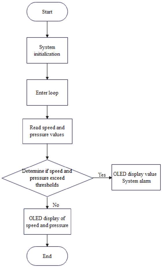
Figure 8. Main program flow block diagram
Because the encoder output is a standard square wave and the STM32 microcontroller comes with an encoder interface, it can be directly wired using the hardware technique, i.e., the IO port is directly wired. Connect to the STM32 microcontroller IO port for direct reading. As shown in Figure 9.
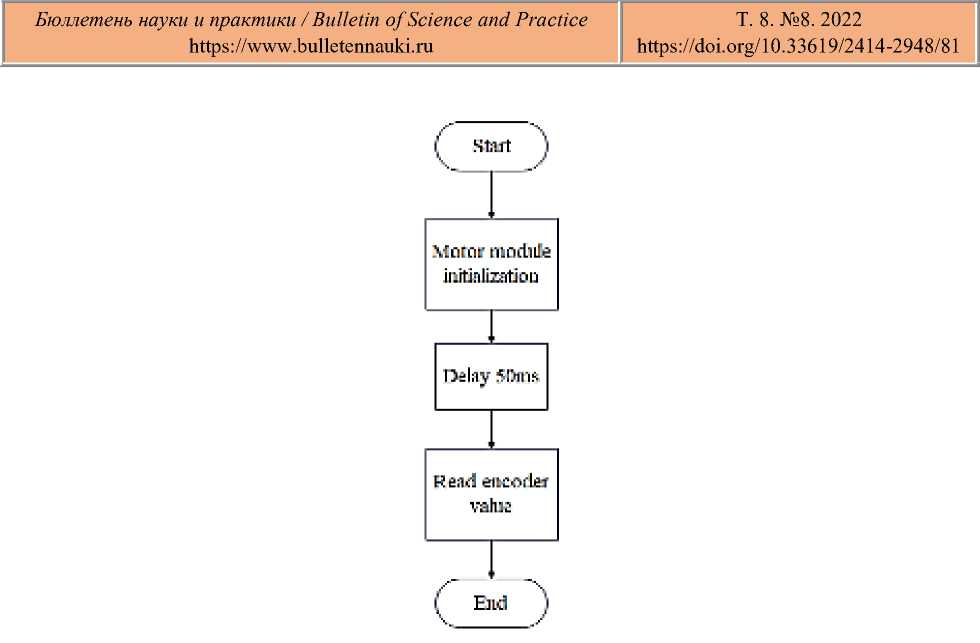
Figure 9. Block diagram of motor speed reading process
The pressure sensor module integrated by the HX711 chip is relatively easy to interface and program with the STM32 microcontroller at the back end. All control signals can be driven by the STM32 microcontroller pins without programming the registers inside the chip. The clock oscillator inside the chip does not require any external devices. As shown in Figure 10.

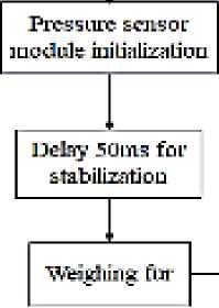
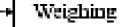
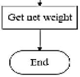
Figure 10. Pressure sensor module data reading program flow block diagram
The OLED mainly displays the measured weight value and detects in real time whether the predetermined value is exceeded or not, and displays an error if the predetermined value is exceeded. As shown in Figure 11.
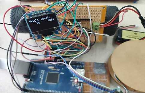
Figure 11. OLED module program flow block diagram
This time, we mainly use keil5 to test each module and debug the system in general. The main task of software debugging is to debug through the physical circuit, find and modify the errors in the program, and find faults in the physical operation results. In the process of debugging the program, we should first design independent debugging subroutine modules to test whether the program can achieve the expected functions and whether the interface control circuit is normal, and finally gradually connect the subroutines for total debugging.
After the program debugging and software simulation, the program written can run normally and meet the requirements, the system can achieve the expected results of operation. Later on, the welding of some physical parts is carried out. According to the corresponding circuit schematic, the required components are laid out and welded on the circuit board in a reasonable manner. After the welding is completed, the hardware is debugged. The system power supply OLED initialization after the boot interface is shown in Figure 12.
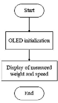
Figure 12. OLED interface after power-on initialization
A cell phone is placed on the module to simulate the normal load, at this time the motor power supply starts to rotate normally. As shown in Figure 13.
Increase the load mass until it exceeds the warning value to show the error, as shown in Figure 14.
The motor measures the speed as shown in Figure 15.
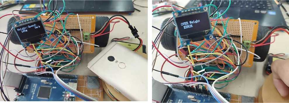
Figure 13. Simulated load test weight graph
Figure 14. Load weight exceeding the maximum value display error
|
^ speed_ml ^ speed_mr 0 PWM |
6 |
int |
|
7 |
int |
|
|
0 |
float |
|
|
..... V speed |
6.66149712 |
float |
Figure 15. Motor test speed
Where speed_ml is the left wheel speed and speed_mr is the right wheel speed. Where speed is the total speed, which is the number of pulses output from the encoder in one second. The calculation formula is V= (the number of pulses output from the encoder in one second/1600) *60 m/s.
Through a series of debugging, the above series of result graphs were finally obtained. Basically, the desired design purpose is accomplished.
During the process of this design, I encountered a lot of difficulties, and even though I had some experience as well as basic knowledge, I kept encountering new problems in the process of practical operation.
The selection of materials for speed detection has photoelectric type as well as encoder type, etc., and finally choose the motor with Hall sensor encoder. The motor can better achieve the control role, while Hall sensor speed measurement is relatively convenient and cost-effective. For the selection of pressure sensors, it is not possible to achieve a large load test and therefore take the analog way. Therefore, the HX711AD chip, which is also cost-effective, was finally used.
Next, the pressure sensor module is relatively easy to test because of its simple procedure. However, the complexity of the motor speed measurement led to slow progress.
Finally, we soldered the circuit boards, built the complete system, and started debugging the whole system until we reached the expected goal. After a period of hard work, the STM32-based dangerous driving behavior detection system is basically complete. In the process, many new control methods were learned, new chip programming was learned, and the chips were soldered.
References Design of dangerous driving behavior detection system based on STM32
- Statistical Bulletin of the People's Republic of China on National Economic and Social Development in 2018.
- Li, Shuo (2015). Research and system construction of dangerous driving state detection mechanism. Nanjing: Master's thesis for professional degree of Nanjing University of Posts and Telecommunications.
- Lu, Sen-Xing (2015). Sensor strategy in the construction of detection system. China Science and Technology Information, (11), 95-97.
- Xu, Hui (2015). Video-based vehicle speed detection and speeding alarm system. Inner Mongolia: Master's thesis, Inner Mongolia University of Technology.
- Wang, Hui (2013).Video-based vehicle abnormal behavior detection. Shenyang: Master's thesis, Shenyang University of Technology.
- Wang, Qianjin, & Zheng, Zhanjie (2018). Research and design of computer vision-based dangerous driving early warning system. Journal of Changsha University, 32(05), 37-40.
- Bie, Y., Li, M., & Chen, F. (2017). Heat loss properties of cavity absorber in solar collecting system with parabolic trough concentrator. Acta energiae solaris sinica, 38(2), 423-430.
- Tang, Keshuang,Tal, Chaopeng, & Zhou, Nan (2018). Empirical analysis of dangerous driving behavior during phase switching at intersections based on trajectory data. Chinese Journal of Highways, 31(04), 88-97.
- Zhan, T, Cai, Z. S.,Zhang, J., & Yang, Y. (2011). A dangerous driving behavior detection system based on multi-sensor information fusion. Research and Development, (07), 54-57.
- Jouybari, H. J., Saedodin, S., Zamzamian, A., & Nimvari, M. E. (2017). Experimental investigation of thermal performance and entropy generation of a flat-plate solar collector filled with porous media. Applied Thermal Engineering, 127, 1506-1517. https://doi.org/10.10167j.applthermaleng.2017.08.170
- Wang, Fei, Qi, Peng, & Lu, Shuaihua (2016). Design and application of automatic speeding detection system for motor vehicles. Science and technology innovation and application, (16), 51.
- Chen, C. J. (2013). Integrated design and implementation of large vehicles dangerous driving behavior monitoring system. Wuhan: Wuhan University of Technology Dissertation.
- Chen, Jie (2014). Analysis of factors affecting the thermal performance of flat-panel solar collectors. Chinese Journal of Agricultural Machinery, 35(06), 226-229.
- Guo Tianxiang. New concept 51 microcontroller C language tutorial [M]. Beijing: Electronic Industry Press, 2009.
