Design of Fast Fourier Transform Architecture for GF(24) with Reduced Operational Complexity
 with Reduced Operational Complexity")
Author: Tejaswini P. Deshmukh, Pooja R. Pawar, P. R. Deshmukh, P. K. Dakhole
Journal: International Journal of Image, Graphics and Signal Processing(IJIGSP) @ijigsp
Article in issue: 10 vol.8, 2016.
Free access
In this paper, the architecture for Fast Fourier Transform over Galois Field (24) is described. The method used is cyclotomic decomposition. The Cyclotomic Fast Fourier Transforms (CFFTs) are preferred due to low multiplicative complexity. The approach used is the decomposition of the arbitrary polynomial into a sum of linearized polynomials. Also, Common Subexpression Elimination (CSE) algorithm is used to reduce the additive complexity of the architecture. By using CSE algorithm, the design with reduced operational complexity has been described.
Cyclotomic, Fourier Transform, Galois Field
Short address: https://sciup.org/15014024
IDR: 15014024
Text of the scientific article Design of Fast Fourier Transform Architecture for GF(24) with Reduced Operational Complexity
Published Online October 2016 in MECS
Fourier analysis is useful in converting a signal from its original domain into frequency domain and vice versa. The Fast Fourier Transform (FFT) algorithm designed for the complex field is not well-suited for the finite field. The FFT in the complex field has applications throughout the subject of signal processing [3]. Whereas, the FFT over the finite field have been widely used in cryptography and have applications in error correcting codes. The method for Fast Fourier Transform over the finite field (i.e. Galois Field) [2] [3] along with the architecture has been suggested in the paper. Galois Field is a field that contains a number of finite elements.
The suggested method consists of decomposing an original polynomial into a sum of linearized polynomials and evaluating them at a set of basis points [2]. The architecture designed in this paper is for GF(24). The Cyclotomic Fast Fourier Transform (CFFT) is useful in RS i.e. Reed-Solomon decoders to reduce the complexity of the decoder [4]. Because Reed Solomon code is cyclic in nature [15]. The CFFT proposed in [2] has low multiplicative complexity but they have high additive complexities. The FFT suggested in this paper can be used to perform the RS decoding which involves two time-consuming steps (Syndrome computation and Chien search). Chien search is a fast algorithm used in determining roots of polynomials defined over a finite field. The RS codes are capable of correcting random errors and multiple burst errors. This architecture can also be used to implement the Gao algorithm [14] which includes operations based on Fourier transform.
The design of architecture follows several steps which have been explained in a simplified manner in this paper. The architecture is designed in 4 stages. The architecture so designed is modified by applying Common
Subexpression Elimination (CSE) Algorithm. CSE algorithm reduces the additive complexity of the architecture. The language used for design is Verilog and has been implemented in the Xilinx ISE Design Suite.
The paper proceeds as follows. Section II covers basic notions and definitions of the Fourier transform and the method to determine cyclotomic cosets, along with the basic theory of Galois Field. Section III focuses on linearized polynomials and generation of the matrix. Section IV describes hardware architecture. The Common Sub-expression elimination Algorithm has been explained in section V. Section VI illustrates the architecture after applying CSE. And the paper concludes with the comparison between two architectures in section VII.
-
II. Definitions
-
2.2. The elements can be estimated through:
-
2.3. The cyclotomic cosets Ck over modulo n=2m – 1 for GF(2m) is calculated as:
The Fourier transform of a polynomial is the collection of elements.
The Fourier transform can be generated using [2] [10]:
f to = L^fto (1)
is of degree f(x) = n-1 and n | (2m-1).
f^') X. и 'li (2)
Here, j Є |0, n-1|.
C 0 = {0} ,
C k1 = { k 1 , k 1 2, k 1 22, ....., k 1 2m 1 -1},
...........,
Ckl = { kl , kl 2, kl 22, ....., kl 2ml-1}, where ks ≡ ks2msmodn.(3)
-
2.4. A linearized polynomial over GF(2m) is a polynomial represented as:
Lto = X kx21(4)
It can be shown that L(x) satisfies L(a+b) = L(a) + L(b).
One useful representation of elements in Galois Field is m-tuple representation. Let α0 + α1α + α2α +....+α
αm-1 be the polynomial representation of a field element β. Then, β can be represented by an ordered sequence of m components called an m-tuple, as follows [7]: (α 0 , α 1 , α 2 , . . . , α m-1 )
Where, the m components are simply the m coefficients of the polynomial representation of β.
For GF(24) the 4-tuple representation generated by p(X) = X4+X+1 is:
Table 1. 4-Tuple representation
|
Power representation |
Polynomial representation |
4-Tuple representation |
|
0 |
0 |
(0 0 0 0) |
|
1 |
1 |
(0 0 0 1) |
|
α |
α |
(0 0 1 0) |
|
α2 |
α2 |
(0 1 0 0) |
|
α3 |
α3 |
(1 0 0 0) |
|
α4 |
α+1 |
(0 0 1 1) |
|
α5 |
α2+ α |
(0 1 1 0) |
|
α6 |
α3+ α2 |
(1 1 0 0) |
|
α7 |
α3+α+1 |
(1 0 1 1) |
|
α8 |
α2+1 |
(0 1 0 1) |
|
α9 |
α3+α |
(1 0 1 0) |
|
α10 |
α2+α+1 |
(0 1 1 1) |
|
α11 |
α3+α2+α |
(1 1 1 0) |
|
α12 |
α3+α2+α+1 |
(1 1 1 1) |
|
α13 |
α3+α2+1 |
(1 1 0 1) |
|
α14 |
α3+1 |
(1 0 0 1) |
The elements of GF(2m) forms all the roots of X2^m + X. Let Ø(X) be the polynomial of the smallest degree over GF(2m). This polynomial Ø(X) is called the minimal polynomial of β. Ø(X) must be irreducible. Minimal polynomials of the elements in GF(24) generated by p(X) = X4+X+1 are:
Table 2. Minimal polynomials
|
Conjugate roots |
Minimal polynomials |
|
0 |
X |
|
1 |
X+1 |
|
α, α2, α4, α8 |
X4+X+1 |
|
α3, α6, α9, α12 |
X4+X3+X2+X+1 |
|
α5, α10 |
X2+X+1 |
|
α7, α11, α13, α14 |
X4+X3+1 |
-
III. Cyclotomic Fast Fourier Transform
Based on the formula mentioned in (3) in section II, the cyclotomic cosets so formed for GF(24) after substituting m=4 i.e. n=15 are as follows:
C 0 = {0}
C 1 = C 2 = C 4 = C 8 = {1,2,4,8}
C 3 = C 6 = C 9 = C 12 = {3,6,9,12}
C 5 = C 10 = {5,10}
C 7 = C 11 = C 13 = C 14 = {7,11,13,14}
An irreducible polynomial p(X) of degree m is said to be primitive if the smallest positive integer n for which p(X) divides Xn+1 is n = 2m-1. p(X) = X4+X+1 divides X15+1 but does not divide any Xn+1 for 1 ≤ n ≤ 15. Hence, X4+X+1 is a primitive polynomial for GF(24). Let α be the root of this polynomial.
f(a') can be developed using:
№) = X = Qa («jkl)) (5)
These coefficients α ijs are used to form the matrix A. For example, in GF(24) l=4, k 0 =0, k 1 =1, k 2 =3, k 3 =5, k 4 =7. So,
f(α1) = L 0 (α0)+L 1 (α)+L 2 (α3)+L 3 (α5)+L 4 (α7)
= L 0 (1) + L 1 (β) + L 1 (β8) + L 2 (β) + L 3 (γ) + L 4 (β) + L 4 (β2) + L 4 (β4)
Here, the basis for C1, C3, C7 is (β, β2, β4, β8), where β = α3 and α is an element of GF(24) as α = β + β8. For C 5 the basis is (γ, γ2) where γ = α5.
The coefficients of f(α1) are deduced as
α ijs = [1 1 0 0 1 1 0 0 0 1 0 1 1 1 0]
The rest of the equations are developed as follows:
f(α0) = L 0 (α0) + L 1 (α0) + L 2 (α0) + L 3 (α0) + L 4 (α0) f(α1) = L0(α0) + L1(α) + L2(α3) + L3(α5) + L4(α7)
f(α2) = L 0 (α0) + L 1 (α2) + L 2 (α6) + L 3 (α10) + L 4 (α14)
f(α13) = L 0 (α0) + L 1 (α13) + L 2 (α39) + L 3 (α65) + L 4 (α91)
f(α14) = L 0 (α0) + L 1 (α14) + L 2 (α42) + L 3 (α70) + L 4 (α98)
Based on the above equations, the matrix A so formed is – г 1 1 1 1 1 1 1 1 1 1 1 1 1 1 11
1 1 0 0 1 1 0 0 0 1 0 11 1 0
1 1 1 0 0 0 1 0 0 0 1 01 1 1
1 1 0 0 0 0 0 0 1 1 1 0 1 0 0
1 0 1 1 0 0 0 1 0 1 0 1 0 1 1
1 0 1 0 1 1 1 1 1 0 1 0 1 0 1
A =
1 0 1 0 0 1 0 0 0 1 1 00 1 0
1 1 1 1 0 0 1 0 0 1 0 01 1 0
г 1 1 0 1 1 y 10
-
[1 0 01И11N
The complete architecture can be computed as [2]:
F = AQ(C . (Pf))(6)
Where, Q is the binary block diagonal matrix, C is the combined vector of constants, and P is the binary block diagonal matrix of combined pre-additions.
1 0 0 1 1 0 0 0 1 0 1 1 1 01
1 0 0 0 1 0 0 1 0 1 1 1 0 00
1 1 0 1 0 1 1111 0 1 0 1 0
1 1 1 0 1 1 0 0 0 0 1 1 1 00
1 0 0 1 0 0 1 0 0 1 1 0 0 01
1 1 0 1 1 0 0 0 1 1 0 1 0 01
-1 0 1 1 1 0 0 1 0 0 1 0 0 1 1 -
This matrix A is multiplied by the vector. The vector is denoted as Lf, where f is the original vector and L is the block diagonal matrix formed by elements β. The matrix L is represented as –
L = 0
-0
0 00
L2 00
0 L30
IV. Hardware Architecture
The architecture design of FFT starts with the designing of GF multiplier. The GF multiplier is used for multiplication of polynomials [7].
Consider 2 polynomials (a0a3 + a 1 a2 + a2a + a3) and (b0a3 + b 1 a2 + b2a + b3).
The multiplication of these polynomials results in c0a3+c1a2+c2a+c3= (a0b0+a3b0+a0b3+a2b1+a1b2) a3 + (a0b0 +a1b0 +a0b1 +a3b1 +a1b3 +a2b2) α2 +( a1b1 +a0b1 +a2b0 +a0b2 +a1b1 +a3b2+a2b3) α + (a3b3 +a2b0 +a0b2 +a1b1 )
where
L1 = L2 = L4 =
and
0 0 /Л-
\p p 2 p4 Lp8
p 2 p4 p8p 4 p8p p 8 pp2
24-
The GF multiplier design can be represented as –

Fig.1. GF Multiplier
L3=£
Further, applying cyclic convolution between the normal basis and fi i.e. Lf [2][5][6] is rewritten as [3] B = L f = Q ((R β i T).(S f i )) =
|
1111 |
1000 |
|
|
1100 |
1010 |
|
|
0011 |
rPl |
1010 |
|
0101 |
R8 |
1001 |
|
1010 |
1100 |
|
|
1000 |
p |
1111 |
|
0100 |
ipj |
1111 |
|
0010 |
1111 |
|
|
-0001- |
-1111- |
Г/11 f 2 f 4
Lf 8j
This four point cyclic convolution [6] is obtained for cosets C 1 , C 3 , C 7. Whereas, the same interpretation for coset C 5 gives a two-point cyclic convolution.
The above design requires 16 AND gates and 8 XOR gates.
The complete FFT architecture [3] can be represented as follows:
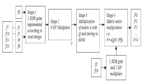
Fig.2. Architecture design
The cosets form the stage 1 and 2 of the architecture. The design for C1, C3, C7 is same, whereas the design for C 5 is different. Cosets C 1 , C 3 , C 7 requires 5 XOR gates and 8 GF multipliers, whereas C 5 requires only 1 XOR gate and 2 GF multipliers. The design for cosets is:
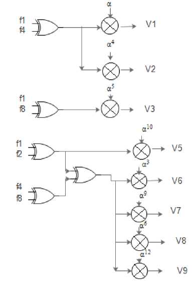
Fig.3. Coset design for C 1 , C 3 , C 7 .
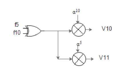
Fig.4. Coset design for C 5 .
In stage 3, the matrix multiplication is performed. The matrices A and Q are multiplied and thereby stored in ROM. The resultant matrix size is 15 x 31. Finally, in stage 4 the matrix and vector are multiplied. Stage 1 and 2 results in a vector, whereas stage 3 results in a matrix. The output of stage 4 is the FFT of the input.
-
V. Common Sub-Expression Elimination Algorithm
In many Digital Signal Processing applications, multiple constant multiplication is widely used. In VLSI design for high-level synthesis, proper optimization of multiple constant multiplication is effective in improving parameters like area and power consumption. To optimize multiple constant multiplications, the Common
Sub-Expression Elimination (CSE) algorithm is used in this paper [5]. The approach used in CSE is initially to identify the identical terms i.e. the common subexpressions present in the equations and then to replace them with a single variable. Thus, by computing the terms only once, results are significantly being reduced in the hardware architecture in VLSI design.
In Galois field, matrix multiplication is performed. Here, the addition is performed via XOR-ing but there are several methods to perform multiplication. In this paper, the multiplication is a linear transform of the form C = AB, where C and B are m- and n- dimensional column vectors, respectively, and A is an m x n constant binary matrix. Here, B represents input variable and C represents output variables. According to this paper, the B column vector is (C . (Pf)) and the matrix A is the resultant matrix of AQ (Refer (6)). So, the CSE algorithm is applied to this matrix – vector multiplication.
Some general steps are involved in carrying out the CSE algorithm. These steps are as follows [5]:
-
1. To identify common patterns present in the transformation.
-
2. Select an appropriate pattern for elimination.
-
3. Compute the pattern only once.
-
4. Eliminate the occurrences of the computed pattern
-
5. Repeat steps 1 to 4 to cover every pattern.
So, by applying CSE algorithm to matrix-vector multiplication there is a significant reduction in a number of XOR gates.
The method suggested in [8] reduces the additive complexities of Cyclotomic Fast Fourier Transform using a weighted sum of the numbers of multiplications and additions. [12] focuses on both area and delay optimization in hardware implementations over GF(2m).
-
VI. Reduced FFT Architecture
To reduce the additive complexity of the FFT architecture, in this paper, the CSE algorithm mentioned in section V has been used. The basic stages of architecture mentioned in section IV remain the same, with the only difference in being applying the CSE algorithm. The CSE algorithm is applied to stage 4. After applying the CSE algorithm to the matrix, the matrix size increases from 15 x 31 to 47 x 63. Due to this, the number of LUTs eventually increases in the final architecture but the additive complexity i.e. the number of XOR gates are reduced significantly.
We have written a synthesizable Verilog code for the different stages of the architecture. First 3 stages of the architecture remains the same, whereas, the architecture design changes at stage 4. Based on the appropriate changes the two architectures i.e. without CSE and with CSE can be compared in terms of LUTs, the number of XOR gates required and delay.
-
VII. Results
The complexity of the proposed architecture has been evaluated considering the synthesis report generated in Xilinx ISE Design Suite. The synthesis report has been generated for two FPGA devices, namely- Spartan 6 and Virtex 5. The results of the GF multiplier used in the architecture are- for Spartan 6 the LUTs required are 9 whereas for Virtex 5 the LUTs required are 8. Number of IOBs remains the same for both FPGA kits.
Table 3. Synthesis Report – GF Multiplier
|
XOR gates |
LUTs required |
IOBs |
Max Combinational path delay |
|
Spartan 6 |
|||
|
4 1 |
9 1 |
12 1 |
6.781ns |
|
Virtex 5 |
|||
|
6 1 |
8 1 |
12 1 |
5.115ns |
The maximum combinational path delay is the maximum delay that would occur for the complete architecture. For cosets C1, C3, C7 since the design is the same the implementation results so generated are same. But, for coset C5 the results are different. For cosets C1, C 3 , C 7 te results are:
Table 4. Synthesis Report – Cosets C 1 , C 3 , C 7
Table 5. Synthesis Report – Coset C 5
|
XOR gates |
LUTs required |
IOBs |
Max Combinational path delay |
|
Spartan 6 |
|||
|
9 1 |
22 1 |
24 1 |
7.791ns |
|
Virtex 5 |
|||
|
13 1 |
20 1 |
24 1 |
5.715ns |
The stage 3 of the architecture is formed by the multiplication of matrix A with Q. The simulation results are:
In the stage 3 of architecture, since only matrix multiplication is involved, no XOR gates are required in this stage.
Finally, the results for the architecture without applying CSE are:
Table 7. Synthesis Report – Architecture without CSE
|
XOR gates |
LUTs required |
IOBs |
Max Combinational path delay |
|
Spartan 6 |
|||
|
121 |
360 |
100 |
10.893ns |
|
Virtex 5 |
|||
|
170 |
340 |
100 |
8.363ns |
The paper mainly focuses on reducing the additive complexity of the FFT architecture. Therefore, the number of XOR gates required before modifying the architecture are 121 and 170 for Spartan 6 and Virtex 5 respectively.
The results after modifying the architecture with CSE are:
Table 8. Synthesis Report – Architecture with CSE
|
XOR gates |
LUTs required |
IOBs |
Max Combinational path delay |
|
Spartan 6 |
|||
|
54 1 |
176 1 |
132 |
6.93ns |
|
Virtex 5 |
|||
|
73 |
173 |
132 |
9.849ns |
After applying CSE, the number of XOR gates are reduced to 54 and 73 for Spartan 6 and Virtex 5 respectively.
-
VIII. Conclusion
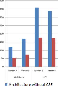
It is clearly evident from the above-mentioned results that the additive complexity of the architecture after applying CSE reduces by a considerable amount. The area of the architecture is also reduced. The number of XOR gates required before applying CSE is 121 and 170 for Spartan 6 and Virtex 5 respectively. Whereas, after applying CSE XOR gates reduces to 54 and 73. Thus, the additive complexity of the FFT architecture is reduced.
Graphically, the comparison between two architectures can be plotted as:
Table 6. Synthesis Report – Matrix A*Q
|
LUTs required |
IOBs |
Max Combinational path delay |
|
Spartan 6 |
||
|
31 |
35 |
6.1ns |
|
Virtex 5 |
||
|
31 1 |
35 1 |
3.979ns |
■ Architecture with CSE
Fig.5. Complexity comparison of architectures.
-
IX. Future Scope
This paper primarily focuses on FFT of 15 elements represented as GF(24). But, based on the technique mentioned in the paper, the FFT for higher powers of 2 can also be generated. To generate DFT over larger fields like GF(211) or GF(212), the algorithm mentioned in [11] can be used. Different multipliers like Karatsuba multiplier, Montgomery multiplier etc. can be used and compared with above-mentioned results.
Acknowledgment
The authors would like to thank Prof. P. Trifonov and Prof. S. Fedorenko for the details of the algorithm used in this paper. The authors would also like to thank Prof. Ali AL Ghouwayel, Prof. Yves Louët, Prof. Amor Nafkha and Prof. Jacques Palicot for the details of CFFT hardware architecture.
References Design of Fast Fourier Transform Architecture for GF(24) with Reduced Operational Complexity
- Trifonov, Peter. "On the additive complexity of the cyclotomic FFT algorithm." In Information Theory Workshop (ITW), 2012 IEEE, pp. 537-541. IEEE, 2012.
- Trifonov, P. V., and S. V. Fedorenko. "A method for fast computation of the Fourier transform over a finite field." Problems of Information Transmission 39, no. 3 (2003): 231-238.
- Ghouwayel Ali Al, Yves Louet, Amor Nafkha, and Jacques Palicot. "On the FPGA implementation of the Fourier transform over finite fields GF (2m)." In Communications and Information Technologies, 2007. ISCIT'07. International Symposium on, pp. 146-151. IEEE, 2007.
- Wu, Xuebin, Zhiyuan Yan, and Jun Lin. "Reduced- Complexity Decoders of Long Reed-Solomon Codes Based on Composite Cyclotomic Fourier Transforms." Signal Processing, IEEE Transactions on 60.7(2012):3920-3925.
- Wu, Ning, et al. "Improving Common Subexpression Elimination Algorithm with A New Gate-Level Delay Computing Method." Proceedings of the World Congress on Engineering and Computer Science. Vol. 2.2013
- R. Blahut, "Theory and Practice of Error Control Codes," Reading Massachusetts: Addison-Wesley, 1983.
- Shu Lin, Daniel J. Costello Jr., "Error Control Coding," Pearson Education, 2005
- Chen, Ning, and Zhiyuan Yan. "Cyclotomic FFTs with reduced additive complexities based on a novel common subexpression elimination algorithm." Signal Processing, IEEE Transactions on 57.3 (2009): 1010-1020.
- Chang, Ching-Hsien, Chin-Liang Wang, and Yu-Tai Chang. "Efficient VLSI architectures for fast computation of the discrete Fourier transform and its inverse." Signal Processing, IEEE Transactions on 48.11 (2000): 3206-3216.
- Fedorenko, Sergei, and Peter Trifonov. "On computing the fast Fourier transform over finite fields." Proc. 8th Int. Workshop on Algebraic and Combinatorial Coding Theory, Tsarskoe Selo, Russia. 2002.
- Wu, Xuebin, et al. "Composite cyclotomic Fourier transforms with reduced complexities." Signal Processing, IEEE Transactions on 59.5 (2011): 2136-2145.
- Zhang, Xiaoqiang, et al. "A low-delay common subexpression elimination algorithm for constant matrix multiplications over GF (2 m)." Industrial Electronics and Applications (ICIEA), 2015 IEEE 10th Conference on. IEEE, 2015.
- Ahmed, Elias, and Jonathan Rose. "The effect of LUT and cluster size on deep-submicron FPGA performance and density." Very Large Scale Integration (VLSI) Systems, IEEE Transactions on 12.3 (2004): 288-298.
- Gao, Shuhong. "A new algorithm for decoding Reed-Solomon codes."Communications, Information and Network Security. Springer US, 2003. 55-68.
- R. Blahut,"Algebraic Codes for Data Transmission," Cambridge University Press, 2003.
