Design of Field Irrigation Multi-purpose Control Device Based on Idle Work Compensation

Author: Liang Zhang, Jishun Jiang, Lina Liu
Journal: International Journal of Image, Graphics and Signal Processing(IJIGSP) @ijigsp
Article in issue: 1 vol.3, 2011.
Free access
In irrigation of a farm well, the power factor of the load is low when the motor operates, because of the long low voltage lines. Long-term use will cause a lot of energy waste. To this question, this paper presents a new type intelligent controller to save irrigation water and energy. The principle of the new type field irrigation intelligent controller that based on AT89LV52 single chip is introduced in this paper. The integration of the low pressure electrical energy reactive compensation control and IC card prepaid multi-user three-phase watt-hour meter management is realized in the system. The energy conservation control, using the low pressure electrical energy reactive compensation, and prepaid multi-user three-phase watt-hour meter are used to realize the saving water management. Who inserts the card who irrigates. The design of hardware circuit, software flow, and experiment results are presented in detail. The results of testing and preproduction in Zibo Billion Electron Co., Ltd show that the design technique of integration controller is novel, and the system has the characteristics of controlling efficiency by reactive compensation, accurate measurement of electrical energy, flexible power consumption management with IC card prepaid multi-users, saving water , low cost, and so on. Therefore, it is especially suitable for power consumption and water resources management in rural well irrigation. The new type intelligent controller can effectively reduce the cost of irrigation and promote rural economic development.
Irrigation, prepaid, watt-hour meter, idle work compensation, energy saving
Short address: https://sciup.org/15012089
IDR: 15012089
Text of the scientific article Design of Field Irrigation Multi-purpose Control Device Based on Idle Work Compensation
Published Online February 2011 in MECS
Accompany with new rural reconstruction, the usage amount of energy and water is getting more and more in rural. The prominent questions which field irrigation needs to solve are how to economize on power energy and water, advocate saving society. The principle of field irrigation energy conservation and saving water integration controller is given in this paper. Because the line of field irrigation is long and the power factor of large-scale motor is lower, long term usage will cause more reactive loss and a wasteful use of power energy. The low pressure electrical energy reactive compensation control can be used to realize electrical energy saving.
By means of prepaid multi-user three-phase watt-hour meter, the management of saving water irrigation maybe come true. The user purchases power energy firstly by IC card, and then consume it.
Following the principle of who inserts card who gets electrical energy, the electrical energy is given when the card is inserted. After the consumption, if you want to purchase electrical energy you must insert your card again. So that the purpose of one meter multi-user integration management and saving water is reached easily. The design technique of integration controller is novel, and the system has the characteristics of controlling efficiency by reactive compensation, accurate measurement of electrical energy, flexible power consumption management with IC card prepaid multi-users, intuitive liquid display, saving water and low cost, and so on[1-3].
-
II. working principle of controller
The intelligent controller is based upon AT89LV52 single chip, which mainly consists of the saving control of low-voltage energy reactive power compensation and prepaid multi-user three-phase watt-hour meter for irrigation saving water control.
A .Principle of Low-voltage Energy Reactive Power Compensation Electrical Energy Measurement
Three-phase power measurement is that 380V AC voltage lines above, Ua and Ia, Ub and Ib phase, Uc and Ic have the same phase on pure resistance load; while the phase difference of line voltage Uab and line electric current Ic is 90°. Similarly, the phase difference of Ubc and Ia, Uca and Ib is 90°. Therefore, it can be used to detect the the phase difference 5 of line voltage Uab and line electric current Ic or Ubc and Ia or Uca and Ib to calculate the power factor of the load. As shown in Fig.1, that is the vector diagram of Ua 、 Ub 、 Uc 、 Ubc 、 Ia. On pure resistance load, the three phase power factor is CGS ^ = 1 , 5 = 90 ° ; On inductive load, the three phase power factor is 0 < cos ^ < 1 , 5 < 90 ° ; On capacitive load, the three phase power factor is
0 > COS ^ > — 1 , 5 > 90 ° . This system detects the phase difference of line voltage Ubc and the line electric current Ia to calculate circuit power factor. Through comparator, the sampling square wave of voltage Ubc and line current Ia is shown in Fig.2.
The equation of calculating power factor can be written as cos^ = cos(5 — 90) = cos(360*T/T — 90) = sin(360*T/T) , where T denotes the difference of high level pulse-width, T denotes the period of three phase AC current; off-line calculation can be used to get the power factor meter, and the resolution of power factor meter is 0.1. When program runs, looks up the table and uses interpolation operation to obtain the actual power factor. In the system, AD7752 is utilized to calculate motor’s actual load, depending on the load size and the size of the power factor, control the access and removal of three-phase power capacitor. As a result of actual control, the power factor can reaches up to 0.95, realizing the low-voltage electrical energy reactive energy control. Power compensation capacitors adopts four-level compensation power capacitor, which has ladder distributed capacitance capacity.
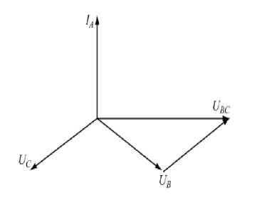
Figure 1. Measurement vector diagram of three-phase power factor
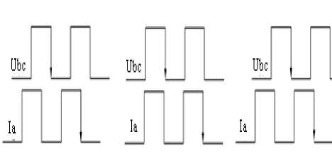
(a) pure resistance load (b) capacitive load (c) inductive load Figure 2. Sampling square wave of of voltage Ubc and line current Ia
B. Principle of Multi-user Three-phase Watt-hour Meter Realizing Control of Saving Water Irrigation
Irrigation saving water control is realized by the IC card prepaid multi-user three-phase watt-hour meter. The watt-hour meter mainly includes the three-phase electrical energy measurement electric circuit AD7752, IC card read-write control electric circuit, the HS12864-15B liquid crystal display electric circuit, the relay control and lacks examines modules and so on. The working principle of watt-hour meter is separately transforms the three-phase AC voltage and the electric current into the small signal after the voltage divider and the current transformer, and then passes them to measurement electric circuit AD7752, AT89LV52 measures power consumption and controls power supply. The pre-payment management is realized by buying electricity first and then uses it. Through inserting the card to use and then retrieve the electricity, the multi-user power supply and the power failure management will come true.
This saving water controller may supply several hundred household users to use. When the user IC card is inserted into watt-hour meter, first carries on the IC card cryptographic check, distinguishes this user card whether it is user card of this village. If it is this village’s user card, carries on the IC card read-write and the power supply, then if not, carries on the power failure control and shows “it is not my village’s card” at the same time.
This system realizes who inserts the card, who uses electricity, who irrigates; After the irrigation had ended, inserts the card and take back electric energy. This is a good method to realize the multi-user irrigation saving water control.
-
III. The desigh of controller hardware
The intelligent controller is designed based on AT89LV52 single chip. AT89LV52 has 8k byte flash memory, third-level encryption program memory, 256 byte internal RAM, 32 numbers of programmable I/O lines, three numbers of 16-bit timer/counters, one 6 vector two-level interrupt structures and so on. The interface circuit uses the I2C bus structure. AT89LV52 is a cost-effective 8-bit single chip that is more suitable to switch quantity input signal detection. Intelligent controller mainly includes power factor detection circuits, relay control capacitance compensation control circuit, three-phase power measurement circuit AD7752, IC card read-write control circuit, HS12864-15B LCD display circuit, magnetic latching relay control and lack phase detection module circuit. The structure Diagram is shown in Fig.3[4-6].
A. Power Factor Detection Circuit
The power factor examination electric circuit takes a sample from the line voltage Ubc using the voltage transformer, the current transformer takes another sample from the line electric current Ia. After filter processing, sample signal enters the LM393 comparator and gain square-wave signal separately, turns on AT89LV52 after the electro-optical isolation through P14, P15, catches the pulse width time difference T of the two square-wave signals, and then through table look-up interpolation calculates power factor. When the time happens to fall on the time point in Table 1, directly gains the power factor from look-up table1; when the time falls between two time points (t1, cosa1) and (t2, cosa2) , let the two power factor ,corresponding to the two time points , as two coordinates,uses interpolation method to calculate the power factor.
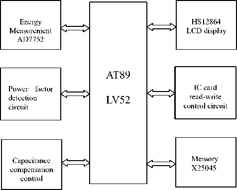
Figure 3. System structure diagram
Two interpolation formula: cosa=(cosa2-cosa1)* (t-t1)/(t2-t1)+cosa1 ; By increasing the number of data in Table1, uses interpolation measure method to ensure that the accuracy of the power factor is 0.1 magnitude.
TABLE I. L ow - voltage circuit power factor
MEASUREMENT TABLE
|
Time T ( ms ) |
0.0 |
1 . 0 |
2.0 |
3.0 |
4.0 |
5.0 |
|
degree ( ° ) |
0 |
18 |
36 |
54 |
72 |
90 |
|
PF ( Capacitive ) |
0 |
0.3090 |
0.5878 |
0.8090 |
0.9511 |
1.0000 |
|
Time T ( ms ) |
5.0 |
6.0 |
7.0 |
8.0 |
9.0 |
10.0 |
|
degree ( ° ) |
90 |
108 |
126 |
144 |
162 |
180 |
|
PF ( inductive ) |
1.0000 |
0.9511 |
0.8090 |
0.5878 |
0.3090 |
0.0000 |
B. Power Measurement Circuit
ADI's low power chip AD7752 is adopted in a three-phase power measurement. In addition to the ADC, filters and multiplication circuit, AD7752 incorporates digital circuit, which can effectively eliminate the sharp pulse interference signals. On three-phase AC power circuit, samplings voltage and current signal, calculates the power, through integral transforms it into electrical energy pulse output. The pulses of output terminal CF via isolator PC817 access INT0 interrupt pin of AT89LV52, CPU measures power energy. Use state combination of S0 and S1 CF to adjust output pulse constant. The relationship between power and pulse: W = M/C , where W denotes power, expressed in kWh, M is the number of pulse count, C is the meter pulse constant, select C = 3000, 3000 per kWh for a pulse. As shown in Fig.4.
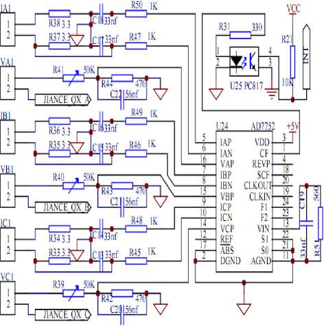
Figure 4. Power measurement circuit
C. IC Card Read-Write Circuit
The IC card adopts SLE4442 encryption card of SIEMENS Corporation. The IC card control circuit consists of HD4442 cassette and the protection circuit, as shown in Fig.5, two unused pin slightly. Cassette’s replacement RST, clock CLK, data SD, the card input CIN connect withP00, P01, P02 and P03 of AT89LV52 separately. The AT89LV52 P0 port interior has pull-up resistor, not need pull-up resistor in addition. There is a normly open micro-switch in the bottom of the cassette. When no card is inserted , switch off and the CIN pin has a high level. When the card is inserted, close the switch and the CIN pin has a low level.AT89LV52 can judge whether there is a IC card through inquiring the RF3 pin level. When the card is inserted, IC card and the contacts are closely linked.AT89LV52 realizes to the IC card read-write control operation through P01 and P02.
The card protection circuit is accomplished by triode Q1. The power source VCC of IC card uses triode Q1 output to realize power supply. This is designed to effectively prevent a short circuit, in case the cassette has been artificially inserted into sheet metal.
In order to read the data message of the card, when examines the existence of the card, delays 10ms to vibrate, then carries on the IC card read-write again. As shown in Fig.5.
D. Serial Memory
Serial storage adopts X25045 low power chips of XICOR Company. The chips have three functions that are watchdog timer WTD, power supply voltage monitoring and 512 bytes of serial E2PROM storage. WTD can be settled up to 200ms, 600ms, 1400ms feeding the dog timer interval, software programming has been written into X25045. During the normal operation of the program, WTD receives a trigger signal at regular intervals to ensure that the program is running properly. If the trigger signal is not received in scheduled interval at the end of the WTD, then through X25045 RESET pin outputs a high level signal, triggers the starter to reset preventing the program from running out. As serial storage chips, 512 bytes are used to store reactive power compensation parameters and meter user information differently. It uses the SPI protocol bus interface to connect with AT89LV52.
E. LCD Display[7-9]
The features of HS12864-15 series Chinese graphic LCD module mainly are determined by its controller ST7920. As the controller and drive, ST7920 provides 33 roads COM and 67 roads SEG output. In cooperation with ST7921, it can drive 256 * 32 dot matrix LCD driver at most. HS12864 series product of HOLTEK Industrial Co, Ltd includes HS12864-12, HS12684-15B and HS12864-15C.
The LCD display adopts HS12864-15B LCD display driver chip of HOLTEK to achieve 4 rows each row 16 characters LCD digital display and Chinese character prompt. HS12864-15B is built in Chinese character library memory LCD driver, which includes control and timing circuits, display RAM, LCD driving and bias, watchdog timer, etc. Product software has the function of mixed text and graphics display, clear screen, cursor homing, display switch, hide cursor, flashing display font, cursor and display movement, vertical screen rotation and sleep mode. It uses serial interface between AT89LV52 and itself, just three wires. P10, P11, P12 and P13 of AT89LV52 connect to four pins respectively to control the refresh display RAM buffer. The four pins are its RST, E Chip Selection, W/R read-write and RS serial data respectively. As shown in Fig.5.
F. Capacitance Compensation Control Circuit
As shown in Fig.5, capacitance compensation circuit uses the port P04 and P07 of AT89LV52 to realize four channels latching relay control. The figure gives relay control circuits in section, after PC817 opto-isolator, control COMS tube IRL1530, drives three-phase magnetic latching relays, and realizes low-voltage electrical energy saving control based on reactive power compensation. The relay control of watt-hour meter uses the pin P06 and P07 of AT89LV52 to enable relay control, completing the power supply and power failure control.
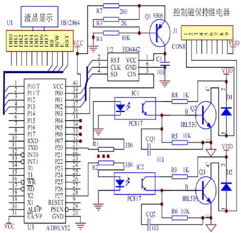
Figure 5. Display and relay control circuit
G. Lack Phase Detection Circuit
Phase voltage of three-phase motor, Va, Vb, Vc, and the neutral point V0, are taken respectively in lack phase detection. Output pin signal separately through 75K resistance, rectifier and capacitance filtering access the opto-isolator EL817, as shown in figure 7. Three-phase voltage switch access P22, P23, P24 pin of AT89LV52, judging whether the phase lack. Once detect lack phase, detect again after 2 seconds delay. Cut off power supply immediately afterwards phase lacking is confirmed again.
In the system, pulsed output of AD7752, relay control, detection of lack phase signal input all adopt opto-isolator. of which two kinds, high-speed 6N137 and universal EL817, is used in system. Data acquisition and output uses high-speed optocoupler 6N137 to isolate. The input and output of switch use opto-isolator EL817, which directly control the solid state relay, complete bypass relay control and the control of sound and light alarm. In system, the transmission of electrical signal through optical coupling, can improve anti interference ability of the system.
-
IV. The desigh of software
System outage resource allocation :
-
INT0: external interrupt 0 for pulse measurement.
T0: 10ms timing to generate an interrupt.
INT1: Three-phase power factor control of pulse capture.
T1: for timing.
T2: three-phase power factor pulse width capture timing.
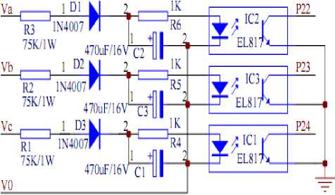
Figure 6. Lack phase detection circuit
The software program of controller includes initialization, the main program, the power factor detection and compensation control program, IC card read-write handler, interrupt handler, timer handler, HS12864-15B display and control program, power energy measurement and power-handling procedures, systems self-inspection and software anti-interference processing eight modules.
The system must be initialized each time, the initialization program includes timer, interrupt and other work setting of AT89LV52 singlechip. Also it includes the setting of control word for serial LCD driver chip IC HS12864-15B. In a sub-module, power factor detection and compensation program, complete power factor detection and access control of capacitor. INT interrupt handlers complete energy measuring, energy is temporarily stored in RAM memory of AT89LV52.Each time the cumulative power reaches to one coulomb, then write on-chip EEPROM in the corresponding address. The battery power of the Watt-hour meter is divided into user remaining capacity and multi-user cumulative consumption of electricity.AT89LV52 examines size of the user remaining capacity , if low energy meter LED is blinking, remind the user of needing to purchase electricity. On-chip EEPROM read/write program completes writing and reading of serial data. Display control program HS12864-15B realizes Chinese character prompting, LCD displays the user code and the village yards, remaining capacity, cumulative consumption information in turn, the display interval is 5 seconds. IC card handler completes the IC card password verification, read-write and card type judgement and then operates other task correspondingly. IC card types are divided into five types: clear cards for factory original settings of Watt-hour meter; set cards is used to set the watt-hour village code and load threshold; changing meter cards is used to swap out all the information in the meter and then feeds into the new replacement Watt-hour meter; reading cards cut back the user information and the accumulated consumption of electricity on the meter, and then use the card reader sending information to the host computer sales electro management system; user card is used for account recharge through the computer management system. The first four cards is used by power management departments, the user only have the user card. The current user is in the process of using electricity, when other users insert user card , power meter will indicate that someone is using electricity.The inserted SIM card only remove the insert-user's information in the meter, not producing an effect on normal use. Currently no user uses electricity, user inserts the user card and the card information is written to the meter, displays the value of buying power at the same time, when the card is pulled out, power supply will go on immediately;after inserting the user card again, the user information is wrote in power meter to the IC card, and indicates that the removal of remaining power, immediately power off. If the current user is used in electrical power, the power supply failed suddenly, the power meter comes into the power failure handler, remaining capacity and the cumulative consumption of the current user is stored in
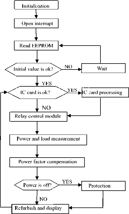
Figure 7. Flow chart of main program
EEPROM of the X25045. If the current user is in the process of using electricity and detects phase lacking, watt-hour will store current information and immediately power off. If excess load occures in using electricity, then power will be failure. The system self-check and the software antijamming disposal procedure is used to complete data checking and system self-diagnosis. Work process main program flowchart of controller is shown in Fig.7, the other sub-modules flowchart is omitted.
-
V. TESTING RESULT AND ERROR ANALYSIS
-
A. Testing Result
The error test and the running test have been made in the Zibo Billion Electron Co., Ltd., the power factor compensation efficiency achieves 0.98. The electrical energy measurement takes the standard table with 0.1 level of standard electronic formula electrical energy table as checking table, the IC card electrical energy table as the measured table 2. The rated load of electrical energy table is 40KW; the Billion Electron Co., Ltd. carries on the test viewing on different load situation. As space is limited, only lists measured data when the load is 1KW, 10KW, 40KW as shown in Table 1. The test results indicated that the IC card electrical energy meter error is smaller than 1%, belonging to 1.0 level of standards.
TABLE II. testing value of normal meter and testing meter( load 1KW,10KW,40KW)
|
Load(KW) |
Normal meter(kWh) |
Tested meter(kWh) |
Error(%) |
|
1.00 |
2.000 |
1.993 |
-0.350 |
|
10.00 |
2.000 |
1.997 |
-0.150 |
|
40.00 |
2.000 |
1.995 |
-0.250 |
-
B. Error Analysis
There are sampling voltage, sampling current, the power supply three factors, afecting energy measurement accuracy of the intelligent controller. The current signal can be Samplinged, using high-precision low current transformers. High stability resistors can be used to divide sampling voltage. Sampling the voltage signal , using a small capacitor filter.These devices should have low coefficient of temperature drift to ensure that the sampling voltage is stable. It will be better , if the supply voltage for AD7752 has higher stability and small ripple. Through the experiments we can know that there are several methods to reduce the electrical energy measurement error. Firstly, adjust the sampling matched resistance of AD7752 to the precise value. Secondly, require that the value of matching resistor must have small changes, when the temperature changes. Thirdly, during electricity measuring progress, when the power supply and use, mantissa portion of electricity is less than 0.01, the remaining pulse value should be accessed together, thus cumulative error caused by a shortage of accessible 0.01 degree power loss could be avoided.
-
C. Electro Magnetic Compatibility Technology
In order to prevent the intelligent controller from being interfered with the disturbance pollution of power system . In the hardware system reset, the system utilizes the watchdog and reset technologies. The timer WTD of feeding the dog is set to 600 milliseconds. During normal operation of the program, the watchdog timer will receive a trigger signal within a time interval to ensure the program is running. If the watchdog timer havenot received the trigger signal within the time interval, through the RESET pin , X25045 will output a high level signal, which can touch off intelligent control device reset to prevent the program from running out. Reset does not change the power information, time settings and other data information, however it will check the data information. By reading the first and second same storage partition in X25045, find the correct data.
In the system, AD7752 pulse output and relay control terminal, respectively, use the 4N35 optical isolators for optical isolation. The optical isolators adopt 500 ohm current limiting resistor, to ensure reliable coupling transmission of pulse signal. The optical isolators are used to achieve light coupling to transmist signal and isolate the interference source and vulnerable interference , improving anti-interference ability of system. Moreover in the system cabling, analog signal and digital signal have different traces. This design can avoid the impact of the analog signal on digital circuits.
-
D. Data Processing and Protection
As for the data storage of intelligent control device, first, important data storage area in the singlechip internal RAM and X25045 serial storage area are bisected, where the first area is the data application areas, the second area is the data backup area. During normal operation of the program, data temporarily is stored in RAM of singlechip, each group of data must be carried out decimal check, then further accumulation and check are required. Confirm this group of data when the test is right, calculate the checksum and get ready to write in serial memory. The check data and the checksum are stored in the first partition and second partition of X25045 serial storage area. Each time a zone is stored, confirm whether the check is right. If there is no wrong, then continue to the next area of storage; If an error occurs, use the data of backup partition to update the storage.
During normal operation of the program, when the power reachs to a kilowatt hour, the data within X25045 will be updated timely. As far as sudden power outages and other special circumstances, update the data immediately. In addition, regarding to the stored data, if the balance of electrical power is less than 0.01 kilowatt hour, then records the corresponding number of pulses, ensuring a highly degree consistent with data. Owing to data backup of two same storage partitions, the accuracy and reliability of data greatly get a huge increase which can avoid data loss and occurrence of the wrong data. Pulse group experimental test and actual operation indicate that the data processing method can achieve better results.
References Design of Field Irrigation Multi-purpose Control Device Based on Idle Work Compensation
- Zhang Ruimei. Opens the Swiss US. “15” saving water irrigation development existence question and countermeasure [J]. China countryside water conservation water and electricity, 2007, (02):14-16.
- Jiang Jishun. The smart card pays expenses the multiuser three-phase agriculture to fill the table design in advance. China countryside water conservation water and electricity, 2010, (01): 17-19.
- Luo Jianen. The well ditch saving water irrigation application effect studies the [J]. China countryside water conservation water and electricity, 2008, (07):36-38.
- Qu Qingchang. “Key technology to three-phase electric meter and high voltage electric power measurement.” Acta Metrologica Sinica, 2007, vol28: 25-30.
- GaoYun-Peng, Teng Zhao-Sheng, Liu Peng. “Design of three-phase multi-functional harmonic energy meter.” Journal of Hunan University Natural Sciences, 2008, 35(9): 53-57.
- Al-Khateeb Tarik, Blundel Martin. “An electronic meter for measuring the saving in electrical power.” The Ninth Arab International Conference on Solar Energy (AICSE-9), Kingdom of Bahrain, 2007,4 (209):328-333.
- Bu Zhengliang, Yin Xianggen, Tu Guangyu. “Development of HV Watt-hour meter.” Automation of Electric Power Systems, 2006, 30(19): 89-93.
- ZHUANG Zhi-hong. “Field Irrigation Intelligent Control System Based on PIC Singlechip.” Journal of Anhui Agricultural Sciences,2010, (30):11-17.
- ZHANG Ring, YUAN Shou-qi, CHENG Li. “Present Situation and Prospect of Automatic Control Technology in Water Saving Irrigation at Home and Abroad.” Drainage and Irrigation Machinery,2010,(02):13-18.
