Design Of High Performance Reconfigurable Routers Using Fpga

Автор: R.Parthasarathi, P.Karunakaran, S.Venkatraman, T.R.DineshKumar, I.Hameem Shanavas

Журнал: International Journal of Information Engineering and Electronic Business(IJIEEB) @ijieeb

Статья в выпуске: 4 vol.4, 2012 года.

Бесплатный доступ

Network-on-chip(NoC) architectures are emerging for the highly scalable, reliable, and modular on-chip communication infrastructure platform. The NoC architecture uses layered protocols and packet-switched networks which consist of on-chip routers, links, and network interfaces on a predefined topology. In this Project, we design network-on-chip which is based on the Cartesian network environment. This project proposes the new Cartesian topology which is used to reduce network routing time, and it is a suitable alternate to network design and implementation. The Cartesian Network-On-Chip can be modeled using Verilog HDL and simulated using Modelsim software.

Еще

Network-on-chip, Cartesian Network, Router, Verilog HDL, Architecture

Короткий адрес: https://sciup.org/15013138

IDR: 15013138

Текст научной статьи Design Of High Performance Reconfigurable Routers Using Fpga

Published Online August 2012 in MECS

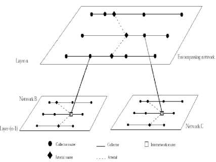
Cartesian routing is a fast packet routing mechanism intended for geographic addresses and can effectively accelerate the packet routing process within a local or metropolitan environment. The wide area Cartesian routing described in this paper is an extension of the Cartesian routing algorithms designed to make the exchange of internet work packets between geographical regions possible. It also introduces a new hierarchical structure for the entire Internet. The proposed Internet is viewed as a hierarchy of networks consisting of routers.

At the highest level of this hierarchy, major routers exchange packets between large geopolitical areas such as countries, states, or provinces. At the lowest level of the structure, packets are routed between local routers in small geographical regions ranging from an office to a small town. There are only four layers in this structure and at each layer Cartesian routing is employed to send packets from the source router to the destination .

A Cartesian network consists of a set of collectors and one or more arterials

CARTESIAN ROUTER

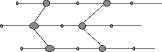
Fig: 1 Cartesian router

Each collector is a chain of collector routers running east-west and sharing common latitude. Collector routers have two side ports (east and west) to exchange packets’ horizontally’. Each collector router also has a bottom Port which allows it to connect to a set of local hosts. Arterials exchange packets between collectors.

Each arterial router, except the most northerly and the most southerly has, at least, four ports (north, south, east and west). Arterials need not share a common longitude. In a Cartesian network, the imposed topological structure relieves each router from maintaining routing tables. Each router is bound to a unique pair of addresses, the state information is minimal, and each router maintains the accessibility of arterials to its west andeast.

  • 2.1    Cartesian Network Initialization

  • 2.2    Cartesian Routing

  • 2.3    Wide Area Cartesian Networks

In Cartesian routing, each arterial issue Arterial This Way (ATW) control packets during its initialization process. An ATW tells the receiving collector router if an arterial is accessible through the incoming port. An ATW also specifies what kind of connection is accessible via the incoming port: north, south, north and south or neither. Upon receiving an ATW, each collector router updates its Arterial Direction Indicator (ADI) and forwards the ATW to the opposite port. ATWs are also used to establish.

Virtual Arterials, constructed in situations where it is physically impossible for an arterial to span two collectors. The ADI points in the direction of the arterial router (i.e., east or west) and indicates whether the arterial router has a connection to the north, the south, or both. Figure 1 illustrates a Cartesian network.

Packets can arrive on either a west or east port of a collector router. Packets intended for different latitude are forwarded out the opposite port from which they are received.

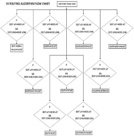
The ADI determines the packet’s initial direction on the collector router when a packet arrives on the bottom port of a collector router. In deciding a packet’s initial direction, the router first compares the packet’s destination address with its own address. The packet will be forwarded in the direction of the destination if the

Table 1:4-port routing algorithm

ADDRESS FUNCTIONS Dest_lat=node_lat Dest_long=node_long Router keeps the Packet Dest_lat>node_lat Dest_long>node_long Packet routed to North Port Dest_latnode_long Packet routed to South Port Dest_lat=node_lat Dest_long>node_long Packet routed to East Port Dest_long

A Cartesian network provides a straightforward topological structure that relieves collector routers from the need to maintain routing tables. However, it would be unrealistic to implement a single worldwide Cartesian network. Such a widespread Cartesian network, for example, requires every packet destined for a router with the same latitude identifier as the source router’s latitude identifier to visit all the collector routers. It is also necessary for such a network to have one collector for every possible latitude. These limitations suggest that implementing a single worldwide Cartesian network would be impractical. An alternative to a worldwide Cartesian network is to create a set of smaller Cartesian networks and implement a mechanism for interchanging packets between them. One approach to interchanging packets between Cartesian networks is to forward packets towards their destinations.

When a packet reaches the boundary of a network it “falls off” the edge and is delivered to a special router to be forwarded towards the destination address. The process of routing a packet from one network to another using this approach becomes problematic when networks are interleaved or overlapped .Two networks are considered interleaved if there is at least one collector router on one of the networks where its longitude identifier lies between the longitude identifiers of two collectors from the other network and its latitude identifier lies between the latitude identifiers of two collectors from the other network. Figure illustrates two interleaved networks. Two networks are said to be overlapped if there is at least one collector router on one of the networks where its longitude identifier lies between the longitude identifiers of two collectors from the other network and all three of them share the same latitude identifier. Figure illustrates two overlapped networks.

An alternative method for delivering a packet to its destination is to find the destination network address and then to route the packet to the destination network by using Cartesian routing algorithms. This implies that each network must be identifiable using the packet’s destination address. If we assume that each network has a rectangular shape, recognizing the destination network is a matter of comparing the packet’s destination address with the network’s boundaries. However, there are a number of reasons to assume that it would be unrealistic to expect networks to have rectangular borders: geographical barriers and political jurisdictions, for example. Since Cartesian routing uses latitude and longitude pairs to identify the source and the destination addresses of packets, this information is not sufficient to determine to which network a collector/arterial belongs in the case of interleaved and overlapped networks. This, in turn, suggests that an additional set of information is required to identify to which network a collector or arterial is connected. To achieve this, the authors propose a hierarchical structure for Cartesian networks. In the next section the possibility of multiple-layer Cartesian networks as a solution for interchanging packets between arbitrary shaped interleaved and overlapped Cartesian networks are explained. In the remainder of this paper, the terms “wide area Cartesian networks” and “multiple-layer Cartesian networks” are used interchangeably.

Figure.1 Router Structure

  • III.    MULTIPLE-LAYER CARTESIAN NETWORKS

  • 3.1    DMM

Multiple-layer Cartesian networks impose a new set of topological dependencies among a set of Cartesian networks, such that interchanging packets between networks is feasible without creating and maintaining routing tables. Generally, in multiple layer Cartesian networks, the idea of Cartesian networks is expanded in a larger scale using a hierarchical structure.

Multiple-layer Cartesian networks have a hierarchical structure. The highest layer of the hierarchy is a single Cartesian network. Each underlying layer consists of a set of mutually disjoint Cartesian networks (i.e., they are physically disjoint and share no collector or arterial router); however, networks in the same layer can be interleaved or overlapped. The PCM (Packet Counter Module) strips the destination address from the packet. It counts the incoming packet bits and Sets the RECEIVING-ADDRESS flag when the first bit of the address is read. The ACM (Address Counter Module) keeps the track of the number of address bits that have been read.

Figure 2. Decision Making Module

It indicates which portion of the address is being received (latitude or longitude) and if the entire address is received, it sets the ADDRESS-RECEIVED flag. When the ADDRESS-RECEIVED flag is set, the IPS is told to keep the packet. The RAP stores the router address and pipes it our serially so that it can be compared with the incoming destination address.

The Router address is static value, and is kept in nonvolatile memory for long term storage. The ADM simply compares the ith bit of the destination address to the ith bit of the router address as the destination address is read in to the DMM. If the DA does not equal to RA, the ADM tells the incoming packet storage (IPS) module to destroy the stored packet.

Figure 3.An encompassing network and two encompasses network

3.2 Router Identification

Figure 4. XY Routing Algorithm flow chart for 8 port network

In a Cartesian network, each router is bound to a Cartesian address. Whereas, in a multiple-layer Cartesian network, each router is bound to an identifier. The identifier of a router at layer-m of an m-layer Cartesian network is the same as its Cartesian address. An identifier of a router at lower layers is the identifier of its immediate encompassing router, followed by the Cartesian address of the router itself, meaning that an identifiers an ordered list of Cartesian addresses. For example, routers at layer-(m-1) maintain the Cartesian address of the router that represents the network to which they belong, followed by their own Cartesian address.

In general, in an m-layer Cartesian network, each router at layer-n maintains a list of (m-n+1) ordered Cartesian addresses, where. For example, routers at the lowest layer of the hierarchy, layer-1, which are connected to local hosts through their bottom ports, are bound to m ordered Cartesian addresses: m-1 correspond to the identifier of the encompassing router at layer-2, and one, the Cartesian address of the router itself. Figure 5 illustrates the hierarchical addressing structure of an identifier for a router at layer-n of an m-layer Cartesian network. The hierarchical addressing structure overcomes the problems with both interleaved and overlapped networks

Since every router in the hierarchy has a unique address. It also enables a router in a network at layers to determine if a packet is local to the network or not. A packet is said to be local to a network if the network encompasses the destination address of the packet. A router can determine this by comparing the most significant m-n Cartesian addresses of the packet’s destination address with the first m-n Cartesian addresses of its own identifier.

PACKET FORMAT

SOP^-Start of Packet(6 bits—6Ъ111111) EOP^End of Packet(6 bits—6’b111111)

M ^Cast(Unicast-4’b0000,Multicast-’b0001) DLAT^Destination Latitude

DLON^Destination Longitude

SOP M DLAT DLON SLAT SLONG DATA EOP

Figure 5. Packet Routing

In an m-layer Cartesian network, each collector router at layer-n is bound to an identifier which is a list of m-n+1 Cartesian addresses. A packet can enter a network at layer-n through the bottom port of a collector router or the top port of the network’s IR. Packets received on the bottom port of a collector router are either local or nonlocal to the network, as described above. When a packet is found to be local, that is, the network encompasses the destination address, the router “tags” the packet as a local packet by setting a single bit of the packet’s address called the local bit. When a packet is local to a network at layer-n, the (m-n+1)th Cartesian address of the packet’s destination address is used to route the packet in the network using Cartesian routing algorithm. For example, at layer-m, the first Cartesian address is used for Cartesian routing, while at layer-1 the mth address is used. When a packet is received by a router on its bottom port, the address is Cartesian address of the encompassing router at layer-(m-1) inspected. Non-local packets must be sent towards the network’s IR in order to be delivered to the encompassing network. The router clears the local bit and forwards the packet towards the IR. Forwarding a packet to the IR requires that each collector router and arterial maintains an Internetwork Router Direction Indicator or IRDI. The IRDI determines if the internetwork router is accessible through the west port, east port or neither, in the case of collector routers; or whether it is accessible through the north port, south port or neither, in the case of arterials. If the packet is determined to be non-local, it is forwarded in the direction specified by the IRDI. When the IRDI indicates that IR is not accessible, the packet is dropped and a message is returned to the source notifying that the destination address is not reachable.

A collector router that receives a packet on its west or east port checks the local bit; if set the Cartesian routing algorithm is employed to route the packet, otherwise the packet is forwarded to the opposite port. When a packet enters a network through the top port of the network’s IR, the packet is guaranteed to be local, since this has already been verified by the encompassing network. Upon receiving the packet, the IR sets the local bit and then applies the Cartesian routing algorithm on the (m-n+1)th Cartesian address of the Packet’s destination address.

  • IV.    SIMULATION RESULTS

    Figure 6.Simulation Results for Packet Hold


Figure 8. Simulation Results for North-east Port

Figure 9.Simulation Results for South-west Port

Figure 10. Simulation Results for South-east Port

Figure 11. Simulation Results for Packet Discarded

V.CONCLUSION

In Previous work, they designed conventional router which uses a routing table to determine whether to keep, forward or discard the packets. As networks grow in size, the memory requirements of the routing tables increases proportionally. The average search time increases as the routing table increases. ASIC based router design.

In our proposed work, the New Cartesian network is designed, which is Independent of routing table. It is the High speed network transmission when compared with existing work.

Список литературы Design Of High Performance Reconfigurable Routers Using Fpga

  • Lee, Se-Joong Lee, and Hoi-Jun Yoo, "Low-Power Network-on-Chip for High-Performance SoC Design Kangmin" "IEEE transactions on very large scale integration (vlsi) systems," vol. 14, no. 2, february 2006.
  • W. Dally et al., "Route packets, not wires: On-chip interconnection networks,"in Proc. Des. Autom. Conf., Jun. 2001, pp. 684–689.
  • L. Benini et al., "Networks on chips: A new SoC paradigm," IEEE Computer,vol. 36, no. 1, pp. 70–78, Jan. 2002.
  • D. Bertozzi et al., "Xpipes: A network-on-chip architecture for gigascale system-on-chip," IEEE Circuits Syst. Mag., vol. 4, no. 2, pp. 18–31,2004.
  • E. Rijpkema et al., "Trade offs in the design of a router with both guaranteed and best-effort services for networks on chip," in Proc. Des., Autom. Test Europe Conf., Mar. 2003, pp. 350–355.
  • V. Nollet et al., "Operating-system controlled network on chip," in Proc. Des. Autom. Conf., Jun. 2004, pp. 256–259.
  • C. Wu and H. Chi, "Design of a high-performance switch for circuit-switched on-chip networks," in Proc. Asian Solid-State Circuits Conf. , 2005, pp. 481–484.
  • M. A. Al Faruque, T. Ebi, and J. Henkel, "ROAdNoC: Runtime observability for an adaptive network on chip architecture," in Proc. IEEE/ACM Int. Conf. Comput.-Aided Des. (ICCAD) , 2008, pp. 543–548.
  • H. Jingcao, U. Y. Ogras, and R. Marculescu, "System-level buffer allo-cation for application-specific networks-on-chip router design," IEEE Trans. Comput.-Aided Des. Integr. Circuits Syst. , vol. 25, no. 12, pp. 2919–2933, Dec. 2006.
  • Y.-C. Lan, S.-H. Lo, Y.-C. Lin, Y.-H. Hu and S.-J. Chen, "BiNoC: A bidirectional NoC architecture with dynamic self-reconfigurable channel," in Proc. Int. Symp. Netw.-on-Chip, 2009, pp. 266–275.
  • C. Xuning and L. Peh, "Leakage power modeling and optimization in interconnection networks," in Proc. Int. Symp. Low Power Electron.Des. (ISLPED), 2003, pp. 90–95
  • M. Vestias and H. Neto, "Router design for application specific network-on-chip on reconfigurable systems," Field Program. Logic Appl., vol. 1, pp. 389–394, 2007
Еще
Статья научная