Design of model free sliding mode controller based on BBO algorithm for heart rate pacemaker

Author: Ekhlas H. Karam, Tariq Tashan, Eman F. Mohsin
Journal: International Journal of Modern Education and Computer Science @ijmecs
Article in issue: 3 vol.11, 2019.
Free access
A modified Model-Free Sliding Mode Controller (MF-SMC) scheme, which based on the Biogeography-Based Optimization (BBO) algorithm is suggested, to regulate the heart rate since it is difficult to derive a suitable model for the control algorithm, therefore the traditional control algorithm cannot perform efficiently. Also, a smoothing boundary layer is used to eliminate the chattering in the MF-SMC control signal. Results of simulation effort show that overshoot less and fast performance is achieved with stable convergence for the tracking regardless of the heart rate model to be controlled.
Model free controller, SMC controller, BBO algorithm, heart rate (HR), pacemaker
Short address: https://sciup.org/15016837
IDR: 15016837 | DOI: 10.5815/ijmecs.2019.03.05
Text of the scientific article Design of model free sliding mode controller based on BBO algorithm for heart rate pacemaker
Published Online March 2019 in MECS DOI: 10.5815/ijmecs.2019.03.05
The human heart is the muscle organ which responsible for the operation of the rest organs in the body, by pumping the blood inside the vessels out of rhythmic and frequent contractions [1]. The heart muscle's contractions primarily determined by electrical signals coming from the upper cells of the right atrial chamber of the Sinoatrial (SA) node, that generates a regular heartbeat, and considered as a natural pacemaker [2]. The human's Heart Rate (HR) diverged usually in the range of (60-100) bpm. HR around 72 bpm is the normal case, and for the old age it decreases to about 60 bpm. The HR can be increased or decreased, in order to provide oxygen according to physical requirements [3]. If there is any problem with the heart's conduction system shown in Fig. 1, several treatments, including an artificial pacemaker, are used. The pacemaker fires an electrical impulse if it detected any abnormality in the HR, which may occur due to changes in the electrical activity of the heart [4].
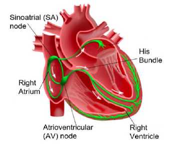
Fig.1. Electrical conduction system of the human heart [5].
Since the pumping speed is related to the HR, it is difficult to derive a suitable model for the control algorithm, therefore the traditional control algorithm cannot perform efficiently. The MF-SMC based on the BBO algorithm, to optimize its parameter, is used in this paper for heart rate regulation. The model-free solely depends on input and output data of the controlled plant.
The rest of this paper is organized as follows: Section 2 presents information about the pacemaker device. Section 3 explains the mathematical model of the heart. Section 4 describes the MF-SMC details, while Section 5 illustrates the BBO algorithm. Section 6 addresses the simulation results and analysis of the proposed controller, and Section 7 provides the final conclusions.
-
II. Pacemaker
The pacemaker is a medical device that regulates the rhythmic work of the heart using electrical pulses. These pulses are delivered by the electrodes which are in contact with the heart muscles [6].
The pacemaker has two main parts: an electronic pulse-generating unit and a pulse-driven lead to the heart. Generally, there are two functional units of the pacemaker, the first is sensing the human resources of the patient by the sensor circuit, and the second is sending electrical signals to the heart muscles by the output circuit [4]. This electrical signal is used to control the HR of the patient. If the HR becomes too slow or fast, the pacemaker senses the abnormal signal and begins to send regular signals to the heart muscles, which push the heart to shrink at a rate appropriate to the normal rhythm of the patient's heart. During arrhythmias, the heart is not able to pump the right amount of blood, to meet the body demand of oxygen. Therefore, the primary goal of the pacemaker is to treat anomalies of the rhythmic in the heart to resume a normal lifestyle.
Practically, there are two main types of pacemaker [3]:
-
• Internal pacemaker: It is a permanent device because of the inability of the heart to perform its functions naturally due to disrupt.
-
• External pacemaker: This device is used in emergencies when a heart blockage occurs during heart surgery operations and used for a short period of time.
Fig. 2 shows an internal pacemaker for the heart, which is in focus here.
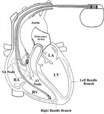
Fig.2. Internal pacemaker for the heart.
-
III. Mathematical Model of Heart Rate and Pacemaker
There are different mathematical models that represent the human heart, such as Nobel model [7] which represents the Purkinje fiber cell's action potential. McAllister, Noble, and Tsien (MNT) model offers an improved model for the Purkinje fiber's action potential [8]. Beeler and Reuter present the first model of ventricular myocardial cell's electrical behavior [9]. The YNI model is one of the earliest models of Sino Atrial (SA) nodal cell's action potential behavior [10,11,12]. All these models are of Hodgkin–Huxley (HH) type, which expressed in terms of ionic currents and conductance.
In this paper, the SA model is used to represent the human’s heart mathematical model. The YNI model can simulate the heart's action potentials accurately. YNI model is an HH type, which based on voltage clamp data, where the relationship between voltage and current is considered, and simulates the spontaneous action potential. The YNI model has four types of timedependent currents (delayed inward current activated by hyperpolarization I h , slow inward current I s , potassium current I k , and sodium current I Na ), and one timeindependent current is the leakage current I l . Fig. 3 presents the equivalent electrical circuit model of a cell membrane. The unit of the trans-membrane current is μA/cm2 [12].
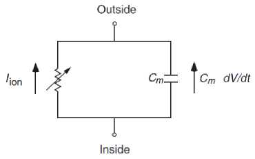
Fig.3. Cell Membrane’s electrical circuit model [12].
Cm ^ + Ih + Is + IZ + Ik + Na = law(1)
where C m is a constant ( μF/cm2) refers to the cell membrane capacitance, I app represents the external applied current. The equation above can be simplified as:
— dy
Cm ^ + чоп Cm ^ + Cm R *app(2)
where Rm and Cm represent the resistance and the capacitance of the cell membrane respectively. Fig. 4 shows the simplest block model to control the human HR by using the improved controller and pacemaker.
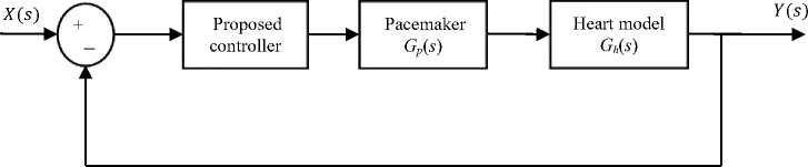
Fig.4. The general block diagram of HR controller with a pacemaker.
The input and output of the block diagram, X ( s ) and Y ( s ) represent the desired and actual heart rate respectively, while Gp ( s ) represents the pacemaker’s transfer function as shown in (3), Since it is considered a low pass system and G h ( s ) denotes the heart transfer function as shown in (4), where the simulated mathematical model of the heart can be designed as an underdamped system of the second order [13].
Gp(s) = -^-
1 (s+8)
Gh(s) =
- 2 +20.8-
-
IV. Model Free Sliding Mode and The Proposed Controller
The MF-SMC solely depends on the input and output data of the controlled plant, and for systems with Single Input Single Output (SISO) this algorithm provides a good performances [14]. For an SISO system, the following approximation can be made:
M ( t ) ~ M ( t ) + U ( t ) - U ( £ -i) (5)
where M represents the system to be controlled, и is the controller output, and ut-1 is the previous value of the controller output [15]. The SMC is a nonlinear controller which is able to control nonlinear, complex and high-order systems under certain and uncertain variation of parameters and external disturbance. The SMC control action is used to force the system’s state trajectory to go towards the sliding surface, then forces the state's trajectory of the system to ''slide" along the switching surface until it reaches the origin [15]. The sliding surface for an SISO system can be defined as:
-
<:■( ;. ■<-- (6)
where Я is the slope of the sliding surface or the bandwidth of the closed loop system, it is constant with a positive value, e (t)= Y (t)- X (t). The main advantages of the SMC control technique are the inherent robustness with respect to matched internal and external uncertainties, and disturbances and the simplicity in both design and [16]. The SMC method is based on Lyapunov’s direct method, which provides a stability analysis approach for nonlinear type systems.
To ensure no movement is allowed of the state trajectories in the state-plane, once the trajectories reach the sliding surface, the derivative of the sliding surface shown in (6) is set to zero, and substituting the approximation of the system model shown in (5) into (6), then solving for the current value of the update control effort, the result is:
U t = ( ^ + A) e(t) - u t-i (7)
The control effort shown above represents the best approximation of the effort, since the system model is imperfect and represents only an approximation as shown in (5). Since the system contains uncertainties, a discontinuous term is added to the control law, in order to drive the system trajectories onto the sliding surface in the presence of modeling error. The control law is then given by [15]:
Ut = -(Ae(t) + e(t)) + ut-1 — к sgn(s) (8)
where k is a positive constant (switching gain) which must be determined, to ensure the stability of the closed-loop system in the Lyapunov sense during the reaching phase, and sgn(s) is the signum function of the sliding surfaces. The control effort yet still suffers from chattering, to eliminate the chattering a time-varying smoothing boundary layer must be applied to the controller form. In order to satisfy this new addition, the term к sgn(s) is replaced by (к — 0) sat(s/0) where “sat” is a saturation function.
The controller effort then becomes:
ut = —(Ae(t) + e(t)) + ut—i — (k — 0) sat (-)
where:
0 = —A0 + к(10)
In this paper, the following form is suggested to modify the control law of (8):
ut = (Ae(t) + e(t)) — ut-1 + к sgn(st-1)(11)
Fig. 5 illustrates the block diagram of the suggested controller with Heart-pacemaker system.
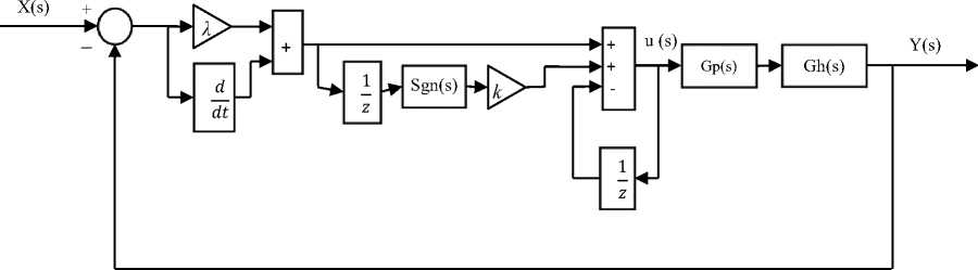
Fig.5. The suggested controller with Heart-pacemaker block diagram.
Although the control signal produces good result, some chattering still exists. To eliminate the chattering, a time- varying smoothing boundary layer must be applied to the controller form, therefore the term к sgn(st-1) is
(—) 0 t-i
replaced by (0 — к) sat
The controller signal of (11) becomes as:
ut = (Ae(t) + e(t)) — ut-1 + (0 — к) sat (^^-1) (12)
The BBO algorithm is used to determine the optimal value for λ and k . Fig. 6 illustrates the block diagram of the suggested controller with Heart-pacemaker system after boundary addition.
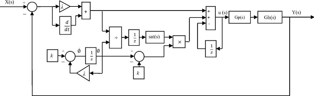
Fig.6. The controller with Heart-pacemaker block diagram after boundary addition.
-
V. BBO Algorithm
BBO is a random optimization method derived from the migration systems in nature, It is developed by D. Simon in 2008 [17]. The BBO algorithm uses a special vocabulary like that in biogeography, where a habitat (island) denotes a candidate solution of the problem, Suitability-Index-Variables (SIV) represent the features of the solution (SIV refers to the number of tuned parameters, in MF-SMC it is λ and k ), and all solutions are evaluated and its quality represent the HabitatSuitability-Index (HSI) which is similar to the fitness or cost in other population-based optimization algorithms [18]. BBO includes two steps: migration (information sharing) and mutation [19].
-
• Migration
The best habitat for living species, is the one with the highest HSI. Therefore, the species migration among habitats happens when the habitats have low HSI or if there are a more species in the high HSI habitats. This operation is called emigration. Immigration occurs when the species go to the habitat of few species and high HSI. Both emigration and immigration of species from/to a habitat, are named migration [20]. Migration process is used to alter a solution Hi by sharing the characteristics from another solution Hj, and can be defined by:
Ht(siv^ H^siVk) (13)
A solution H i may be determined for emigrate or immigrate depending on its emigration rate μ i and immigration rate λ j , which in turn related to the number of species existing in the habitat [18], the rates ( μ and λ ) take a different value in each habitat and are calculated by (14) and (15), respectively.
W = в Ь (14)
^Ф-Э (15)
where I represents the maximum bound of the immigration rate λ, n refers to the population size, ki is the rank of habitat Hi after evaluation, and E represents the maximum bound of emigration rate μ.
-
• Mutation
Mutation is a probabilistic factor used to increase the population diversity, and add new features by modifying one or more of the SIV of a randomly chosen solution, based on its pre-existent existence of P i [17]. (16) shows the probability that the Ith habitat is subject to mutation.
Mi = mmax(1--^) (16)
rmax/ where mmax is the mutation coefficient which is defined by the user, and Pi is the probability of existence of habitat Hi.
The BBO algorithm steps are described by Fig. 7.
-
VI. Simulation Results and Analysis
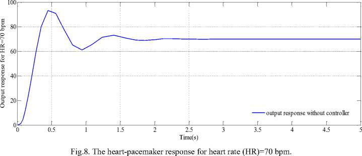
This section presents the simulation results of the heart rate model described in Eq. (4) with the pacemaker in Eq. (3), and the suggested MF-SMC based on the BBO algorithm for the heart rate of 70 bpm (normal adult). The results after adding disturbance are also investigated to improve the performance of the controller. The output response of the heart-pacemaker model without controller are shown in Fig. 8.
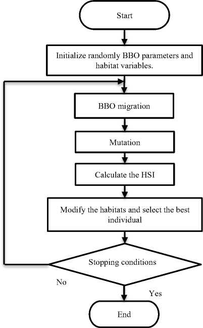
Fig.7. The BBO flowchart.
The BBO algorithm parameters are considered here as in Table 1.
By applying the BBO algorithm, the optimal parameters of the suggested controller with and without disturbance, are listed in Table 2.
Table 1. BBO algorithm parameters.
|
BBO parameters |
value |
|
Number of Generation |
10 |
|
SIV |
2 |
|
n (Population size or Habitats) |
15 |
|
Mutation Probability |
0.06 |
|
E |
1 |
|
I |
1 |
|
Min Domain |
0 |
|
Max Domain |
10 |
Table 2. optimal controller parameters.
|
Controller |
λ |
k |
|
|
Without disturbance |
MF-SMC without boundary |
9.7419 |
9.9039 |
|
MF-SMC with boundary |
9.7861 |
0.29182 |
|
|
With disturbance |
MF-SMC without boundary |
9.0541 |
8.5757 |
|
MF-SMC with boundary |
9.9603 |
2.7247 |
|
Fig.9 shows the Heart-pacemaker response after controller parameters in Table 3. regulated by the suggested controllers according to the
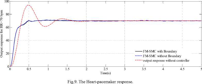
Table 3 addresses the control parameters of simulation results without disturbance.
Table 3. The evaluation parameters of simulation results without disturbance for HR=70 bpm.
|
Controller |
M p % |
t r (sec) |
t s (sec) |
e .s.s |
|
MF-SMC without boundary |
0.0251 |
0.2401 |
0.4354 |
0.25 |
|
MF-SMC with boundary |
0.0128 |
0.244 |
0.455 |
0.0268 |
As noticed from Fig. 9 and Table 3, cardiac system output with MF-SMC with boundary follows the desired heart rate in best and smooth response with small overshoot Mp, study state error (e.s.s), rise time (tr), and settling time (ts), (Mp =0.0128%, e.s.s =0.0268, tr =0.244 sec and ts =0.455 sec), which satisfies the design requirement. While the MF-SMC without boundary also produces a good response, but suffers from small chattering. Fig. 10 illustrates the output response of the controllers after adding (-20) step disturbance in the time (2 sec) to evaluate the robustness of the controller, according to the parameters in Table 3, the controller overcomes the disturbance effectively in both cases.
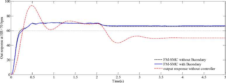
Fig.10. The Heart-pacemaker response with added disturbance.
-
VII. Conclusion
In this paper, two modified Model-Free Sliding Mode Controller MF-SMC scheme is proposed to regulate the heart rate with a pacemaker. BBO algorithm is used here to obtain the optimal parameter's value for the proposed controller, and hence to improve the performance of the HR model with the pacemaker. The different simulation results show that the MF-SMC with boundary gives the best response as compare to MF-SMC without boundary layer. To strengthen the work of the proposed controllers a disturbance was added and the response was fast and perfect in both controllers.
References Design of model free sliding mode controller based on BBO algorithm for heart rate pacemaker
- Y. Okada, Yamashiro, and N. Ohmori, “Mixed Flow Artifial Heart Pump with Axial Self-Bearing Motor,” IEEE/ASME Trans. Mechatronics, Vol.10, pp. 658-665, 2005.
- S. H. Park, and Lee, “Decoupled Control of a Disk-Type Rotor Equipped with a Three-Pole Hybrid Magnetic Bearing,” IEEE/ASME Trans. Mechatronics, Vol. 15, pp. 793-804, 2010.
- K. R. Achu Govind, and R. Aravind Sekhar, “Design of a Novel PID Controller for Cardiac Pacemaker,” International Conference on Advances in Green Energy (ICAGE), IEEE, pp. 17-18 Dec. 2014.
- Jyoti Yadav, Asha Rani, and Girisha Garg, “Intelligent Heart Rate Controller for Cardiac Pacemaker,” International Journal of Computer Applications, vol. 36, No.7, Dec. 2011.
- Z. Jiang, M. Pajic, S. Moarref, R. Alur, and R. Mangharam, “Modeling and verification of a dual chamberimplantable pacemaker,” in Tools and Algorithms for the Construction and Analysis of Systems, pp. 188–203, Springer, 2012.
- Aysan Esgandanian and Sabalan Daneshvar, “A Comparative Study on a Tilt-Integral-Derivative Controller with Proportional-Integral-Derivative Controller for a Pacemaker,” International Journal of Advanced Biotechnology and Research (IJBR), vol. 7, pp. 645-650, April 2016.
- D. Noble, “A modification of the Hodgkin–Huxley equations applicable to Purkinje fiber action and pacemaker potential,” Journal of Physiology. vol. 160, pp. 317–352, 1962.
- R. E. McAllister, D. Noble, and R. W. Tsien, “Reconstruction of the electrical activity of cardiac Purkinje fibers,” Journal of Physiology. vol. 251, pp. 1–59, 1975
- G. W. Beeler, and H. J. Reuter, “Reconstruction of the action potential of ventricular myocardial fibers,” Journal of Physiology. vol. 268, pp. 177–210, 1977.
- Wei Vivien Shi and MengChu Zhou, “Optimal Single-Pulse for Pacemakers Based on a Sinoatrial Model,” IEEE Transactionson Mechatronics, vol. 18, No. 1, February 2013.
- K. Yanagihara, A. Noma, and H. Irisawa, “Reconstruction of sino-atrial node pacemaker potential based on voltage clamp experiments,” Japanese Journal of Physiology. vol. 30, pp. 841–857, 1980.
- J. Keener, and J. Sneyd, Mathematical Physiology, New York: Springer-Verlag, 1998.
- Hari Om Bansal, Rajneesh Kumar, Rohit Kumar Singh and Sachin Bhardwaj, “Design of an Intelligent PD Controller for Artificial Pacemaker,” 2nd International Conference on Power, Control and Embedded Systems, IEEE, 2012.
- Yu Chang, Bin Gao, and Kaiyun Gu, “A Model-Free Adaptive Control to a Blood Pump Based on Heart Rate,” ASAIO Journal, 2011.
- Agamemnon Crassidis and Arielle Mizov, “A Model-Free Control Algorithm Derived Using the Sliding Mode Control Method,” Proceedings of the 2nd International Conference of Control, Dynamic Systems, and Robotics Ottawa, Ontario, Canada, May 7-8, No. 166, 2015.
- Sanjoy Mondal, “Adaptive Second order Sliding Mode Control Strategies for uncertain Systems,” (Thesis), Department of Electronics and Electrical Engineering Indian Institute of Technology Guwahati, INDIA, July, 2012.
- D. Simon, “Biogeography-based optimization,” IEEE Transactions on Evolutionary Computation, December 2008.
- Mohammed Salem and Mohamed Faycal Khelfi, “Application of Biogeography based optimization in tuning a PID controller for nonlinear systems,” IEEE, 2012.
- Haiping Ma, Dan Simon, Patrick Siarry, Zhile Yang, and Minrui Fei, “Biogeography-Based Optimization: A 10-Year Review,” IEEE Transactions on Emerging Topics in Computational Intelligence, Vol. 1, No. 5, OCTOBER 2017.
- R. Kalaivani and P. Lakshmi, “Biogeography-Based Optimization of PID Tuning Parameters for the Vibration Control of Active Suspension System,” CEAI, Vol.16, No.1 pp. 31-39, 2014.
