Designing of Fuzzy Controller to Stabilize Voltage and Frequency Amplitude in a Wind Turbine Equipped with Induction Generator

Author: P. Khani Maghanaki, A. Tahani
Journal: International Journal of Modern Education and Computer Science (IJMECS) @ijmecs
Article in issue: 7 vol.7, 2015.
Free access
The use of wind turbines based on induction generator is very popular to generate electrical power and it has been noted by researchers because of its many advantages compared to conventional methods of electrical energy generation. Factors of uncertainty in the nature of the wind cause variable voltage in amplitude and frequency on the induction generator. It is not appropriate to apply such voltage to the load. So a controller must be designed to be kept constant voltage and frequency. In this paper, a fuzzy controller is used as state feedback to stabilize the voltage, frequency and voltage amplitude. The variable AC voltage generated by generator is converted by rectifier to a variable DC voltage. The variable DC voltage causes a change in the output voltage of the inverter. The PWM switching property is used to stabilize frequency and state feedback is used to stabilize the output voltage amplitude. The obtained error signal with its derivative is applied to the fuzzy controller as input to generate the considered control signal by controller to generate appropriate firing pulses to apply to PWM inverter. Therefore, frequency and amplitude of the output voltage is kept constant with switching control and so maximum power of wind is resulted. Simulation results show that by design the appropriate controller for the considered system output voltage can be stabilized in constant amplitude and frequency.
Wind turbine based on induction generator, voltage and frequency amplitude stabilization, fuzzy controller
Short address: https://sciup.org/15014773
IDR: 15014773
Text of the scientific article Designing of Fuzzy Controller to Stabilize Voltage and Frequency Amplitude in a Wind Turbine Equipped with Induction Generator
Pollution is one of the most important issues in the use of renewable resources which grows increasingly its importance. So that it has forced international organizations like the IEA (International Energy Agency) to take serious decisions to protect the health of the planet and reducing atmospheric pollution [1]. This can be a great help to the serious forecasting to use renewable energy sources. Wind energy is currently the fastest energy from point of view of spread in the world. Today, wind energy is growing at a 30 percent growth in world [2]. In terms of environmental, wind power not only reduces the production of carbon dioxide which is the main cause of greenhouse gas emissions, but it hasn't other pollutions resulting from the use of fossil fuels [3]. In terms of wind power generation costs, these costs are decreasing day by day so that the cost of each KWh power generated by wind turbine had decreased 20 percent during 5 years. Also in terms of size wind turbines come to market with higher powers while these turbines have an output of 5 MW [4]. The use of wind power plants with variable speed has advantages compared to the fixed speed wind power plants. Although wind power plants with a constant velocity, can be connected directly to the network, however, a wider range of energies is covered by the variable speed wind power plants and has less mechanical stress and noise. Today, with advances in power electronics, all speeds control is possible and effective [5]. In turbines with variable speed, in fact, the rotary part of turbine absorbs the mechanical power fluctuations with changes in its speed and output power curve is flatter [6-7]. This can help to improve the quality of power. However, wind is a variable quantity and every moment is changing. So the voltage amplitude and output frequency of the wind turbine is changing that variable voltage is not suitable for consumer. So a controller must be designed to be capable to deliver maximum voltage and power with constant amplitude to consumer from turbine. In last research in frequency and voltage control of wind farm based on induction generators the simple proportional -integral controller (PI) is applied that the PI controller parameters can be adjusted by trial and error method. PI controllers have a gain with fixed values. Hence against the wide variation of operating conditions and non-linear factors, are not suitable to dynamic performance. Furthermore, the fuzzy controller based on fuzzy logic is one proper approach to control the power system stability So that the controllers are able to adapt themselves to the conditions of the system.
In this paper, the fuzzy controller is designed to maintain the amplitude and frequency of available voltage caused by the uncertainty of nature wind.
-
II. Studied System
The studied system consists of a wind turbine is connected to the load as shown in Figure 1.The system as shown as in Figure 2, includes a wind turbine, induction generator, diode bridge rectifier, filter DC, inverter and suitable AC filter.
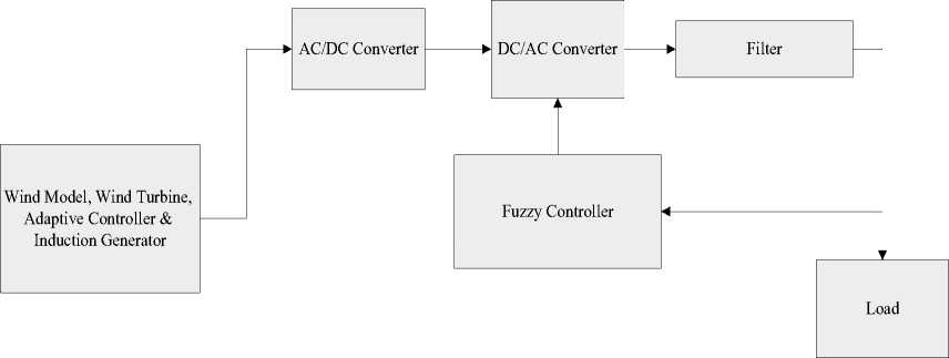
Fig.1. Overview of a Wind Turbine Connected to the Load
Fig. 2 shows a general view of a wind turbine block, the adaptive controller and the induction generator. Figure 2 refers to relation between wind model, controller, adaptive calculation and induction generator modeling.
м
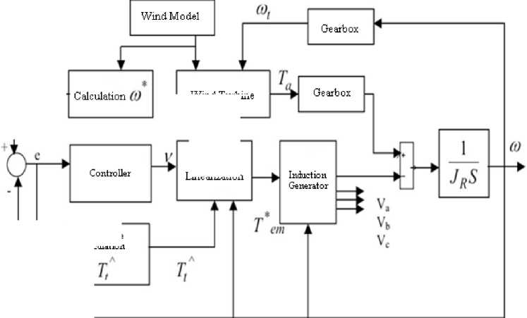
Fig.2. A general view of a wind turbine block, the adaptive controller and the induction generator
Adaptive Calculation
Wind Turbine
Feedback
Line arization
-
A. Wind Turbine
Torque produced by the wind turbine with no losses is as follows [8-9]:
Ta = 1πρCt(λ)R3V2
λ= Rω(2)
V
C
C = p(2)
tλ
Where R is the radius of the wind turbine, ω is the turbine rotation speed and λ is the ratio of tip speed to the wind linear speed.
-
B. Adaptive Controller as Feed Forward
Due to changes in the parameters in studied system, using the fixed gain classic controllers is not reasonably fixed. Because this controller is not capable to maintain system stability in conditions of parameters variation. To solve this problem, the adaptive controller can be used. Therefore, this controller is used in wind farm. The overall block diagram of the adaptive controller is shown in Fig. 3. In this Figure the calculation of turbine rotation speed and adaptive calculation of T ^ is presented.
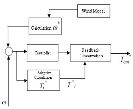
Fig.3. The overall block diagram of the adaptive controller
e = — ke
JR
~

From the above equations, the result is the following adaptation law:
Tt = Ye t JR
Y is a constant value that is considered 2000000. So the
J is defined as follows:
J
R
A2 l-l Jt + J m
(V n J
J
-
C. Calculation of to *
to * is obtained from following equation [9]:
to * = n - op^ V (4)
mR
In the above equation n=98 and R= 33 is the turbine radius and model of to is considered as a gain in wind speed.
-
D. Controller
The equation of the controller is considered as follows:
v = to * + ke (5)
The value of Ke is 1.8 in the above equation.
-
E. Adaptive Computing of T ˆ
According to the adaption law, we have [9]:
e ( t ) = H ( s ) [ k ф T ( t ) v ( t ) ] (6)
In the above equation e (t) is a scalar quantity, H(s) is the real transfer function, k is the constant with given sign, ф is the 1 *M vector function of time and V(t) is the measurable vector of 1*M. If ф is changed as follows:
ф ( t ) = — sgn( k ) Y ev (t ) (7)
With the constant and positive у , the e(t) and ф are bounded. If V is bounded, so:
e ( t ) —> 0 as t —— да (8)
Now with the last equation for the dynamic error, we have following equations:
In the above equation:
JT = 2.15 X 10 6 Kgm ’1
J M = 63.87 Kgm2 n = 98
F. Feedback Linearization (T em* Calculation)
A torque which is estimated by an adaptive controller for generator and is applied as input to it, is obtained by following equation [9]:
T em
= JR

G. Simulated Adaptive Controller Model
Given the above steps, adaptive controller simulation model is presented in Fig. 4. In Figure 4, adaptive control equations and mathematical modeling related to its inputs are presented.
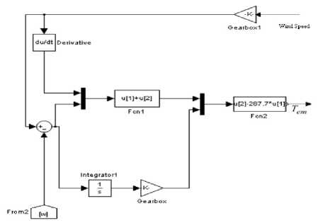
Fig.4. Simulated adaptive controller
H. Induction generator
The Park transform is used in induction generator model. In this transform of three-dimensional space (a-b-c) is transformed to the (d-q-0).Generator input equations has become to its new form by Park transform. Blocks and new equations are as following. Also the outputs are (a-b-c) by the inverse Park transform [10-13].
Equations of induction generator are as follows [1013]:
i qs
ids
v ds = r s i ds
^-
to^ qs
d
+— л
dt
ds
iqr
vqs
= r i rs qs
+ to^ds
d
+— л
dt
qs
i dr
v 0 s
= ri s os
d
+— л
dt
os
V mq
vdr
= r r i dr
^
(to - tor )Xqr + — Xdr dt
v qr
= г г r qr
+ (to
—
tor )^dr +
d
dt
^ qr
V qs
^-
V mq
xls
= Vds
V' q r
V md
xls
V mq
X l r
_ Vdr — Vmd
f x-r
(VL V xM( + , )
xls
xlr
7 Vds V drX
Vmd = xM (-ds + d^T")
xls
xlr
T em
3 P
v0r
= r r i 0 r
d
2 2 to b
( V djqs
V qs l ds )
T em
•
X ds
•
Л
•
л
•
л
+ —^0 r
3P
= 4 J
L r R s
L a
to
L m R r
L a
L a
dt
to r
to b
2 H
( T e
T L )
—
\qsids )
qs to
L r R s
L m R r
L a
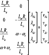
I. Block Circuits of d and q Axis
V s = to b И
v — qs
to r /- Vds + ~ (Vq to
xls
— V qs » dt
The block of the q axis and inside of the q axis block is shown by Fig. 5. The block of the d axis and inside of the d axis block is shown by Fig 6.
-
J. The Bock Circuit of The Rotor and abc to dqo Transform
The inside of rotor blocks abc to dq0 transform include mathematical modeling of induction generator and system is shown by Figures 7 and 8.
-
K. App ying Fi ters
AC/DC and DC/AC converters create harmonics from AC and DC side that may have no suitable size for the source or load. The filters are used to reduce the harmonics. Filter that is used in the AC side are to reduce the current harmonics and on either side of the DC is to reduce the voltage harmonics amplitude.
r I
Vds = tob ^ vds + —Vqs + — (Vmd — Vds ) ^ dt
J I tob xs
V os = to b J ( v os — rslos ) d t (23)
I If to tor\ I , r - / f\|j
V qr = to b ^ v qr — (----- ^ ) V dr + T (V mq - V - r ) ^ dt
J [ tob xr
III. The Fuzzy Controller Design
The fuzzy controller uses the fuzzy logic rules to obtain control applications. Fuzzy rules have been established based on control rules. Fuzzy logic systems are not designed based on mathematical models. Fuzzy controllers implement the human logic using fuzzy logic that is planned by membership functions, fuzzy rules and membership rules [14-15].
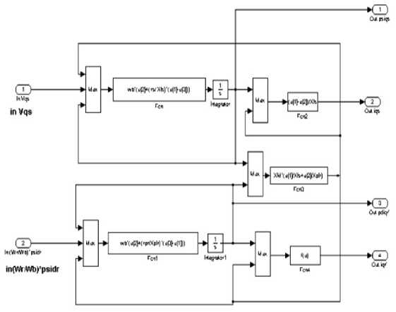
Fig.5. Inside the q axis
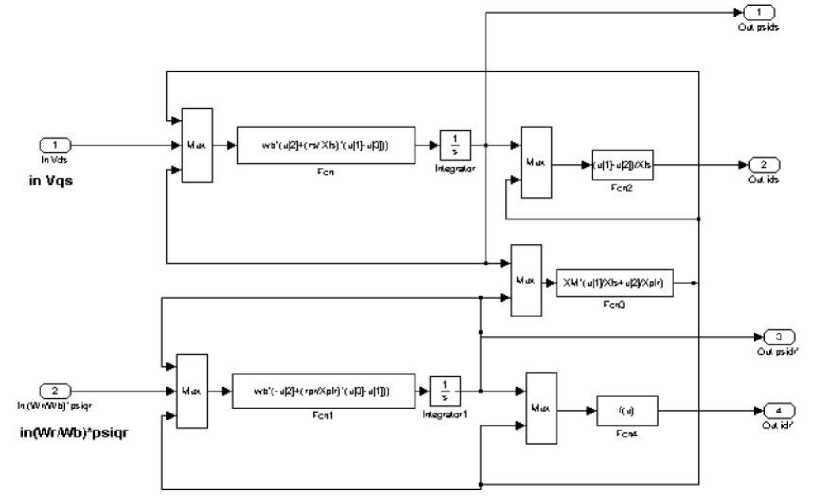
Fig.6. Inside the d axis
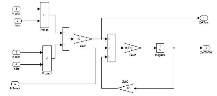
Fig.7. Inside the rotor block
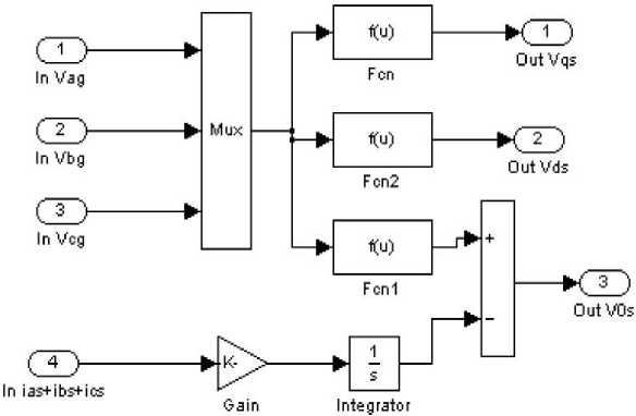
Fig.8. Inside the abc to dqo transform block
In this study, the output voltage is sampled and is compared with the reference voltage level and the generated error signal and its derivative is applied to the controller as the controller inputs.
A fuzzy system is described by a set of IF-THEN rules and uses a number to define the degree of membership in its membership functions. To solve the problem in fuzzy controller, controller inputs, error signal and its derivation, and its output are considered as the control signal. The wind turbine system with fuzzy controller structure is shown in Fig. 9.
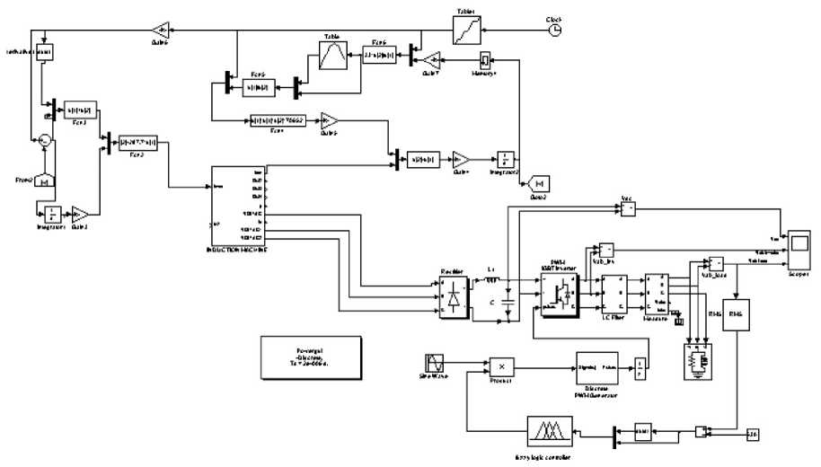
Fig.9. The Proposed fuzzy type-1 controller in wind turbine system.
Design of fuzzy controller has 4 steps that are presented as follows [16-18]:
Step 1. Determination of the system dynamic behavior and characteristics
In this step, the controller input and output variables and their variations range considering load-frequency control problem should be determined. Input signals are considered to create the base rules as the IF part and the output signal of the fuzzy controller are considered as the THEN part.
Step 2. Determination of the fuzzy sets and membership functions
In this step, the degree of fuzzy membership functions related to each input and output signals are determined and the fuzzification processing is completed.
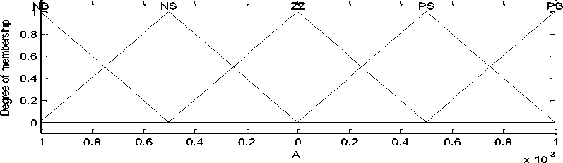
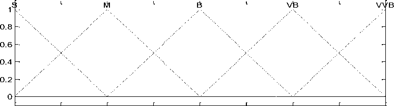
The fuzzy controller membership functions are shown in Fig. 10.
5 10
20 K
30 35 40
Fig.10. The membership functions of proposed fuzzy controller (A: input and K: output)
Step 3. Description of inference engine
In this step, fuzzy rules are formed by the control rules that system performance is based on that rules.
Step 4. Formation of the defuzzification process
The fuzzy rules are combined and defuzzification process is performed on the output and output of the fuzzy inference engine.
In this study the membership functions inputs and output are considered same. For inputs and output, the 5-segments triangular membership functions are applied. Each input has five membership functions, so the number of base fuzzy rules is 25. The fuzzy rules of fuzzy controller are presented in Table 1. fuzzy rules refer to conception of fuzzy controller inputs and relation of input signals error and its derivation.
Table 1. Fuzzy rules of proposed fuzzy type-1 controller
|
ec |
|||||
|
e |
NB |
NS |
ZZ |
PS |
PB |
|
NB |
S |
S |
M |
M |
B |
|
NS |
S |
M |
M |
B |
VB |
|
ZZ |
M |
M |
B |
VB |
VB |
|
PS |
M |
M |
VB |
VB |
VVB |
|
PB |
B |
VB |
VB |
VVB |
VVB |
-
IV. Simulation and Results
The studied system data related to the induction generator is presented by Table 2 [19].
Table 2. Simulation parameters [19]
|
Parameter |
Value |
|
Rated Power |
1.6 MVA |
|
Line to line voltage |
33 KV |
|
R S |
36 Ω |
|
R r |
28 Ω |
|
X S |
4 Ω |
|
X r |
4 Ω |
|
X m |
53.35 Ω |
|
Poles Number |
4 |
Overview of system simulated in Simulink is shown in Fig. 12. In this section, a three phase fault is applied to the system according to Fig. 12 and with design of fuzzy controller is attempting to fix and maintain the voltage and frequency fluctuations.
Fig.12. Overview of the simulated system
Input voltage curves of the studied system is presented in Fig. 13. Rectifier and inverter output curves are shown in Figs. 14 and 15, respectively. Total harmonic disorder (THD) of inverter output voltage is shown in Fig 16.
System Input Voltage
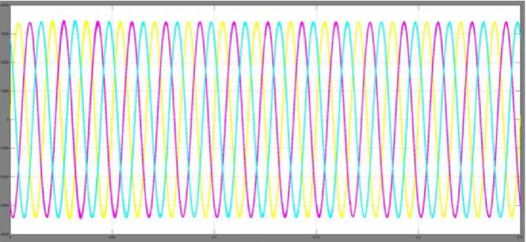
Time tsi
Fig.13. Input voltage curve of system
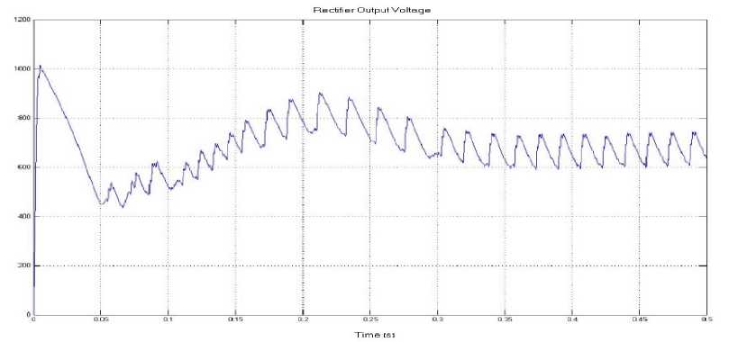
Fig.14. The output voltage of the rectifier
Inverter Output Voltage
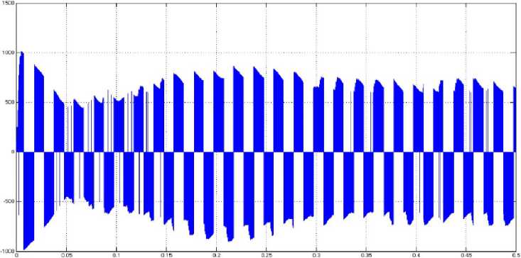
Time tsi
Fig.15. The output voltage of the inverter
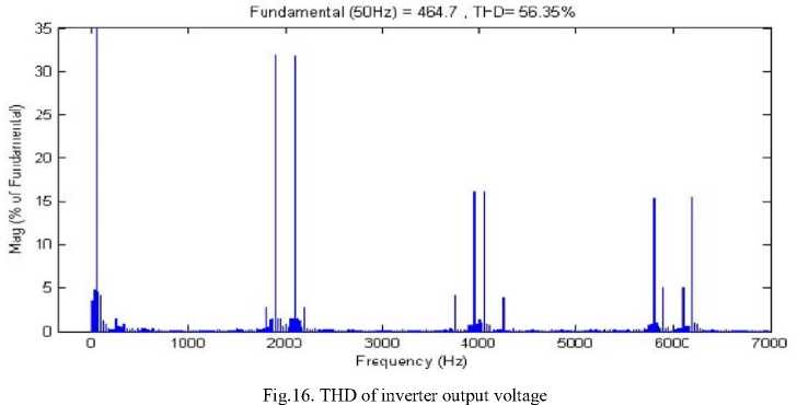
Output voltage curve of the studied system is presented in Figure 17. As shown as in Fig. 17, output voltage of system is sinusoidal. The THD of system output voltage is shown in Fig. 18. THD of system output voltage in this stage is 4.65 percent ant it is within standard ranges. THD of system output voltage based on step R-L load is shown in Fig 19. THD in this condition is equal to 4.91 percent in standard range. So the total harmonic distortion of system is in standard domain. The results showed that fuzzy controller in power system stability are robust and suitable for damping application in power system. According to obtained results the amplitude of frequency and voltage oscillations are kept constant and in standard range by fuzzy controller application.
System Output Voltage
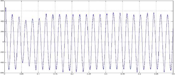
Fig.17. Output voltage curve of the studied system
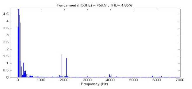
Fig.18. THD of system output voltage with fuzzy controller.
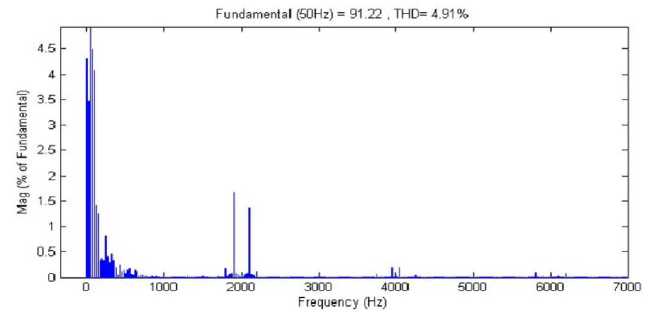
Fig.19. THD of system output voltage based on R-L input load with fuzzy controller.
-
V. Conclusion
In this paper, a fuzzy controller is designed for stabilization of the amplitude and frequency of the variable voltage caused by the uncertainty of the wind nature. A fuzzy adaptive controller was designed as direct supply to use maximum wind power at each moment. As is clear from the results, by applying the error associated with changes in wind speed, Adaptive fuzzy controller employs wind maximum power and then voltage was created in induction generator. Induced voltage has variable frequency and amplitude which were kept constant in amplitude and frequency by fuzzy controller and power electronics circuits. According to the results output voltage is within the standard in point of view of total harmonic disorder.
References Designing of Fuzzy Controller to Stabilize Voltage and Frequency Amplitude in a Wind Turbine Equipped with Induction Generator
- M.R. Dubios, "Review Of Elementromechanical Conversion in Wind Turbine", Report EPP00, April 2000.
- S. Muller, M. Deicke, and R. W. De Doncker, "Doubly fed induction generator systems for wind turbines," IEEE Ind. Appl. Mag., vol. 8, no. 3, pp. 26–33, May/Jun. 2002.
- M. Liserre, R. Cardenas, M. Molinas, and J. Rodriguez, "Overview of multi-MW wind turbines and wind parks," IEEE Trans. Ind. Electron., vol. 58, no. 4, pp. 1081–1095, Apr. 2011.
- A. Petersson, L.Harnefors, and T. Thiringer, "Evaluation of current control methods for wind turbines using doubly-fed induction machines," IEEE Trans. Power Electron., vol. 20, no. 1, pp. 227–235, Jan. 2005.
- R. Pena, J. C. Clare, and G. M. Asher, "Doubly fed induction generator using back-to-back PWM converter and is application to variable-speed wind–energy generation," Proc. IEE B Electr. Power Appl., vol. 143, no. 3, pp. 231–241, May 1996.
- J.T.G Pierik, A.T.Veltman, S.Haan, G.A.Smith, "A New Class of Converter for Variable Speed Wind Turbine", EWEC, 1994.
- J. G. Slootweg, S. W. H. de Haan, H. Polinder, and W. L. Kling, "Modeling wind Turbines in power system dynamic simulations," in Proc. IEEE Power Engineering Society Summer Meeting, Vancouver, Canada, , pp. 15-19, July 2001.
- R.M.Hilloowala, A.M.Sharaf, "Modelling, Simulation and Analysis Of Variable Speed Constant Frequency Wind Energy Conversion Shame Using Self Excited Induction Generator" IEEE Conf.1991.
- G.Raina and O.Malik, "Wind Energy Conversion Using a Self-Excited Induction Generator", IEEE Tans. PAS, Vol.102, 1983.
- J. Hu and Y. He, "Dynamic modeling and robust current control of wind- turbine used DFIG during AC voltage dip," J. Zhejiang Univ. Sci. A, vol. 7, no. 10, pp. 1757–1764, Oct. 2006.
- F. Zhou, G. Joos, C. Abbey, L. Jiao, B. Ooi, "Use of Large Capacity SMES to Improve the Power Quality and Stability of Wind Farms", Power Engineering Society General Meeting, 2004. IEEE, 6-10 June 2004 Page(s):2025 - 2030 Vol.2, 2004.
- L.H. Hansen, L. Helle, F. Blaabjerg, E. Ritchie, S. Munk-Nielsen, H. Bidner, P. Sorensen and B. Bak-Jensen: Conceptual Survey of Generators and Power Electronics for Wind Turbines, Riso-R-1205 (EN), December 2001.
- J. G. Slootweg, S. W. H. de Haan, H. Polinder, and W. L. Kling, "Modeling wind Turbines in power system dynamic simulations," in Proc. IEEE Power Engineering Society Summer Meeting, Vancouver, Canada, pp. 15-19, July 2001.
- Z.Chen, S.Arnalte, M.MC.Cormick, "A Fuzzy Logic Controlled Power Electronic System for Variable Speed Wind Energy Conversion System", IEEE Sept.2000.
- B.HAMANE, M. L. DOUMBIA, M. BOUHAMIDA and M. BENGHANEM, "Control of Wind Turbine Based on DFIG Using Fuzzy-PI and Sliding Mode Controllers", Ninth International Conference on Ecological Vehicles and Renewable Energies (EVER), 2014.
- Zadeh, L.A., "Fuzzy Logic," Computer, Vol. 1, No. 4, pp. 83-93, 1988.
- Yevgeniy V. Bodyanskiy, Oleksii K. Tyshchenko, Anastasiia O. Deineko, "An Evolving Neuro-Fuzzy System with Online Learning/Self-learning", International Journal of Modern Education and Computer Science, vol 2(8), PP.1-7, 2015.
- Essam Al Daoud, "An Efficient Algorithm for Finding a Fuzzy Rough Set Reduct Using an Improved Harmony Search" International Journal of Modern Education and Computer Science, vol 2(8), PP.16-23, 2015.
- J.G. Slootweg, S.W.H. de Haan, H. Polindar, W.L. Kling, "General Model for Representing Variable Speed Wind Turbine in Power System Dynamics Simulations", IEEE Trans. Power Sys., 18, (1), pp. 144-151, 2003.
