Determination of microrelief of the sample by singular beams superposition

Author: Sokolenko Bogdan V., Shostka Natalia V., Karakchieva Olga S., Volyar Alexander V., Poletayev Dmitrii A.
Journal: Компьютерная оптика @computer-optics
Section: Дифракционная оптика, оптические технологии
Article in issue: 5 т.43, 2019.
Free access
In present paper we propose easy way to implement method of interfering vortices with opposite topological charge for the real time determination of the thickness and information about the surface of studied samples with the resolution up to 7 nanometers. The determination of the characteristics of the medial cross-section of submicron-objects becomes possible due to phase sensitivity of interfering singular beams to the slightest changes in the optical path difference between them. The dependence of rotational angle of resulting interference pattern in case of different sample thickness for two singular beams superposition is considered in detail.
Optical vortex, phase, optical microscopy, singular beams, surface relief detection
Short address: https://sciup.org/140246507
IDR: 140246507 | DOI: 10.18287/2412-6179-2019-43-5-741-746
Text of the scientific article Determination of microrelief of the sample by singular beams superposition
Intensive developing of nanotechnologies in electronics, engineering, biology and biomedicine needs new techniques for fast, low-error and easy in realization measurements and increasing the resolution of existing methods of optical microscopy. Thus, in order to meet the new needs of applied sciences a large number of recent publications in the field of modern optics were devoted to the problem of beam reflection or its propagation through the studied samples for both: coherent and non – coherent light sources [1–3] in order to develop methods for noncontact study of micro- and nanostructures in material processing as well as biomedical applications [4].
One of the most common principles of optical microscopy – scanning probe microscopy, is an area of microscopy in which the image of the object surface formed by a probe scanning its surface. The image obtained by mechanically moving the probe along a path in the form of a raster (line by line) and registering the interaction between the probe and the surface as a function of its position. This type of microscopy includes Scanning Near-field Optical Microscopy (SNOM), Atomic Force Microscopy (AFM), and Scanning Tunneling Microscopy (STM) and vide range of Fluorescence Microscopy modifications [5–8].
Furthermore, Stimulated Emission Depletion Microscopy (STED), a type of fluorescence microscopy that achieves a resolution in excess of the diffraction limit by selective fluorescence quenching, can be distinguished [9]. An important advantage of STED microscopy is that the resolution improvement achieved in real time and usually does not require long-term data processing. Also, a newest application of “doughnut” beam carrying tightly focused optical vortex by high numerically aperture objective was implemented in STED microscopy [4, 8–11].
Optical methods of surface analysis, which use an interferometry and coherent light sources, have many advantages, including non-contact and non-destructive interaction with the test sample [12, 13], high resolution [14], etc. The main difficulties of such method are high sensitivity to vibration and speckle noise. The salvation of peculiarities mentioned above leaded to the searching of methods based on using of Bessel and Laguerre-Gaussian beams. [15, 16] where the dependence of rotation angle for intensity distribution of so-called “two-lobed fields” were investigated in dependence on the depth of focus for spiral beams as well as influence of amplitude and phase distortions on the formation of the light field with the intensity rotation was established. [17]. Thereby, in latest research [18] authors proposed a new concept of full-field topographic microscopy based on array of self-interfered optical vortices enabling a reference-free displacement and 3D shape measurement of reflective samples due to a very high rotation sensitivity to defocusing which can be applied to an accurate depth estimation in conventional optical microscope [19, 20]. Another method named Optical Vortex Scanning Microscope for visualization and analysis of nanometer structures, where the sample is scanned by a moving vortex, was demonstrated in work [12]. Hence, the way of investigations the surface roughness and the thickness of the sample were demonstrated in work [21] by analyzing interference patterns in the form of a vortex spiral. The interference patters between reference beam and object vortex beam passing through the sample demonstrates rotation depending on surface parameters of the sample. In contrast to [17–19] probe beam contain single charged optical vortex which interfered with Gaussian beam and rotation of interference pattern analogues to “two-lobed fields” allow to define surface height difference by angular orientation. The method has shown good results due to the high sensitivity of singular beam phase to the small distortions of the wave front caused be the sample. However, one of the significant drawbacks should be indicated as the complexity of the determination the rotation of the interference spiral with sufficient accuracy.
In this paper, we propose an optical scheme of investigation of the sample profile with nanoscale resolution based on the analysis of evolution of the interference pattern of two superimposed vortices with single topological charges and opposite signs. This method is suitable for the real time determination of the thickness and information of surface of studied samples. The determination of the characteristics of the medial cross-section of submicron-objects becomes possible due to phase sensitivity of the singular beam to the slightest changes in the wave field. The dependence of the angle of rotation of the resulting interference pattern of two singular beams on the sample thickness is considered in detail.
1. Theoretical basis
The phase and propagation characteristics of Laguerre– Gaussian (LG) beam are of great current research interest and found an application in various optical devices for trapping, moving and angular orientation of microparticles in combination with Bessel beams as well [22–31]. The last significant achievements in the research were implemented in relation to the practical application of the LG beams, in particular, in microscopy. A large number of publications in recent years are devoted to the problem of beam reflection or its propagation through the studied samples for coherent and non-coherent light sources in order to develop metrological methods for non-contact study of nanostructures. These principles can be used for investigation the surface profile of samples of different nature with high resolution [11–18]. Summarizing, Laguerre–Gaussian beams carrying low-order optical vortex is the most convenient as a probe beam for development of phase retrieval methods in application to metrology of optically transparent and reflecting samples, which may have not only sophisticated surface relief but also internal structural inhomogeneity.
Laguerre–Gaussian beam is the solution of the wave equation with radial symmetry of the intensity distribution. The simplest type of Laguerre–Gaussian beams is an optical vortex (when the radial index is zero) possessing a phase singularity and characterized by the preservation of the zero intensity on the phase uncertainty line in the paraxial beam, as well as the ability to transfer its own orbital angular momentum.
A particular solution of the paraxial wave equation for the LG beam can be written as follows:
ro 0 (42r w I w
l Lm
• exp ( - il ф ) х
x exp
ikr 2
2 z (1 + zR/z 2)
x exp (i(2m + l -1) arctan (z/zR )) • exp(-ikz), where zR = kto 0/2 determines the Rayleigh length, too -beam waist in the plane of incidence on the surface of the sample z = 0, l = ±1 - topological index, w = to0^1 + (z/zR )2 - current beam waist, ф = arg(x + iy) -azimuthal angle, r = x2 + y2 , k=n • (2л / X)- wave number in the medium with refractive index n.
Thus, the main parameters affecting the quality of measurement are waist radius, A z - geometrical path difference, Аф - phase difference caused by various thickness of explored sample and n – refractivity index for transparent materials. We restrict ourselves on linearly polarized paraxial Laguerre–Gaussian beams with cylindrical symmetry to avoid undesirable intensity downturn and structural instability [32]. As it was found by numerical simulation and confirmed experimentally in [33], the spreading of low-order Laguerre–Gauss beams carrying optical vortex through a random distorting medium experiencing a minimal structural deformation, thus choosing of vortex with topological charge l = ± 1 is practically justified.
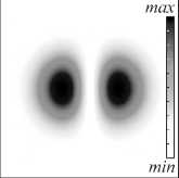
As shown in the paper [34] interference of two Laguerre–Gaussian beams carrying equal but opposite topological charge resembles two slices of maximum intensity, separated by a thin dark band corresponding to the minimum intensity.
Computer models of the transverse intensity and phase distributions in the singular beams, as well as the result of their interference, are presented in Fig. 1.
Phase images can be considered as a two-dimensional phase distribution or as an optical path difference of interfering rays. For visualization of optically inhomogeneous transparent media, it is known that the dependence of the optical path difference is proportional to the local projection of the refractive index on the beam direction:
h ( x , y ) =
Хф ( x,y ) 1
4 n n ( x,y,z )
where X - the wavelength of the incident wave.
The main task is to analyze the dynamics of the recorded intensity when the phase difference of the interacting beams changes. When the optical paths of two beams in the arms of the interferometer are close, the interfering waves have the same radius of the beam waist to 0 and the curvature of the wave front. Only in this case we may obtain symmetrical intensity distribution of superposed singular beams.
The method of determining the angle of rotation for the interference pattern is quite simple. The program determines the center of the dark band between two slices of maximum intensity, through which a line is drawn as shown in Fig. 2, with respect to which the rotation of the similarly constructed line of the following interference pattern is determined when the optical path difference of the interfering beams changes, corresponding to the elevation of the sample.
Thus, the analysis of the changes in the obtained interference patterns allows us to extract information about the phase shift between the superimposed beams and the state of surface roughness and thickness of the sample, as well as the problem of optimizing such procedures in practice.
In practice, it is possible to use two types of measurement schemes: when the singular beam is a probing beam and when the vortex is introduced into the reference beam. In both cases, the interference patterns are the same, but the direction of their rotation will be inverted.
(a)
(d)
(b)
(e)
(c)
(f)
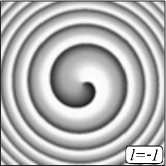
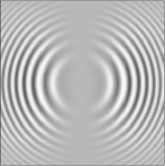
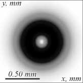
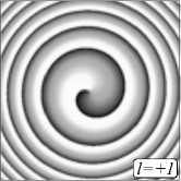
Fig. 1. Numerical model of LG beams superposition with opposite topological signs: (a) intensity distribution (inverted) of LG beam with unit positive topological charge and opposite one (b) respectively; (c) and (d) – the pairs of phase maps corresponds to the phase patterns of optical vortices (LG beams with zero radial index) and opposite topological charges; (e) is the resulting pattern of superposition of two LG beams of equal and opposite by the sign topological charges and (f) corresponds to the phase portrait of interfered singular beams.
Parameters of superimposed beams were the following: ω 0 = 180 µ m, n = 1.00, z = 1 m, λ = 632.8 nm
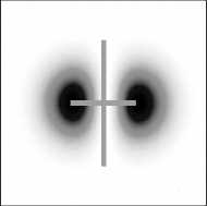
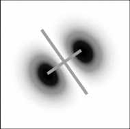
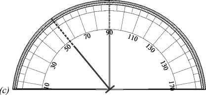
Fig. 2. Interference patterns (inverted) of pair (a) and (b) neighboring positions with Δ = 128.0 nm. The angle between symmetry axes 36,5° is well observed after digital processing (c)
2. Phase-shift retrievals for transparent threads: an experiment
Due to its high sensitivity to wave front inhomogeneity, caused by geometry of the sample, optical vortices and their interference was adopted to surface roughness analysis and curvature imaging of reflecting surfaces [2, 21]. Nevertheless, transparent samples with complex relief of boundary surface may have an inhomogeneity of refractivity index. Both these parameters define the overall optical path difference between object and reference beams. From this point of view, such samples are amplitudephase objects. The simplest way for fast and computa-tionally-non-intensive analysis of such objects should be used in form of direct data acquisition from image sensors and cameras with minimal adjustments and transformations. For this purpose, a superposition of a high-sensitivity probe beam carrying optical vortex with a reference beam also containing a singularity with the opposite sign was used. To estimate the sensitivity of two-singular beams interference method we restrict ourselves on consideration only homogeneous isotropic media as, for example, thin cover slip. Typical cover slip has 250 μm thickness and high quality of parallelism. In case, when the singular beam slide on the isotropic plate with a gradient surface profile, we can choose an arbitrary posi- tion and set it as starting point, thus all the next measurements will be written relatively to the value of phaseshift at this point in terms of angular turn of intensity pattern. This effect becomes the basis for a high-resolution microscope device, where rotational process may be easily captured experimentally and processed automatically in real time.
Typical experimental set-up for two-beam interference includes vortex beam shaping unit and interferometer with almost equal distances in object and reference arms to avoid beam waists misalignment. The scheme, proposed in Fig. 3c, allow to control test object position and very optical path difference between the beams. The light beam from the He-Ne laser is converted into the single-charged vortex beam by computer generated hologram H with “fork”-shape amplitude produced by photographic method [35–37]. The first diffraction order was cut by the diaphragm D and five-times expanded with telescope T. Next the telescope T beam splitter BS1 splits the initial vortex beam with topological charge l =+1 to the object and reference beams, the reference beam has opposite sign of charge l =–1 for receiving of appropriate interference pattern on the CCD camera. Microscope objectives MO1 and MO2 10× with numerical aperture 0,30 focused the beam on the sample surface and project the light on camera matrix. Both microscope objectives adjusted so that to receive parallel light beam after the sample without scale transformation. Taking into account that polarization state has greatest influence to the longitudinal component of the electric vector of the light field, thus the greatest visual difference in the intensity picture is observed when using the first-order vortex, which was demonstrated in [38, 39].
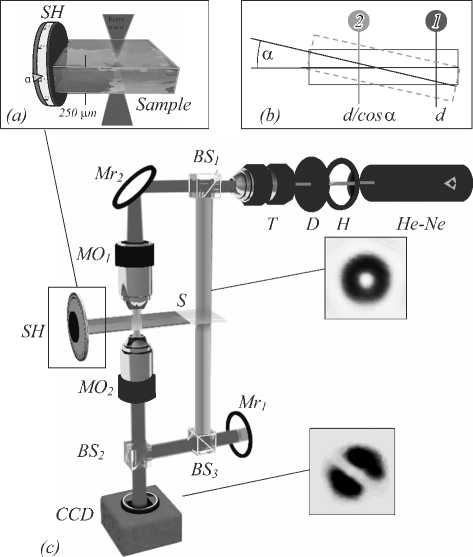
Fig. 3. Schematic representation and the principle of thickness measurement for transparent object: (a) rotational sample holder SH with the cover slip S of thickness d = 250 μm;
(b) principle of metering, where two measurements were token: first one “1”, when slip was placed strictly horizontally and the second one “2” with tiny inclination ( a = 0 x 5 ° controlled with sample holder SH; (c) optical configuration of experimental set-up: the Gaussian beam emitted from He-Ne laser converted into the Laguerre-Gaussian, which is carrying optical vortex with computer synthesized hologram H and filtered by diaphragm D after what the first diffraction order with topological charge l = +1 was separated and 5 x expanded by telescope T. The Mach–Zehnder interferometer was built on pairs of beam splitters BS 1 and BS 3 and mirrors Mr 1 , Mr 2 . An extra beam splitter Bs 2 in the reference beam serves for inversion of optical vortex topological charge to opposite one on the exit from interferometer (l = –1). Microobjectives MO 1 and MO 2 focus the beam on the sample surface and project the light on CCD camera and stored
Such wise, we choose focusing conditions for operating in paraxial regime, where longitudinal components of electric field and their contribution to the intensity pattern may be neglected. The length of interferometer arms is 500 mm and was chosen equal as possible, the mirror Mr 1 was inserted for realization of even number of reference beam reflections and keeping opposite sign of topological charge. Other distances between optical elements are not critical, so the setup scheme may be easily transformed for measurement of reflecting samples.
Slightly inclined test sample makes possible to control the effective optical thickness, which causes on phase shift between the beams. This process is observed visually by turn of interference pattern, as shown in Fig. 4. Stabilization of interference pattern was reached by synchronization of probe beam and reference one with the sample itself. Such principle allow avoiding instability of interference pattern caused by random movement and shudder. Moreover, proposed method is resistible against the aberrations of optical elements since only central part of the beam carrying necessary information about vortex phase.
Fig. 4 shows the dynamics of interference pattern for different values of optical path difference. The intensity minima correspond to unfolded phase profile of superimposed beam and may be easily recognized with computer vision procedures. The geometrical thickness of the sample under test is defined as optical path difference divided by refractivity index n of glass, where n = 1.5168.
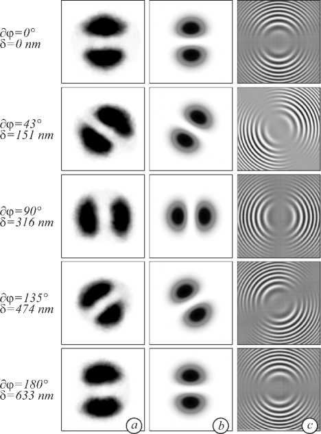
Fig. 4. The evolution of superposition of vortex beams with opposite signs of topological charge for different optical path differences z+ S . (a) Experimental patterns (inverted) and (b) corresponds to computer simulation of intensity distribution (inverted), (c) shows the evolution the phase of resulting field Im E(r, ф )
An estimation of sensitivity for turn of superposition pattern indicates that the resolvable threshold for determining the rotation angle of the pattern is 3° for current state of the experimental set-up. One full turn occur, when optical path difference acquires the value of a multiple of the wavelength X, for He-Ne laser (X = 632.8 nm) the vertical resolution is 5 = 10.54 nm. In dependence of media refractivity index n * 1, the total resolution for physical thickness measurement may be expressed as 5geom= 10.54/n and reaches for glass material (BK-7) with n = 1.5168 5geom = 6.95 nm.
The total phase shift observed by the angular rotation of the interference spiral was calculated using simple expressions: дф = 0 + 2 л , m X = n ( d 1 - d 2) = nh , where d 1 – d 2 – is the height difference between two adjacent levels of the sample surface (geometric path), mX - the optical path difference with multiply factor m and дф - is the phase-shift caused by difference in thickness. A complete depth map can be compiled by step-by-step scanning in the xy plane by the sample holder transverse movement, so that a sample may be examined and imaged without limitations to linear dimensions.
Conclusion
Development of new methods for phase shift analysis in application to thickness measurement is the quite important issue in fundamental and applied research in optical noninvasive metrology. A great attention paid to the development of optical methods is caused, first of all, by the fact that in field of applicable measurement technics in nanoresearch and the nano-systems industry is not limited from the point of view of image quality improving, but also has great importance for such tasks as recording information in the optical environment, lithography, nano-structuring and optical manipulation. In particular, great attention was attracted by the possibility of using interferometric methods for investigating stepped structures in industry and, as result, may be applied to interdisciplinary research as biophotonics and medicine.
This research presents the results of theoretical analysis, simulation and experiment, the sensitivity of singular beams to external perturbations is determined. It is shown that a discernable rotation of intensity profile arises during the changes of sample thickness with step of 6.95 nm. The proposed technology is used in the microscopy of optically transparent and reflective media, where the method benefits from the undemanding to optical elements quality and distances between them in the experimental setup. This approach enable to scale it for successfully deploying in the measurements of stepped structures as thin films, coatings and roughness of substrates in noncontact operation regime, as well as in area of biophotonics and crystal optics. Thus, proposed imaging method is performed non-invasively on intact, fully functioning organisms, real time microscopy allows the study of development in evolution.
References Determination of microrelief of the sample by singular beams superposition
- Sprague, R. Surface roughness measurement using white light speckle / R. Sprague // Applied Optics. - 1972. - Vol. 11, Issue 12. - P. 2811-2816. - DOI: 10.1364/AO.11.002811
- Sokolenko, B. Surface roughness sensing with singular vortex beams / B. Sokolenko, D. Poletaev, A. Prisyajniuk // Imaging and Applied Optics. - 2018. - JM4A.35. - DOI: 10.1364/3D.2018.JM4A.35
- Huang, Y.-Ch. Polarized optical heterodyne profilometer / Y.-Ch. Huang, Ch. Chou, L.-Y. Chou, J.-Ch. Shyu, M. Chang // Japanese Journal of Applied Physics. - 1998. - Vol. 37, Issue 1. - 351. - DOI: 10.1143/JJAP.37.351
- Rubinsztein-Dunlop, H. Roadmap on structured light / H. Rubinsztein-Dunlop, A. Forbes, M.V. Berry [et al.] // Journal of Optics. - 2017. - Vol. 19, Issue 1. - 013001. - DOI: 10.1088/2040-8978/19/1/013001
- Meyer, E. Scanning probe microscopy: The lab on a tip / E. Meyer [et al.]. - Berlin, Heidelberg: Springer-Verlag, 2003. - 210 p.
- Han, R. Recent advances in superresolution fluorescence imaging and its applications in biology / R. Han [et al.] // Journal of Genetics and Genomics. - 2013. - Vol. 40, Issue 12. - P. 583-595. -
- DOI: 10.1016/j.jgg.2013.11.003
- Dickenson, N.E. Near-field scanning optical microscopy: a tool for nanometric exploration of biological membranes / N.E. Dickenson [et al.] // Analytical and Bioanalytical Chemistry. - 2010. - Vol. 396, Issue 1. - P. 31-43. -
- DOI: 10.1007/s00216-009-3040-1
- Клементьева, Н.В. Принципы флюоресцентной микроскоиии сверхвысокого разрешения (обзор) / Н.В. Клементьева, Е.В. Загайнова, К.А. Лукьянов, А.С. Мишин // Современные технологии в медицине. - 2016. - Т. 8, № 2. - С. 130-140. -
- DOI: 10.17691/stm2016.8.2.17
- Westphal, V. Video-rate far-field optical nanoscopy dissects synaptic vesicle movement / V. Westphal, S.O. Rizzoli, M.A. Lauterbach, D. Kamin, R. Jahn, S.W. Hell // Science. - 2008. - Vol. 320, Issue 5873. - P. 246-249. -
- DOI: 10.1126/science.1154228
- Neupane, B. Review of recent developments in stimulated emission depletion microscopy: applications on cell imaging / B. Neupane [et al.] // Journal of Biomedical Optics. - 2014. - Vol. 19, Issue 8. - 080901. -
- DOI: 10.1117/1.JBO.19.8.080901
- Torok, P. The use of Gauss-Laguerre vector beams in STED microscopy / P. Torok, P. Munro // Optics Express. - 2004. -Vol. 12. - P. 3605-3617. -
- DOI: 10.1364/OPEX.12.003605
- PopioJek-Masajada, A. Internal scanning method as unique imaging method of optical vortex scanning microscope / A. Popiolek-Masajada, J. Masajada, M. Szatkowski // Optics and Lasers in Engineering. - 2018. - Vol. 105. - P. 201-208. -
- DOI: 10.1016/j.optlaseng.2018.01.016
- Pham, Q.D. Optical frequency comb profilometry using a single-pixel camera composed of digital micromirror devices / Q.D. Pham, Y. Hayasaki // Applied Optics. - 2015. - Vol. 54, Issue 1. - P. A39-A44. -
- DOI: 10.1364/AO.54.000A39
- Sasaki, O. Sinusoidal phase modulating interferometry for surface profile measurement / O. Sasaki, H. Okazaki // Applied Optics. - 1986. - Vol. 25, Issue 18. - P. 3137-3140. -
- DOI: 10.1364/AO.25.003137
- Belyi, V. Bessel beam based optical profilometry / V. Belyi, M. Kroening, N. Kazak, N. Khilo, A. Mashchenko, P. Ropot // Proceedings of SPIE. - 2005. - Vol. 5964. - 59640L. -
- DOI: 10.1117/12.624491
- Воронцов, Е.Н. Исследование формирования световых полей с различной скоростью вращения распределения интенсивности / Е.Н. Воронцов, Н.Н. Лосевский, Д.В. Прокопова, Е.В. Разуева, С.А. Самагин // Компьютерная оптика. - 2016. - Т. 40, № 2. - С. 158-163. -
- DOI: 10.18287/2412-6179-2016-40-2-158-163
- Воронцов, Е.Н. Влияние амплитудных и фазовых искажений на формирование световых полей с вращением распределения интенсивности / Е.Н. Воронцов, С.П. Котова, Н.Н. Лосевский, Д.В. Прокопова, С.А. Самагин // Краткие сообщения по физике ФИАН. - 2018. - Т. 45б № 3. - С. 9-14.
- Bouchal, P. Vortex topographic microscopy for full-field reference-free imaging and testing / P. Bouchal, L. Strbkova, Z. Dostal, Z. Bouchal // Optics Express. - 2017. - Vol. 25, Issue 18. - P. 21428-21443. -
- DOI: 10.1364/OE.25.021428
- Baranek, M. Aberration resistant axial localization using a self-imaging of vortices / P. Bouchal, M. Siler, Z. Bouchal // Optics Express. - 2015. - Vol. 23. - P. 15316-15331.
- Pavani, S.R.P. High-efficiency rotating point spread functions / S.R.P. Pavani, R. Piestun // Optics Express. - 2008. - Vol. 16. -P. 3484-3489. -
- DOI: 10.1364/OE.16.003484
- Sokolenko, B. Phase shifting profilometry with optical vortices / B. Sokolenko, D. Poletaev, S. Halilov // Journal of Physics: Conference Series. - 2017. - Vol. 917, Issue 6. - 062047. -
- DOI: 10.1088/1742-6596/917/6/062047
- Shostka, N.V. Controllable optical trap arrays / N. Shostka, M.O. Ivanov, V.I. Shostka // Technical Physics Letters. - 2016. -Vol. 42. - 944. -
- DOI: 10.1134/S106378501609025X
- Shvedov, V. A long-range polarization-controlled optical tractor beam / V. Shvedov [et al.] // Nature Photonics. - 2014. - Vol. 8, Issue 11. - P. 846-850. -
- DOI: 10.1038/nphoton.2014.242
- Simpson, N.B. Optical tweezers and optical spanners with Laguerre-Gaussian modes / N.B. Simpson, L. Allen, M.J. Padgett // Journal of Modern Optics. - 1996. - Vol. 43, Issue 12. - P. 2485-2491.
- Dasgupta, R. Long-distance axial trapping with Laguerre-Gaussian beams / R. Dasgupta, R.S. Verma, S. Ahlawat, D. Chaturvedi, P.K. Gupta // Applied Optics. - 2011. - Vol. 50, Issue 10. - P. 1469-1476. -
- DOI: 10.1364/AO.50.001469
- Simpson, S.H. Rotation of absorbing spheres in Laguerre-Gaussian beams / S.H. Simpson, S. Hanna // Journal of the Optical Society of America A. - 2009. - Vol. 26, Issue 1. - P. 173-183.
- Simpson, S.H. Orbital motion of optically trapped particles in Laguerre-Gaussian beams / S.H. Simpson, S. Hanna // Journal of the Optical Society of America A. - 2010. - Vol. 27, Issue 9. - P. 2061-2071. -
- DOI: 10.1364/JOSAA.27.002061
- Cao, Y. Spin-controlled orbital motion in tightly focused high-order Laguerre-Gaussian beams / Y. Cao, T. Zhu, Y. Lv, W. Ding // Optics Express. - 2016. - Vol. 24, Issue 4. - P. 3377-3384. -
- DOI: 10.1364/OE.24.003377
- Kiselev, A.D. Optical trapping by Laguerre-Gaussian beams: Far-field matching, equilibria, and dynamics / A.D. Kiselev and D.O. Plutenko // Physical Review A. - 2016. - Vol. 94. - 013804. -
- DOI: 10.1103/PhysRevA.94.013804
- Клыков, С.С. Анализ динамики захвата клеток в оптической ловушке в приближении геометрической оптики / С.С. Клыков, И.В. Федосов, В.В. Тучин // Компьютерная оптика. - 2015. - Т. 39, № 5. - P. 694-701. -
- DOI: 10.18287/01342452-2015-39-5-694-701
- Порфирьев, А.П. Оптический захват и перемещение микрочастиц с помощью асимметричных пучков Бесселя-Гаусса / A.П. Порфирьев, А.А. Ковалёв, В.В. Котляр // Компьютерная оптика. - 2016. - Vol. 40 (2). - P. 152-157. -
- DOI: 10.18287/2412-6179-2016-40-2-152-157
- Ковалёв, А.А. Пучки Лагерра-Гаусса с комплексным смещением в декартовых координатах / А.А. Ковалёв, B.В. Котляр, С.Г. Засканов, Д.С. Калинкина // Компьютерная оптика. - 2016. - Т. 40, № 1. - С. 5-11. -
- DOI: 10.18287/2412-6179-2016-40-1-5-11
- Карпеев, С.В. Сравнение устойчивости вихревых пучков Лагерра-Гаусса к случайным флуктуациям оптической среды / C.В. Карпеев, В.Д. Паранин, М.С. Кириленко // Компьютерная оптика. - 2017. - Т. 41, № 2. - С. 208-217. -
- DOI: 10.18287/2412-6179-2017-41-2-208-217
- Vickers, J. Phase and interference properties of optical vortex beams / J. Vickers [et al.] // Journal of the Optical Society of America A. - 2008. - Vol. 25, Issue 3. - P. 823-827. -
- DOI: 10.1364/JOSAA.25.000823
- Soskin, M.S. Singular optics / M.S. Soskin, M.V. Vasnetsov // Progress in Optics. - 2001. - Vol. 42. - P. 262. -
- DOI: 10.1016/S0079-6638(01)80018-4
- Bekshaev, A. Optical vortex generation with a "fork" hologram under conditions of high-angle diffraction / A. Bekshaev, O. Orlinska, M. Vasnetsov // Optics Communications. - 2010. - Vol. 283, Issue 10. - P. 2006-2016. -
- DOI: 10.1016/j.optcom.2010.01.012
- Soskin, M.S. Computer-synthesized hologram-based rainbow optical vortices / M.S. Soskin, P.V. Polyanskii, O.O. Arkhelyuk // New Journal of Physics. - 2004. - Vol. 6. - P. 196-204. -
- DOI: 10.1088/1367-2630/6/1/196
- Khonina, S.N. Experimental demonstration of the generation of the longitudinal E-field component on the optical axis with high-numerical-aperture binary axicons illuminated by linearly and circularly polarized beams / S.N. Khonina, S.V. Karpeev, S.V. Alferov, D.A. Savelyev, J. Laukkanen and J. Turunen // Optics Express. - 2013. - Vol. 16, Issue 5. - 085704. -
- DOI: 10.1088/2040-8978/15/8/085704
- Khonina, S.N. Strengthening the longitudinal component of the sharply focused electric field by means of higher-order laser beams / S.N. Khonina, S.V. Alferov, S.V. Karpeev // Optics Letters. - 2013. - Vol. 38, Issue 17. - P. 3223-3226. -
- DOI: 10.1364/OL.38.003223
