Development of a methodology for testing SpaceWire network switches

Author: Maksyutin A.S., Kazaykin D.S., Dymov D.V., Ivlenkov D.V.
Journal: Siberian Aerospace Journal @vestnik-sibsau-en
Section: Informatics, computer technology and management
Article in issue: 2 vol.23, 2022.
Free access
The paper presents the main points of the developed methodology for testing SpaceWire network switches. The main objectives of testing this equipment are outlined. A block diagram of the workplace is provided, as well as a list of equipment with its brief description for conducting tests. To conduct the tests, special software was developed, implemented in the form of a console user application. The methodology describes in detail each step of working with this application. This article describes the algorithms that are implemented when working with the application. These algorithms are presented in the form of flowcharts, as well as in the form of a text description. Two groups are distinguished among the algorithms: basic and advanced tests. For the first group, we can distinguish: a basic test - to check the principle of removing the header in accordance with the path addressing; a load test - to check the correct operation of the switch at high load of the switching matrix, as well as checking the deletion of incoming packets that do not contain addresses in their header to be sent to one of the switch ports; an exceptional situation test is used to check the correct operation of the switch when the receiving buffer is loaded with incoming data. For the second group, we can distinguish: the routing table test - to check the correctness of the processing by the switch of the rows recorded in the routing table; the broadcast test – to check the ability of the switch to send one data packet from several ports at the same time; the adaptive group routing test – to check the ability of the switch when selecting multiple ports for data transmission to send them from the port having the highest priority. All the indicated algorithms were tested on a radiation-resistant fault-tolerant ultra-large inte-grated circuit of a programmable master switch of the 3rd level. In conclusion, further plans for the devel-opment of the methodology are outlined.
Switches, testing methods, testing algorithms, SpaceWire
Short address: https://sciup.org/148329621
IDR: 148329621 | UDC: 629.78 | DOI: 10.31772/2712-8970-2022-23-2-197-208
Text of the scientific article Development of a methodology for testing SpaceWire network switches
The network switch is designed to combine various devices into a single network segment, allowing these devices to carry out information interaction. The switch uses the routing table to determine which device the data is addressed to and sends it directly to the destination [1].
Switches are actively used in the construction of network structures in the space industry. Within the framework of this article, switches based on the Space Wire network technology are considered.
Space Wire is a technology which provides high-speed transmission of large amounts of information, creation of a single high-speed data processing infrastructure for connecting sensors, data processing system elements and mass memory blocks [2]. The current version of the ECSS-E-ST-50-12C Rev.1 [3] standard sets requirements for Space Wire switches, such as support for various types of addressing, the principle of removing the packet heading, worm routing, etc.
Testing methodology
In connection with the requirements, a methodology for testing Space Wire network switches was developed. As a part of the development of this methodology, the test object was a non-blocking 12-port Space Wire network switch (the object can also be a Space Wire switch with an arbitrary number of ports, the ability to set a routing table, and a non-blocking architecture).
The purpose of this testing is to check the following features of the Space Wire switch:
-
- correct processing of incoming packets in accordance with the principle of header removal for all ports;
-
- rejection by the switch of received data packets which do not contain a port number in their path address for sending to another device, i.e. not leaving the switch;
-
- the correctness of the switch functioning when loading the receive buffer as a result of sending a packet to it which creates a queue;
-
- recording data in the routing table [4];
-
- checking support for adaptive group routing (AGR) [6].
The technical means presented in Table 1 were used.
Table 1
Equipment list
|
№ |
Equipment |
Amount |
Description |
|
1 |
PC |
1 |
Control device |
|
2 |
Ethernet-Space Wire Bridge [7] |
1 |
Device for communication between Ethernet and Space Wire interfaces |
|
3 |
12-port Space Wire Switch |
1 |
Tested switch. During tests a switch with a different number of ports can be used |
|
4 |
Bridge power adapter |
1 |
Power adapter (AP-1) for 12 V |
|
5 |
Switch power adapter |
1 |
Power adapter (AP-2) for 5 V |
|
6 |
Ethernet cable |
1 |
Cable for connecting a PC to a bridge |
|
7 |
Cable Space Wire |
2 |
Cables for connecting the bridge to the switch |
|
8 |
Loopback cable Space Wire [8] |
10 |
Cables to loop the switch ports |
The block diagram of this workplace is shown in Fig. 1.
Pos. 5
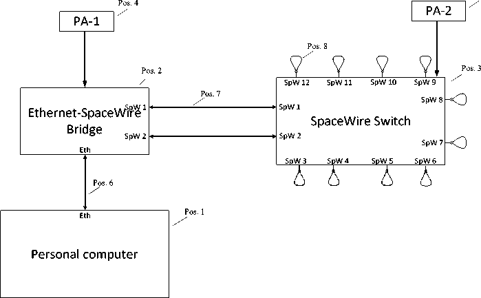
Рис 1. Рабочее место тестирования коммутатора Space Wire
-
Fig. 1. Space Wire switch testing workplace
The Ethernet-Space Wire bridge used when creating tests is the development of the team of LLC SPC "MT" [9] – a domestic company engaged in the production and development of equipment and software for designing and testing aviation and space computing systems based on the Space Wire and Space Fibre standards.
The Space Wire switch used in the tests is a radiation-tolerant fault-tolerant ultra-large-scale integrated circuit (ULSIC) [10] of a Layer 3 programmable master switch [11].
Testing algorithms
To test the switch, special software (SW) was developed. To interact with the operator with this open source software, a console user application is used, the operation with which is described in detail in the testing methodology [12]. Working with the application can be divided into 3 main parts:
-
- preparation for testing (without interaction with the switch);
-
- basic testing of the switch;
-
- extended testing of the switch.
The preparation for testing part describes how to configure the interface bridge as well as how to set the required test parameters.
The basic switch testing part describes the 3 main tests for this technique: the basic test, the load test, and the exception test.
The basic test is designed to check the correctness of processing incoming packets in accordance with the principle of header removal for all ports of the switch (path addressing).
Small data packets are sent from the first port of the test device with a path address containing the corresponding switch port number and the port number to send back to the bridge. After sending packets to each port, the bridge waits for them to return. If all packets have been received, a message is displayed indicating that the test is passed successfully. If the packets do not come back to the testing device, then after a few seconds a message will be displayed about the completion of the test with an error.
The block diagram of the basic test of the switch is shown in Fig. 2.
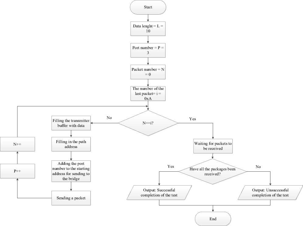
Рис. 2. Блок-схема базового теста коммутатора
-
Fig. 2. Block diagram of the basic test of the switch
The main task of the load test is to check the response of the switch to received data packets which do not contain port numbers in their way address for sending to another device, i.e. not leaving the switch.
On the testing device, two types of packets are formed and sent. Packets of the first type must be sent from the first port of the testing device, successfully pass through the switch path addresses and then return to the bridge, after that they are displayed in the receive buffer. Packets of the second type, which are sent from the second port of the testing device, do not contain the switch port number in their path address to return to the bridge, therefore, they circulate inside the switch until the path addressing is completed, what leads to the switching matrix loading [13]. The path addresses of packets of each type are increased with every second packet, until the limit value of the number of packets set in the configuration file before testing is reached.
The path addresses of packets coming from each port of the testing device do not cross with each other.
The test is considered passed, if the bridge receives all packets of the first type. Otherwise, an error message is displayed about the completion of the test.
The block diagram of the switch load test is shown in Fig. 3.
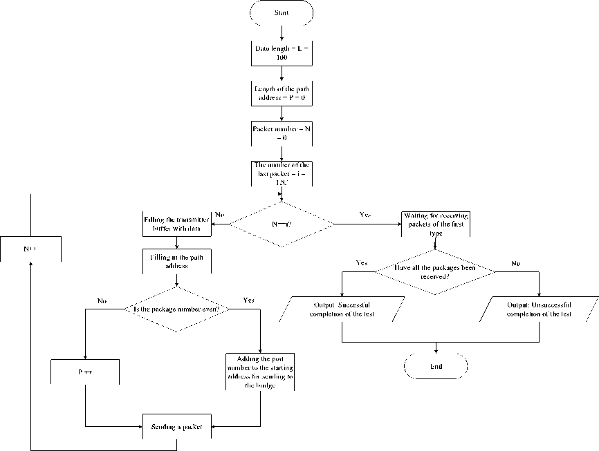
Рис. 3. Блок-схема нагрузочного теста коммутатора
-
Fig. 3. Block diagram of the switch load test
The main task of the exceptional situation test is to check the functionality of the switch when its receiving buffer is loaded as a result of sending a packet to it which creates a queue.
On the testing device, a data packet is formed and sent, containing in its path address the port number (physically closed to the loopback cable), repeated 2 or more times in a row. Such packets are sent for each switch port. The test checks the handling of the situation when the port is busy transmitting a packet, and more data is coming to it, thereby creating a queue. Until the port becomes free, incoming new data is placed in the switch receive buffer. An exceptional situation is reached when the receive buffer overflows [14].
The switch must successfully transmit data packets if its size does not exceed the allocated size of the receiving buffer of the port. The length of the data packet is set in the file before the beginning of testing. The test is considered passed if the bridge receives data packets at their maximum length specified in the configuration file before testing. Otherwise, an error message is displayed about the completion of the test.
The block diagram of the exceptional situation test is shown in Fig. 4.
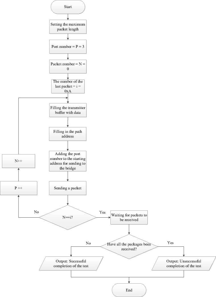
Рис. 4. Блок-схема теста исключительной ситуации
-
Fig. 4. Block diagram of the exceptional situation test
To conduct extended testing, a preliminary configuration of the switch is required, which consists in writing certain values to the rows of the routing table.
The memory areas of different switches are organized differently, and therefore, this part of the open source software can be edited. The extended switch testing part describes the 3 main tests for this methodology: the routing table test, the broadcast test, and the AGR test.
For the switch, the routing table rows corresponding to Table 2 are written.
Table 2
Routing Table Rows
|
Logical address (hex) |
Physical port of the switch |
Note |
|
20 |
1 |
- |
|
21 |
2 |
- |
|
22 |
3 |
- |
|
23 |
4 |
- |
|
24 |
5 |
- |
|
25 |
6 |
- |
|
26 |
7 |
- |
|
27 |
8 |
- |
|
28 |
9 |
- |
|
29 |
10 |
- |
|
2A |
11 |
- |
|
2B |
12 |
- |
|
2C |
1, 2 |
Broadcast |
|
2D |
3-12 |
Broadcast |
|
2E |
1, 2 |
AGR |
|
2F |
3-7 |
AGR |
|
30 |
8-12 |
AGR |
The routing table test is a complete analogue of the basic switch test. It also verifies if incoming packets are processed correctly according to the header stripping principle for all switch ports, but the packet headers are set according to the lines recorded in the routing table.
The block diagram of the switch routing table test is shown in Fig. 5.
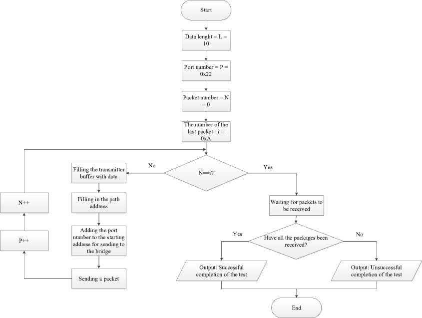
Рис. 5. Блок-схема теста таблицы маршрутизации
-
Fig. 5. Block diagram of the routing table test
The main objective of the broadcast test is to check the switch's ability to send a single packet of data from multiple ports simultaneously (broadcast).
On the testing device, a data packet is formed with two addresses in the header: 2d and 2c. This packet, after being sent, must reach the switch, then by the first address 2d move to 10 different ports of the switch (from the 3rd to the 12th). Due to the fact that these ports are closed to loopback cables, 10 packets will then arrive at the switch, with the address 2c in the header. Each of them is sent broadcast to the 1st and 2nd ports of the switch, which are connected to the test device. As a result, 20 data packets are already sent to the interface bridge. If all packets are received, then a message is displayed that the test has been completed successfully; otherwise, a message is displayed that the test is completed with an error.
The flowchart of the broadcast test is shown in Fig. 6.
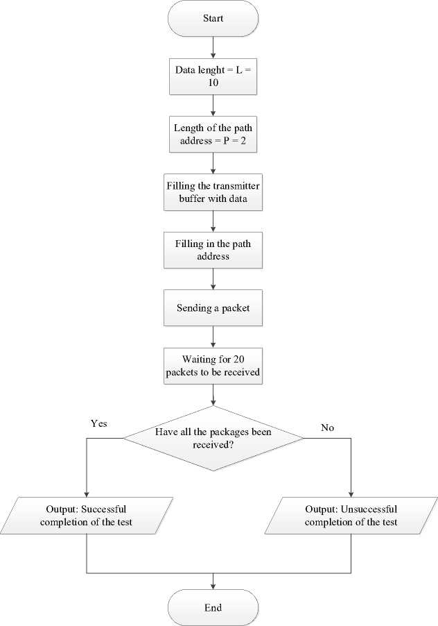
Рис. 6. Блок-схема теста широковещания
-
Fig. 6. Block diagram of the broadcast test
The main objective of the AGR test is to check the ability of the switch, when selecting multiple ports for data transmission (broadcast), to send these packets from the port with the highest priority.
The test includes additional switch configuration in the form of setting priority levels for ports. The switch used for testing supports 8 priority levels, and therefore it is not possible to set one’s own priority level for each port (12). Ports have the following priority levels:
-
- for ports 1 and 2 - 1 and 2, respectively;
-
- for ports 3–7 – from 1 to 5, respectively;
-
- for ports 8–12 – from 1 to 5, respectively.
The test data packet is sent from the interface bridge with three addresses: 2f, 30 and 2e. The data packet must reach the switch, then by the first address move to 5 different ports of the switch (from the 3rd to the 7th). However, since the AGR is set, the port with the highest priority is selected, i.e. the 7th. Due to the fact that this port is closed to the loopback cable, the switch will then receive 1 packet, with the address 30, 2e in the header. Similarly, the packet is sent to ports 7-12. With AGR, only the port with the highest priority is selected. After that, the packet is sent to address 2e on the 1st and 2nd ports, of which the 2nd one will be selected due to the higher priority. As a result, a single data packet should arrive at the interface bridge. In this case, a message about the successful completion of the test is displayed. If no packet is received, or more than one packet is received, a message is displayed that the test is completed with an error.
The block diagram of the AGR test is shown in Fig. 7.
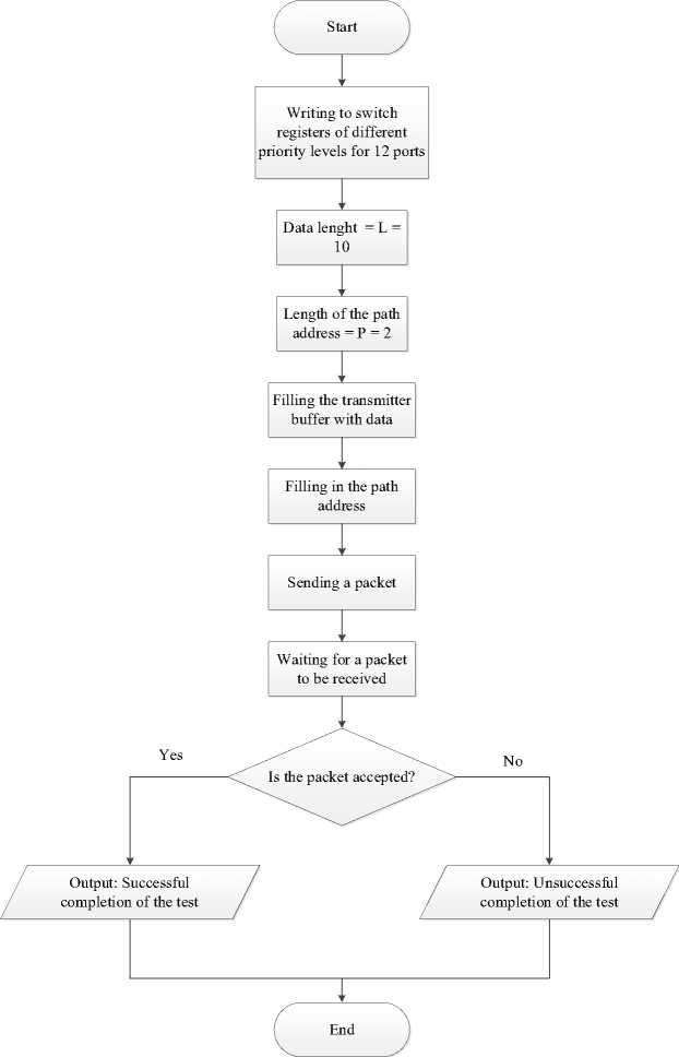
Рис. 7. Блок-схема теста адаптивной групповой маршрутизации
Fig. 7. Block diagram of adaptive group routing test
Conclusion. In the course of working with the switch, the correctness of each of the tests of the developed methodology was confirmed, so that it is possible to say that the methodology is able to verify some of the points of the Space Wire standard, such as header deletion, broadcast data transmission, AGM. The technique also allows to check the provisions of the documentation of the switches, such as the possibility of specifying a routing table, the set size of the receiving buffer of each of the ports, erasing packets with a missing sending address to the port.
In the future, the testing methodology will be supplemented with new checks, among which it is now possible to highlight the verification of the possibility of mirroring incoming and outgoing traffic from the device [15].
References Development of a methodology for testing SpaceWire network switches
- Kommutatory kak osnova seti peredachi dannyh [Switches as the basis of a data transmission network] (In Russ.). Available at: https://www.sekventa.ru/service/sks/aktivnoe-setevoe-oborudovanie.html (accessed: 25.12.2021).
- Gorbunov S. F., Grishin V. Yu., Eremeev P. M. [Network interfaces of spacecraft: prospects of development and problems of implementation]. Nanoindustriya. 2019, No. 89, P. 128–130 (In Russ.).
- ECSS-E-ST-50-12C Rev.1. Space engineering. SpaceWire – Links, nodes, routers and networks. ECSS Secretariat. ESA-ESTEC Requirements & Standards. Division Noordwijk, The Netherlands.
- Marshrutizaciya – princip raboty i tablica marshrutizacii [Routing - the principle of operation and the routing table] (In Russ.). Available at: https://zvondozvon.ru/tehnologii/kompyuternye-seti/marshrutizatsiya (accessed: 03.01.2022).
- Vidy trafika v IP setyah: unicast, broadcast, multicast, anycast. Loopback adresa i interfejsy [Types of traffic in IP networks: unicast, broadcast, multicast, unicast. Loopback addresses and inter-faces] (In Russ). Available at: https://zametkinapolyah.ru/kompyuternye-seti/4-8-vidy-trafika-v-ip-setyax-unicast-broadcast-multicast-anycast-loopback-adresa-i-interfejsy.html#484__broadcast (ac-cessed: 03.01.2022).
- Kalimoldaev M. N., Tulemisova G. E. [Algorithm of adaptive routing of information flow of in-tegrated service networks]. Institut problem informatiki i upravleniya MON RK. Kazakhstan, 2013. No. 2. (In Russ.).
- Mosty, interfejsy i vneshnie nakopiteli dannyh [Bridges, interfaces and external data storage] (In Russ.). Available at: https://www.ixbt.com/storage/bridges.shtml (accessed: 04.01.2022).
- Vvedenie petlevogo kabelja [Introduction of loop cable] (In Russ.). Available at: http://ru. fibre-splitter.com/news/introduction-of-loopback-cable-24290794.html (accessed: 04.01.2022).
- MiT. Oficial’nyj sajt [MiT. Official website] (In Russ.). Available at: http://www. space-wire.ru/mit (accessed: 05.01.2022).
- Cheprasova A. S., Mamelin Yu. V. [The future and present of FPGA]. Molodoy uchenyy. 2016, No. 17, P. 79–81 (In Russ.).
- Bortovye seti kosmicheskih apparatov novogo pokoleniya [Onboard networks of new genera-tion spacecraft] (In Russ). Available at: https://docplayer.com/137755601-Bortovye-seti-kosmicheskih-apparatov-novogo-pokoleniya-na-osnove-setey-tehnologii-spacewire.html (accessed: 06.01.2022).
- Sozdanie konsol’nogo prilozheniya [Creating a console application] (In Russ.). Available at: https://ci-builder.ru/07/Index05.htm (accessed: 07.01.2022).
- Bufery, potoki i dvoichnye dannye [Buffers, streams, and binary data] (In Russ.). Available at: https://ci-builder.ru/07/Index05.htm (accessed: 17.01.2022).
- Ob”yasnenie zerkalirovaniya portov [Explanation of port mirroring] (In Russ.). Available at: https://ci-builder.ru/07/Index05.htm (accessed: 24.01.2022).
- Arhitektura i realizaciya kommutacionnyh matric sovremennymi proizvoditelyami elementnoj bazy [Architecture and implementation of switching matrices by modern manufacturers of the element base] (In Russ). Available at: https://ci-builder.ru/07/Index05.htm (accessed: 25.01.2022).
