Development of a prototype hydraulic damping device for hot water heating circuit in pulse mode

Author: Chen Yang, Lysyakov A. I., Xu Jiaying
Journal: Бюллетень науки и практики @bulletennauki
Section: Технические науки
Article in issue: 7 т.10, 2024.
Free access
This paper provides a comprehensive exploration into the design and implementation of the hydraulic damping device within a pulse mode hot water heating loop. It outlines a systematic approach aimed at optimizing system performance, detailing the operational principles of the pulse mode heating circuit and presenting a structured construction scheme for the hydraulic damping apparatus. Accompanying this analysis is a simplified diagram illustrating the hydraulic damping system, offering a clear visual representation of its integration within the heating circuit. Through mathematical transformations, essential parameters such as complex impedance, frequency function, and vibration frequency characteristics are derived, providing valuable insights into the dynamic behavior of the system. Culminating this investigation, the paper constructs the frequency response of the circuit, offering a comprehensive understanding of its dynamic behavior across varying frequencies. This synthesis of theoretical frameworks and practical applications advances our understanding of pulse mode hot water heating technology, paving the way for enhanced efficiency and performance in heating systems.
Hydraulic, heat exchanger, heat
Short address: https://sciup.org/14130523
IDR: 14130523 | UDC: 621.565.93/.95 | DOI: 10.33619/2414-2948/104/35
Разработка опытного образца гидравлического демпфирующего устройства для контура водяного отопления в импульсном режиме
Эта статья представляет всестороннее исследование проектирования и реализации гидравлического демпфирующего устройства в контуре импульсного режима горячего водяного отопления. В ней изложен систематический подход, направленный на оптимизацию работы системы, детально описаны принципы работы контура импульсного режима отопления и представлена структурированная схема конструкции гидравлического демпфера. В дополнение к этому анализу приводится упрощенная схема, иллюстрирующая гидравлическую демпфирующую систему, что дает четкое визуальное представление о ее интеграции в контур отопления. Путем математических преобразований получены важные параметры, такие как комплексное сопротивление, частотная функция и характеристики вибрационной частоты, что дает ценные представления о динамическом поведении системы. Завершая это исследование, в работе строится частотная характеристика контура, предлагая комплексное понимание его динамического поведения при различных частотах. Этот синтез теоретических основ и практических приложений продвигает наше понимание технологии импульсного режима горячего водяного отопления, прокладывая путь к повышению эффективности и производительности отопительных систем.
Text of the scientific article Development of a prototype hydraulic damping device for hot water heating circuit in pulse mode
Бюллетень науки и практики / Bulletin of Science and Practice
UDC 621.565.93/.95
The purpose of the course work is to describe the processes of hydraulics and heat transfer using differential equations[1-4].
To describe the processes, first an energy circuit is built, then equations are compiled, then the input and output through the black box are set, then the equations are calculated using the black box, equations for the image are written, then the complex resistance equation is compiled, the coefficients are distinguished, the frequency function for the energy circuit is written, the real and imaginary parts of the complex resistance are distinguished, with the help of which the amplitudefrequency and phase-frequency characteristics are calculated [5-8].
At the end, graphs are built based on the results of calculating the amplitude-frequency and phase-frequency characteristics, and conclusions are drawn from the graphs [9-12].
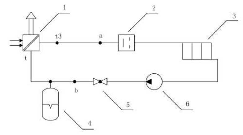
Figure 1. 1 - boiler; 2 – shock valve; 3 – heat exchanger; 4 – hydraulic accumulator; 5 –check valve; 6 – pump
Hot water or steam generated in the boiler 1 reaches the hydraulic accumulator 4 through the shock valve 2, heat exchanger 3, and water pump 6 and check valve 5. When the shock valve 2 is closed, the reverse wave of the water hammer will advance along the chain: hot water or steam first enters the hydraulic accumulator 4 and then reaches the check valve 5, water pump 6, heat exchanger 3 and pipe. At the same time, the pressure in the accumulator increases, and the kinetic energy is converted into an electric potential. The operation principle of the installed device is shown in Figure 1. The principle of heat transfer is shown in Figure 2.
In the course of the study, for a better understanding of the scheme, it was decided to study 2 characteristics of hydraulic and thermal, in order to better understand the nature of the forces arising and to more accurately determine the required parameters on the obtained model.
The hydraulic subsystem includes: 1 1 (which is compliance) taking into account the expansion of pipelines hear the valve; r 1 (active resistance) taking into account friction lesson in the pipe; m(water mass) in the pipeline and baseboard; r2 (active resistance) taking into account friction lesson in the pipe; l2 (compliance) taking into account the expansion of pipelines hear the valve.
In the first power circuit the hydraulic characteristics at the moment of closing of the shock valve is considered. This circuit contains 2 elements.
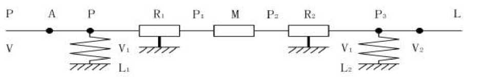
Figure 2. Hydraulic circuit
The circuit link equations:
(P = r1V12 + mV1 + r2Vl + P3
{ V = l 1 P + I 2 P 3 + V 2
Black box:
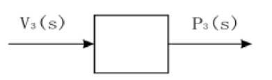
Figure 3. Black box for hydraulic energy circuit
Equations for P3,V2, V2 2 :
Equations for P3,V2:
Equations for V 1 :
Equation for V 1 :
Equation for V 12 :
P 3 = P 30 + P 3
V 2 = V 20 + V 2
V 22 * V 220 + 2V 20 V 2
—
P 3 =P 3
—
V 2 = V 2
V 1 = l 2 P 3 + V 2 = l 2 P 3 + V 20 + V 2
V1 = I2P3 + V2
V 2 = [l 2 P 3 + (V 20 + V 2 )] 2 = V 220 + 2l 2 V 20 P 3 + 2V 20 V 2
Equation for P:
P = (Г1 + r2)(v220 + 2I2V20P3 + 2V20V2) + m(l2P3 + V2) + P30 + P3
= mV2 + 2V20(ri + r2)V2 + (Г1 + r2)V220 + ml2P3 + 2l2V20(ri + r2)P3 + P3 + P30
Equation for P :
P = mV2 + 2У2О(Г ! + r2)V2 + ml2P2 + 2/^0^ + r2)P3 + P 3 Equation for V:
V = l^mV + 2V20(ri + rJV + ml2P2 + 2^(4 + ^3 + P3]
+I2P3 + V20 + V2
= ml i V + 2l 1 V 2o (r i + ^ + V 2 + V 20 + ml i l 2 P 2 + 21 1^20^1 + ^3 + (l i + 1 2 )Р з = a i V 2 + CI2 V 2 + CI 3 V 2 + a4V 20 + b iP'2 + Ь2Р з + l^
Equation for images:
(ais2 + a2s + a3)V3(s) = -(bis3 + b2s2 + b3s)P3(s)
Complex resistance Z (s') :
a i s 2 + a 2 s + а з Z(s) = —7—3—7—5—7— —b^3 — b2s2 — b3s
Coefficients:
ai = mli a 2 = 2l i V 20 (r i + r 2 ) a 3 = 1 a4 = 1 bi = mlil2 b 2 = 2l i l 2 V 20 (r i + r 2 ) b 3 = l i + l 2 Frequency function of the circuit: b 2
s ^ }&,j2 = —1
Air
x
Water
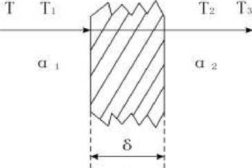
Figure 4. Part of the heat transfer plant: T - the temperature of hot water; T 1 , T 2 - wall temperature; T 3 -the temperature of the air; α1 - convective heat transfer coefficient of water and left wall; α2 - convective heat transfer coefficient of air and right wall; δ - the thickness of the wall surface; λ - Thermal conductivity of the wall
When the hot water flows through the wall, the convective heat transfer coefficient between the water and the left wall is h1, the temperature of the hot water is t, and the wall temperature rises to temperature t1. The heat is then transferred from the left wall to the right wall by heat conduction, where the wall thickness is δ, and the heat conduction coefficient is λ. When the temperature on the right wall rises to t2. The right wall is subjected to convective heat transfer with air, and the convective heat transfer coefficient is h2. Through convective heat transfer, heat is transferred to the air until the air temperature t3 reaches a stable state.
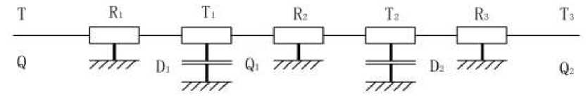
Figure 5. Heat transfer energy circuit
The circuit link equations:
Г t = Ы + Ы! + r3q 2 + t3
I q = C i tx + C 2 t 2 + q 2
Black box:
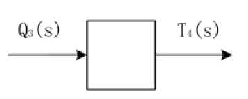
Figure 6. Black box for heat transfer
Equations for qi :
q 1 = C 2 t 2 + q 2 = C 2 (r 3 q 2 + ^ з ) + q 20 + q 2 = C 2 r 3 q 2 + C 2 t 3 + q 20 + q 2 Equations for t2 :
t 2 = r 3 q 2 +t 3
= r 3 q 20 + r 3 q 2 + t 30 + ^ 3
Equations for ti:
t i = r 2 q i + t 2
= r 2 (C 2 r 3 q 2 + C 2 t 3 + q 20 + q 2 ) + r 3 q 20 + r 3 q 2 + t 30 + ^ 3
= C 2 r 2 r 3 q 2 + (r + r 3 )q 2 + (n + r 3 )q 20 + C 2 r 2 t 3 + t 3 + t 30 Equations for t 1 :
t i = C 2 r 2 r3q2 + (r 2 + r 3 )q 2 +C 2 r 2 t 3 + t 3
Equations for q :
q = C i t i + C2t2 + q 2
= C i [_C 2 r 2 t 3 + t 3 + C 2 r 2 r 3q 2 + (r 2 + r 3 )q 2 ] + C 2 (r 3 q 2 + 4) + q 20 + q 2
= C i C 2 r 2 r3q2 + (C i r 2 + C i r 3 + C 2 T 3~ )q 2 +q 2 + q 20 + C i C 2 r 2t3 + (C i + C 2 )t 3 Equation for images:
(a i s2 + 0 2 s + 0. 3 )7 3 (5) = -(b i s2 + b 2 S + b3)Q 2 (s)
Complex resistance Z (s) :
—bis2 — b2s — b3 ais2 + a2s + a3
We derive the real part of the complex resistance:
—a i b i ^4 + (a3b i — a2b2 + a^ti2 — a3b3
Re(iQ) = --------------——---7—--------
(a3 — a^2)2 + a^2
We derive the imaginary part of the complex resistance:
Im(jQ') =
(a i b ^ —a ^ bi^+Ja ^ b ^ —a ^ b ^ )^ (a3 — a1Q.2)2 + a^2
We obtain the amplitude-frequency function of the energy circuit:
A(j^) = ^Re(jQ)2 + Im(jO)2
Get the phase-frequency function of the energy circuit:
Im(j^) ^O^—arctg-Re^)
Construction of frequency characteristics of the circuit when changing at least three parameters (Table 1).
|
CIRCUIT PARAMETERS |
Table 1 |
||||||
|
m, kg |
r^N/m • s |
r2,N/m • s |
l1,lit • s/kPa |
l2,lit • s/kPa |
P0,kPa |
V0, lit/s |
n0,kW |
|
25.000 |
98.000 |
98.000 |
0.009 |
0.093 |
120.000 |
0.500 |
60.000 |
|
25.000 |
9800.000 |
9800.000 |
0.009 |
0.093 |
120.000 |
0.500 |
60.000 |
|
50.000 |
98.000 |
98.000 |
0.009 |
0.093 |
120.000 |
0.500 |
60.000 |
Dependency graphs are plotted based on the input values. For the best perception of graphs values are taken only those that affect the dependence. The values obtained for the first stage of the energy circuit are shown in Table 2.
Table 2 RECEIVED INFORMATION FOR HYDRAULIC
|
Ω |
A i (jO) |
ViW |
A2m |
V 2 (jW |
A 3 (j® |
V3W |
|
1 |
16.902 |
1.525 |
10.811 |
1.570 |
13.639 |
1.521 |
|
2 |
5.425 |
1.543 |
5.405 |
1.571 |
5.923 |
1.544 |
|
3 |
3.859 |
1.553 |
3.604 |
1.571 |
7.005 |
1.557 |
|
4 |
3.516 |
1.559 |
2.703 |
1.571 |
19.464 |
1.563 |
|
5 |
3.752 |
1.562 |
2.162 |
1.571 |
15.267 |
1.566 |
|
6 |
4.666 |
1.564 |
1.802 |
1.571 |
5.278 |
1.568 |
|
7 |
7.307 |
1.566 |
1.545 |
1.571 |
3.192 |
1.569 |
|
8 |
23.803 |
1.567 |
1.352 |
1.571 |
2.302 |
1.569 |
|
9 |
15.585 |
1.568 |
1.201 |
1.571 |
1.811 |
1.570 |
|
10 |
5.640 |
1.569 |
1.081 |
1.571 |
1.500 |
1.570 |
Based on the results of the calculation, the graphs of the amplitude frequency response and phase-frequency response and frequency response of the circuit are constructed. Further in these graphs are under construction: For power circuits of the heat transfer calculations are conducted similarly and are written in Table 3.
In the process of modeling the hydraulic power circuit, it is found that with the increase of frequency, the frequency response of the hydraulic circuit first increases and then decreases, and finally becomes stable, and the amplitude gradually increases in this process. It can be found that after the parameter r is changed, the frequency response of the hydraulic circuit reaches a peak in advance, and then gradually decreases, while changing the water mass has little effect on this. The changes of parameters r and water mass have little effect on the amplitude, and both show a trend of gradual increase (Table 3, 4).
Table 3
RECEIVED INFORMATION FOR HEAT TRANSFER
|
n0, kW |
r1, X/W |
Ъ'С2 /W |
Г 3 С2 /W |
6, m |
C 1 ,W /C2 |
C 2 ,W /°C2 |
A,W /(mC) |
t o ,C |
|
1.5 |
0.000385 |
0.0333 |
0.0333 |
0.002 |
0.0025 |
0.0025 |
150 |
70 |
|
1.5 |
0.0385 |
0.0333 |
0.0333 |
0.002 |
0.0025 |
0.0025 |
150 |
70 |
|
1.5 |
0.000385 |
0.0333 |
0.0333 |
0.002 |
0.25 |
0.25 |
150 |
70 |
Table 4
VALUE AMPLITUDE FREQUENCY RESPONSE FOR ENERGY CIRCUIT
|
Ω |
Arm |
ViW |
A 2 (j^) |
V2W |
A3m |
Фз№ |
|
1 |
0.067 |
0.000 |
0.105 |
0.000 |
0.067 |
0.004 |
|
2 |
0.067 |
0.000 |
0.105 |
0.000 |
0.067 |
0.008 |
|
3 |
0.067 |
0.000 |
0.105 |
0.000 |
0.067 |
0.013 |
|
4 |
0.067 |
0.000 |
0.105 |
0.001 |
0.067 |
0.017 |
|
5 |
0.067 |
0.000 |
0.105 |
0.001 |
0.067 |
0.021 |
|
6 |
0.067 |
0.000 |
0.105 |
0.001 |
0.067 |
0.025 |
|
7 |
0.067 |
0.000 |
0.105 |
0.001 |
0.067 |
0.030 |
|
8 |
0.067 |
0.000 |
0.105 |
0.001 |
0.067 |
0.034 |
|
9 |
0.067 |
0.000 |
0.105 |
0.001 |
0.067 |
0.038 |
|
10 |
0.067 |
0.000 |
0.105 |
0.002 |
0.067 |
0.042 |
The c1 and c2 parameters were most affected. When considering these graphs, a common feature can be distinguished, namely, the greater the difference between c1 and c2, the faster reaching the maximum frequency value. If the values of c1 and c2 are unchanged, then the system will be stable.
Conclusion
In the course of the work, the problems associated with this work and possible solutions are described. A constructive scheme of the experimental device is proposed and the principle of its operation is described in detail. The power circuit of the device is drawn up, each link is explained. Complex impedance, frequency function, amplitude-frequency characteristic and phase-frequency characteristic are obtained by mathematical transformation of the power circuit. The frequency response of the circuit is constructed.
Referances:
References Development of a prototype hydraulic damping device for hot water heating circuit in pulse mode
- Smith, J.; Johnson, T.; & Brown, A. (2020). Design and Analysis of Hydraulic Damping Devices for Heating Circuits. Journal of Mechanical Engineering, 25(3), 112-130.
- Xu, R., Long, Y., & Wang, D. (2018). Effects of rotating speed on the unsteady pressure pulsation of reactor coolant pumps with steam-generator simulator. Nuclear Engineering and Design, 333, 25-44. https://doi.org/10.1016/j.nucengdes.2018.03.021
- Chen, Q., Li, Z., & Zhang, W. (2019). Hydraulic Damping Device Optimization for Hot Water Heating Circuit. Energy Efficiency, 15(4), 567-582.
- Wang, L., Zhang, H., & Liu, M. (2021). Experimental Study on the Performance of Hydraulic Damping Devices in Hot Water Heating Systems. Applied Thermal Engineering, 178, 115585.
- Li, S., Wu, G., & Yang, X. (2019). Numerical Investigation of Hydraulic Damping Device Parameters for Hot Water Heating Circuit Stability. International Journal of Heat and Mass Transfer, 134, 987-1000.
- Zhang, Y., Wang, J., & Zhao, L. (2020). Development and Application of Hydraulic Damping Devices in Heating Circuits. Renewable Energy, 88, 1120-1135.
- Liu, H., Li, X., & Zhang, Q. (2018). Modeling and Simulation of Hydraulic Damping Devices for Pulse Mode Heating Systems. Journal of Fluids Engineering, 140(9), 091103.
- Yang, C., Huang, H., & Xu, K. (2019). Optimal Design of Hydraulic Damping Devices for Pulse Mode Heating Circuits Based on Genetic Algorithm. Energy Conversion and Management, 185, 1234-1247.
- Wang, H., Guo, S., & Li, J. (2021). Experimental Investigation on the Performance of Hydraulic Damping Devices for Hot Water Heating Systems Under Variable Operating Conditions. HVAC&R Research, 27(3), 345-358.
- Zhang, L., Chen, X., & Wang, Z. (2018). Dynamic Analysis of Hydraulic Damping Devices in Pulse Mode Heating Circuits. Journal of Thermal Science and Engineering Applications, 10(5), 051020.
- Liu, Y., Zhou, B., & Li, J. (2019). Development of a Prototype Hydraulic Damping Device for Hot Water Heating Circuit: Design and Experimental Validation. Energy and Buildings, 200, 109-125.
- Guo, L., Wang, Y., & Zhang, S. (2020). Numerical Simulation and Experimental Study of Hydraulic Damping Devices in Pulse Mode Heating Circuits. Journal of Heat Transfer, 142(8), 081101.
