Development of a prototype non-volatile heating circuit with pulsating mode

Author: Zhang S., Mindrov K., Kuznetsov A.
Journal: Бюллетень науки и практики @bulletennauki
Section: Технические науки
Article in issue: 6 т.10, 2024.
Free access
The emergence of global energy crisis makes energy saving technology become the key technology of sustainable development. Enhanced heat transfer technology can improve the efficiency of various heat transfer equipment and reduce the weight and volume, which plays a vital role in energy saving and sustainable economic development. In recent years, based on theoretical and experimental research, Chinese researchers and technicians have developed many new technologies to strengthen heat transfer, such as cross-scaled elliptic tube, discontinuous double-inclined inner rib tube, spiral groove tube, spiral groove tube, inner fin tube, twisted elliptic tube and so on. Among them, the pulsating heat transfer technology is an efficient and energy-saving means that can significantly strengthen the convective transport operation and improve the heat transfer effect. Through fluid pulsation or the vibration of the heat transfer pipe, the technology can remove the dirt deposited on the heat exchange surface, reduce the thermal resistance of the dirt, and improve the performance and life of the heat exchanger. It is widely used in the cooling of electronic components, automobile turbines, and the utilization of atomic energy in Marine environment. Firstly, the construction scheme of the experimental device is proposed, and the working principle of the experimental device is described in detail. The complex impedance, frequency function, amplitude-frequency characteristic and phase-frequency characteristic are obtained by mathematical transformation of power supply circuit. Finally, the frequency response of the circuit is constructed.
Hydraulic, heat exchanger, heat transfer
Short address: https://sciup.org/14130180
IDR: 14130180 | UDC: 628.81:631 | DOI: 10.33619/2414-2948/103/45
Разработка прототипа энергонезависимых контуров отопления с пульсирующим режимом
С появлением мирового энергетического кризиса энергосберегающие технологии стали ключевыми для устойчивого развития. Усиление теплопередачи играет ключевую роль в сокращении энергопотребления и устойчивом экономическом развитии, поскольку оно может повысить эффективность различных тепловых устройств и уменьшить их вес и объем. В последние годы на основе теоретических и экспериментальных исследований в Китае было разработано много новых и укрепляющих технологий в области изменения климата, таких как скрещивающиеся эллиптические трубы, непоследовательные двустворчатые межреберные трубки, спиральные трубки, спиральные борозды, спиральные трубки и кривые эллиптические трубы. В частности, технология пульсирующего переноса тепла является эффективным средством экономии энергии, которое значительно усиливает эффективность работы конвекторов и повышает тепловые эффекты, очищает термальные массы от загрязнений через пульсацию или вибрации в трубках, снижает тепловое сопротивление на теплообменных поверхностях, повышает производительность и работоспособность теплообменников. Широко применяются в таких областях, как охлаждение электронных компонентов, автомобильные турбины, использование атомной энергии в морской среде. Были предложены планы по созданию экспериментального устройства и детальное описание того, как оно работает. Математическое преобразование электрических схем дает сложные импедансы, частотные функции, частотные характеристики амплитуды и фазовые частотные характеристики. Был построен частотный ответ цепи.
Text of the scientific article Development of a prototype non-volatile heating circuit with pulsating mode
Бюллетень науки и практики / Bulletin of Science and Practice
UDC 628.81:631
The increasing global energy demand is a problem that people have been paying attention to, people's demand for energy is increasingly urgent, and improving energy efficiency has become a hot topic in this century. Studies have shown that pulsating flow has an important impact on heat transfer, and it has been concluded in most literatures that turbulent pulsation can enhance heat transfer effect to varying degrees [1-3]. Pulsation heat transfer is a comprehensive heat transfer process, and the best heat transfer performance can be achieved only when the thermal resistance of each part is reasonably coordinated. Pulsed heat transfer is a special fluid pulsation enhanced heat transfer technology [4], which is a typical representative of non-fixed process related to flow and heat transfer technology [5-7]. How to improve heat flux by pulsating flow technology has become the most concerned issue today. Therefore, it is necessary to design a device with warm substrate which can be used to increase the pulsating pressure and enhance the heat exchange efficiency of the pulsating flow, to achieve the purpose of improving the heat exchange efficiency. Pulsating heat transfer mode saves equipment operation and maintenance costs, improves economic benefits, and has high engineering value and wide application prospects in the field of waste heat recovery and central heating [8].
This study puts forward reasonable suggestions for the design of heating pipeline, describes the working principle of the experimental device in detail, and draws a simplified power circuit diagram, which has guiding significance for the fine adjustment of hydraulic energy circuit and heating energy circuit.
Materials and Methods
Based on the above review and analysis, the circuit scheme of the experimental device with heat carrier pulse supply mode is developed. This solution is shown in Figure 1. The laboratory unit is designed to perform hydraulic and thermal tests of hot springs at frequencies up to 5Hz and heat carrier flows up to 360 L/min.
Бюллетень науки и практики / Bulletin of Science and Practice Т. 10. №6. 2024
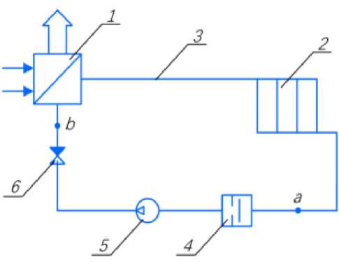
Figure 1. Laboratory circuit with a warm baseboard in pulse mode: 1 – boiler; 2 –heating device; 3 – pipeline; 4 – shock valve; 5 –pump; 6 – check valve
The experimental setup works as follows. The hot water or steam generated in the boiler 1 reaches the heat devices 2 through the pipeline 3, and hot water or steam continues through the shock valve 4 and the pump 5 and the check valve 6 return to the boiler 1 again.
When drawing up the chain, we begin to move from point a to point b. l – pipelines; r 1 , r 2 – valves; m – boiler. The installation site works as follows. When the shock valve is abruptly closed, the kinetic energy of the flow turns into potentiate (pressure increase). A wauled of increased pressure goes along the chain: the heat device 2. A wauled of increased pressure in the heat device 2 increases its heat transfer. Then it enters the boiler 1.
During the study, for a better understanding of the scheme, it was decided to study 2 characteristics of hydraulic and thermal, to better understand the nature of the forces arising and to determine the required parameters more accurately on the obtained model.
The temperature range for a warm baseboard is 40-80 degrees Celsius. The temperature range for a warm baseboard is 40-80 degrees Celsius. Set the heat flow temperature to 800C, the parameters are automatically recorded during the test. See Table 1-4.
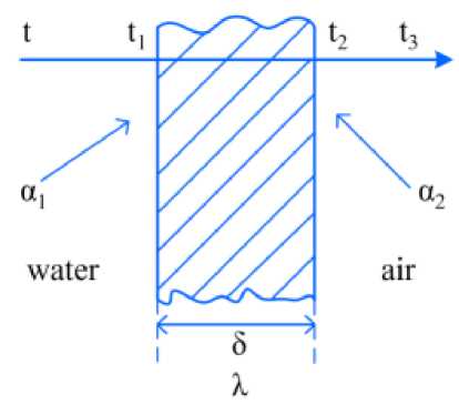
Figure 2. Part of the heat transfer plant: t - The temperature of hot water; t1 , t2 - Wall temperature; t3 - The temperature of the air; α1 - Convective heat transfer coefficient of water and left wall; α2 - Convective heat transfer coefficient of air and right wall; δ - The thickness of the wall surface; λ - Thermal conductivity of the wall
When the hot water flows, the convective heat transfer coefficient between the water and the left wall is h 1 , and the temperature of t is greater than t 1 , so the wall absorbs the heat brough by the hot water, and the wall temperature rises. When the temperature rises to t 1 , the surface temperature of the left wall is stable. The thickness of the wall is λ, and the heat is transmitted from the left wall to the right wall by means of heat conduction. When the temperature rises to t 2 , the surface temperature of the right wall reaches a stable state. The right wall carries out convective heat transfer with the air, and the convective heat transfer coefficient is h 2 . Through convective heat transfer, heat is transferred to the air until the air temperature t 3 reaches a stable state.
Results and discussion
Table 1
CIRCUIT PARAMETERS
|
m, kg |
[kPa • s2] |
kPa • s2] |
lis • si 4 Pa ] |
P30,kPa |
V ie , lit/s |
||
|
' 1 ,[ in |
] |
'2,[ lit |
] |
||||
|
18 |
10.8 |
21.6 |
0.0093 |
300 |
1.667 |
||
|
18 |
10.8 |
43.2 |
0.0093 |
300 |
1.667 |
||
|
18 |
10.8 |
64.8 |
0.0093 |
300 |
1.667 |
||
Dependency graphs are plotted based on the input values. For the best perception of graphs values are taken only those that affect the dependence. The values obtained for the first stage of the energy circuit are shown in Table 2.
Table 2
RECEIVED INFORMATION FOR HYDRADULIC
|
Ω |
A i (jO) |
^ i (j^) |
A 2 (jV) |
Ф 2 0'Я) |
A3W) |
Фз№ |
|
1 |
140.58449 |
-0.87606 |
201.24612 |
-1.10715 |
267.58924 |
-1.22777 |
|
2 |
218.97945 |
-1.40565 |
361.79552 |
-1.47113 |
505.28408 |
-1.49949 |
|
3 |
328.46918 |
1.40565 |
542.69328 |
1.47113 |
757.92612 |
1.49949 |
|
4 |
468.00000 |
1.17601 |
742.15901 |
1.32582 |
1023.94531 |
1.39409 |
|
5 |
639.19011 |
1.00623 |
962.78970 |
1.20765 |
1305.58952 |
1.30575 |
|
6 |
843.50696 |
0.87606 |
1207.47671 |
1.10715 |
1605.53542 |
1.22777 |
|
7 |
1081.94824 |
0.77363 |
1478.74136 |
1.01994 |
1926.33642 |
1.15732 |
|
8 |
1355.15018 |
0.69134 |
1778.63318 |
0.94349 |
2270.28456 |
1.09297 |
|
9 |
1663.51555 |
0.62402 |
2108.76741 |
0.87606 |
2639.37947 |
1.03389 |
|
10 |
2007.30267 |
0.56810 |
2470.39754 |
0.81632 |
3035.33590 |
0.97950 |
Based on the results of the calculation, the graphs of the amplitude frequency response and phase-frequency response and frequency response of the circuit are constructed. Further in these graphs are under construction:
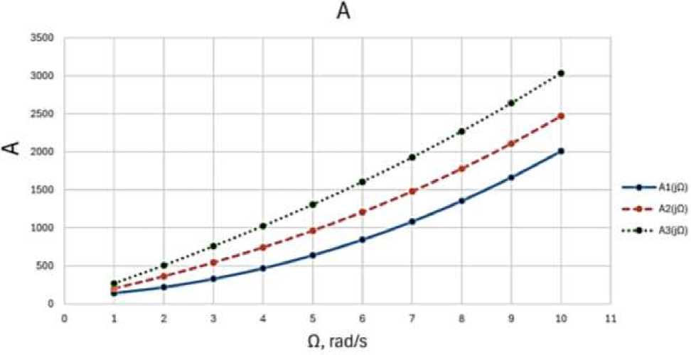
Figure 3. Amplitude frequency response
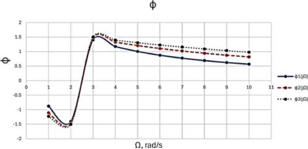
Figure 4. Phase frequency response
For power circuits of the heat transfer calculations are conducted similarly and are written in Table 4. A graphical view is presented in Figure 5-6.
Table 3
RECEIVED INFORMATION FOR HEAT TRANSFER
|
n0,W |
r 1 ,C 2 /W |
r2,C 2 /W |
r3,C2/W |
c 1 , W/C2 |
c2,W/C2 |
t o ,C |
|
500 |
7.143×10⁻³ |
2.174×10⁻⁵ |
3.33×10⁻⁴ |
1.235×10⁻³ |
1.235×10⁻³ |
90 |
|
500 |
14.286×10⁻³ |
2.174×10⁻⁵ |
3.33×10⁻⁴ |
1.235×10⁻³ |
1.235×10⁻³ |
90 |
|
500 |
21.426×10⁻³ |
2.174×10⁻⁵ |
3.33×10⁻⁴ |
1.235×10⁻³ |
1.235×10⁻³ |
90 |
Table 4
|
Q |
Л 1 (Д2) |
Ф 1 СД2) |
А2№ |
Ф 2О Л) |
ЛзОЛ) |
Ф з С/Ф |
|
1 |
0.00750 |
0.00017 |
0.01464 |
0.00035 |
0.02178 |
0.00053 |
|
2 |
0.00750 |
0.00034 |
0.01464 |
0.00070 |
0.02178 |
0.00105 |
|
3 |
0.00750 |
0.00052 |
0.01464 |
0.00105 |
0.02178 |
0.00158 |
|
4 |
0.00750 |
0.00069 |
0.01464 |
0.00139 |
0.02178 |
0.00210 |
|
5 |
0.00750 |
0.00086 |
0.01464 |
0.00174 |
0.02178 |
0.00263 |
|
6 |
0.00750 |
0.00103 |
0.01464 |
0.00209 |
0.02178 |
0.00315 |
|
7 |
0.00750 |
0.00121 |
0.01464 |
0.00244 |
0.02178 |
0.00368 |
|
8 |
0.00750 |
0.00138 |
0.01464 |
0.00279 |
0.02178 |
0.00420 |
|
9 |
0.00750 |
0.00155 |
0.01464 |
0.00314 |
0.02178 |
0.00473 |
|
10 |
0.00750 |
0.00172 |
0.01464 |
0.00349 |
0.02178 |
0.00525 |
Conclusion
In the course of the work, the problems associated with this work and possible solutions are described. A constructive scheme of the experimental device is proposed, and the principle of its operation is described in detail. The power circuit of the device is drawn up, each link is explained. Complex impedance, frequency function, amplitude-frequency characteristic and phase-frequency characteristic are obtained by mathematical transformation of the power circuit. The frequency response of the circuit is constructed.
In the process of modeling the hydraulic power circuit, it is found that with the increase of frequency, the frequency response of the hydraulic circuit first increases and then decreases, and finally becomes stable, and the amplitude gradually increases in this process. It can be found that after the parameter r is changed, the frequency response of the hydraulic circuit reaches a peak in advance, and then gradually decreases, while changing the water mass has little effect on this. The changes of parameters r and water mass have little effect on the amplitude, and both show a trend of gradual increase.
In the process of heat transfer modeling of energy circuit, it is found that the frequency response of hydraulic circuit gradually decreases with the increase of frequency, resulting in uniform pulsation, in which the amplitude gradually increases. It can be found that the frequency response changes the most when the resistance r value is changed. It can be found that after the change of parameter r, the frequency response of the hydraulic circuit in the heat transfer model increases overall, but still presents a trend of gradual decrease, resulting in uniform pulsation. The change of parameters r has a great influence on the amplitude, in which the amplitude increases with the increase of frequency as follows: ф3 (j fl ) > ф2 (j fl ) > ф 1 (j fl ).
Sources:
-
(1) . Schematic diagram of a central heating system. Access: https://ww.bing.com/images
-
(2) . Simulation analysis and experimental study of pulsating heat transfer system based on a new type of diaphragm booster device. Access: https://oss.wanfangdata.com.cn/www/
-
(3) . Modern problems of science and education. Access: https://rae.ru/
References Development of a prototype non-volatile heating circuit with pulsating mode
- Edwards M. F., Wilkinso. W. L. Review of potential applications of pulsating flow in pipes // Transactions of the Institution of Chemical Engineers and the Chemical Engineer. 1971. V. 49. №2. P. 85-&.
- Evans N. A. Heat transfer through the unsteady laminar boundary layer on a semi-infinite flat plate Part I: Theoretical considerations // International Journal of Heat and Mass Transfer. 1973. V. 16. №3. P. 555-565. DOI: 10.1016/0017-9310(73)90223-8
- Ahčin Ž., Liang J., Engelbrecht K., Tušek J. Thermo-hydraulic evaluation of oscillating-flow shell-and-tube-like regenerators for (elasto) caloric cooling // Applied Thermal Engineering. 2021. V. 190. P. 116842. DOI: 10.1016/j.applthermaleng.2021.116842 EDN: BSXIEZ
- 张亮, 张安龙, 曲平平, 荆宇燕. 脉动流场下波壁管内流体流动与换热特性 // 科学技术与工程. 2022. V. 22. №1. P. 173-178. DOI: 10.3969/j.issn.1671-1815.2022.01.020
- Левцев А. П., Макеев А. Н. Импульсные системы тепло- и водоснабжения. Саранск, 2015. 172 с.
- Левцев А. П. и др. Обзор и анализ основных конструкций ударных клапанов для создания гидравлического удара // Современные проблемы науки и образования. 2015. №2-2. С. 180-188. EDN: UZJAOV
- Левцев А. П., Макеев А. Н., Кудашев С. Ф. Импульсные системы теплоснабжения // Энергоэффективные и ресурсосберегающие технологии и системы: Межвузовский сборник научных трудов. Саранск, 2010. С. 3-7. EDN: WLGIUH
- 周颖臻. 基于新型隔膜增压装置的脉动换热系统仿真分析与实验研究: дис. - 江苏科技大学, 2020.
