Development of an experimental unit and methodology for groundbased experimental testing of two-phase thermoregulation systems for spacecrafts

Author: Khodenkov A.A., Delkov A.V.
Journal: Siberian Aerospace Journal @vestnik-sibsau-en
Section: Aviation and spacecraft engineering
Article in issue: 3 vol.25, 2024.
Free access
This article presents a detailed description of an experimental setup for testing two-phase thermal control systems of spacecraft. The setup is a climatic chamber for simulating real operating conditions of elements in the subzero temperature range and includes three circuits: a coolant pumping circuit corresponding in parameters to the thermal control system under study, a cooling system circuit, and a thermal load simulator circuit. Electric heating elements are used as a thermal load simulator. Transparent inserts provide the ability to visually monitor the structure of a two-phase flow during boiling and estimate the volume content of the vapor phase. A testing methodology was developed for the installation under consideration, including a testing algorithm and a description of the software and hardware testing tools. The software and hardware testing tools include electronic measuring tools for the main parameters of the operating modes of the two-phase thermal control system and an automated testing process control system. The developed automated testing process control system provides the ability to monitor a wide range of thermal and physical parameters of the coolant at various points in the circuit. The control system is based on the use of programmable logic controllers. To automate the operation of the installation, the OWEN PLC200 controller is used in the stand – a monoblock controller with discrete and analog inputs/outputs, designed to control and manage the operating modes of small systems. The software part of the algorithm is based on the CODESYS environment. The results obtained in the work can be used in planning and implementing programs for ground-based experimental testing of two-phase thermal control systems, in developing test stands for conducting research on spacecraft systems.
Ground experimental testing, climate chamber, two-phase temperature control system, experimental study, measurement system, automation of testing process management
Short address: https://sciup.org/148329749
IDR: 148329749 | UDC: 629.78 | DOI: 10.31772/2712-8970-2024-25-3-360-370
Text of the scientific article Development of an experimental unit and methodology for groundbased experimental testing of two-phase thermoregulation systems for spacecrafts
Ground experimental testing (GET) is a significant part of the design and construction system of modern spacecraft (SC). This is a critically important and multi-stage process, the main objective of which is to check the functioning of the SC elements and systems with the adopted engineering and technical solutions, and to check compliance with the requirements for the characteristics of the SC specified in the technical specifications. GET can be applied to individual subsystems, units, functional elements, as well as fully assembled SC. SC GET plays a key role in preparing them for effective operation in extreme conditions of outer space [1].
Specialized stands, systems for recording and monitoring key parameters, as well as test methods are developed to conduct GET. Due to the significant number of types of tests, simulated exposure conditions and controlled parameters, in modern conditions GET is one of the most labor-intensive and time-consuming stages of SC design. Reducing the testing time, improving test equipment, optimizing test methods are urgent scientific and technical problems, their solution determines the efficiency of the SC.
The purpose and objectives of the study
The purpose of this work is to create an experimental setup for conducting ground-based experimental tests of two-phase thermal control systems (TCS) of spacecraft. This setup allows simulating the operating modes of TCS, recording the characteristic parameters of the coolant, and assessing the effectiveness of variable circuit solutions of TCS. The setup is a climatic chamber for simulating real operating conditions of TCS elements in the region of negative temperatures. The objectives of the study are to develop metrological support for the experimental setup, develop a methodology for conducting experimental studies, and develop a methodology for automating the control of the boiling process of the working fluid in the thermal control system. The results obtained in the work can be used in planning and implementing the GET TPHC TCS programs for spacecraft, developing groundbased test benches for conducting studies of spacecraft systems.
Research object description
The spacecraft thermal control system is one of the basic service systems that maintains the temperature parameters of the main equipment and supporting structures. Stable operation of the thermal control system is one of the determining factors on which the normal functioning of the spacecraft depends. For modern space platforms with increased power density, the most promising thermal control system is one based on a two-phase heat transfer circuit (TPHC). The physical basis for the operation of such a thermal control system is the processes of changing the aggregate state of the coolant during boiling and condensation [2–5].
Structurally, a two-phase thermal control system refers to closed loop systems with forced circulation of the working fluid using a pump and includes two characteristic heat exchange zones (Fig. 1): a zone of heat supply to the circuit, in which the boiling process of the coolant occurs, and a zone of heat removal from the circuit into outer space, in which the condensation process occurs [6; 7].
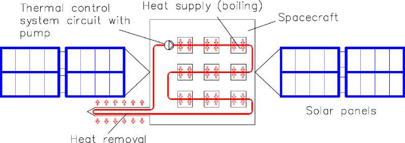
(condensation)
Рис. 1. Контур двухфазной системы терморегулирования
Fig. 1. Two-phase thermal control system circuit
Due to the specific nature of heat exchange in the circuit, the number of control points for parameters such as thermal loads, surface temperatures of heat exchangers, steam temperature, liquid temperature, radiator temperature, flow rate, pressure and pressure of the pump increases significantly.
Thermodynamic processes of heat supply and removal in this case occur with a change in the phase state of the working fluid, which determines the list of difficulties in calculating TPHC. At present, the issue of heat exchange during phase transitions of the coolant has not been sufficiently studied.
Due to the significant interest in two-phase flows, many experiments have been conducted to study heat exchange processes in them. However, the presence of many research papers has led to a significant differentiation of research methods, terminology and calculation approaches. A review of modern methods has shown that at present there is a lack of research to determine the thermodynamic parameters at the initial stages of boiling, especially at a low degree of dryness [8; 9]. The study of the calculation and schematic constructions of two-phase contour systems showed that most of the time the equipment operates under variable load.
In the movement of two-phase flows in heat exchangers, continuous and dispersed phases are distinguished. The latter is distributed in the continuous phase. The main task of the engineering calculation of the hydrodynamics of two-phase systems is to determine the volume content and linear velocity of the phases. The design characteristics of the devices through which the two-phase flow occurs have a significant impact on its state [10; 11]. Therefore, the hydrodynamic analysis of two-phase systems cannot be separated from the analysis of the design features of the devices, which determines the importance of an integrated approach in this area of research.
Description of the experimental setup
Figure 2 shows the pneumohydraulic diagram (PHD) of the setup for ground-based experimental testing of the TCS TPHC.
The setup consists of two closed circuits:
-
– circuit A, designed to circulate the working fluid. This circuit replicates the TCS circuit in geometric and thermal parameters and includes a circulation pump, receiver, heat exchangers for boiling and condensing the coolant;
-
– circuit B, which is a simulator of the spacecraft’s devices’ thermal load and consists of a pump, boilers, and a receiver.
Heat is transferred between the circuits in the evaporator block in heat exchangers TA1-TA6. A condenser block is used to cool and condense the working fluid of circuit A, including a heat exchanger 6 with forced air cooling by four fans 8–11 .
Expansion tank 12 and circulation pump 13 are responsible for the circulation, accumulation and regulation of the working fluid in circuit A, and expansion tank 4 and circulation pump 5 in circuit B. Heat is supplied to circuit B in the heater unit using flow-through electric heating boilers EVAN 1 and 2 . The capacity of the boilers used in the installation is 10 kW each.
To regulate and control the flow parameters of the coolant in the circuits, corresponding blocks 3 and 14 are provided, consisting of a pressure gauge a , a flow meter b and a regulating valve c . The temperature of the coolant is measured using thermocouples T1-T17.
The experimental setup allows for visual recording of the structure of the two-phase flow at the outlet of the heating sections to be performed due to the installation of transparent inserts. This feature is the key to the developed stand and allows for an assessment of the structure of the two-phase flow, the speeds of the phases to be performed.
For safety reasons, water is used as a heat carrier (the stand is located in the educational and scitific laboratory of Reshetnev Siberian State University of Science and Technology). Based on the technical limitations of the heating circuit (the maximum heating temperature of electric boilers is up to 90 °C, temperature losses along the pipeline), at these temperature values, in order to create the possibility of a phase transition of the heat carrier, it is necessary to reduce the pressure in the closed measuring circuit to a value of 0.3 to 0.5 atm, which is ensured by a vacuum pump [12; 13]. The developed measurement system allows monitoring the following parameters of the circuit: the temperature of the working fluid, the heat carrier and the wall surface, the volumetric flow rate of the working fluid and the heat carrier [12; 13].
The developed measurement system allows monitoring the following parameters of the circuit operation: temperature of the working fluid, coolant and wall surface, volumetric flow rate of the working fluid and coolant.
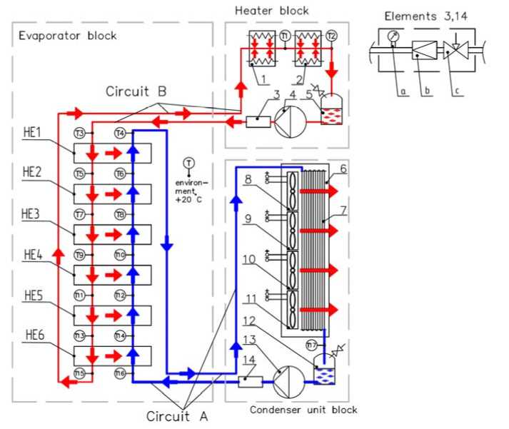
Рис. 2. ПГС стенда для наземной экспериментальной отработки ДФК СТР:
1 и 2 – электрокотел ЭВАН 10 КВт; 3 и 14 – блок измерения и регулирования;
4 и 13 – циркуляционные насосы; 5 и 12 – расширительный бак; 6 – радиатор конденсатора;
7 – теплообменная поверхность радиатора; 8–11 – вентиляторы принудительного охлаждения
-
Fig. 2. Pneumatic-hydraulic system of the stand for ground experimental testing of a two-phase circuit:
-
1 , 2 – electric boiler EVAN 10 kW; 3 , 14 – measurement and control unit; 4 , 13 – circulation pumps;
-
5 , 12 – expansion tank; 6 – condenser radiator; 7 – heat exchange surface of radiator;
8–11 – forced cooling fans; HE1– HE6 – heat exchangers
The experimental setup can operate in the following ranges of operating parameters: working fluid temperature from +20 to +90 °C; working fluid pressure from 0.016 to 3.04 MPa; working fluid flow rate from 0.5 to 4 l/min; coolant flow rate from 2 to 16 l/min; consumed electric power from 1 to 30 kW; temperature in the climatic chamber from –40 to +20 °C. According to these operating parameters, the setup meets the objectives of thermal ground experimental development of two-phase TCS with pump circulation of coolant with a capacity of more than 10 kW at the stage of research and development work.
Use of climatic chamber in the experimental setup
To be able to conduct experimental studies under conditions of circuit operation at negative temperatures (simulation of operating conditions of unsealed spacecraft during GET), a climatic chamber with a refrigeration unit was introduced into the experimental setup. The pneumatic-hydraulic diagram of the rig for ground-based experimental testing of the TPHC TCS SC with a climatic chamber is shown in Fig. 3. The temperature regime inside the chamber is maintained using a compressorcondenser monoblock.
The setup consists of three closed circuits: circuit C is added to circuits A and B from the previous diagram, which is the circuit of the refrigeration machine and includes compressor 25 , air cooler 18 , condenser 26 and expansion valve 32.
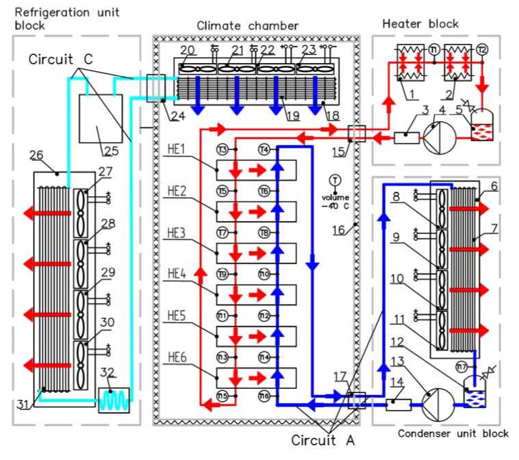
Рис. 3. ПГС стенда для наземной экспериментальной отработки ДФК СТР КА с климатической камерой:
1 и 2 – электрокотел ЭВАН 10 КВт; 3 и 14 – блок измерения и регулирования; 4 и 13 – циркуляционные насосы; 5 и 12 – расширительный бак; 6 – радиатор конденсатора; 7 – теплообменная поверхность радиатора; 8–11 – вентиляторы принудительного охлаждения; 15 , 17 и 24 – соединительные каналы; 16 – стенка камеры;
18 – воздухоохладитель; 19 – теплообменная поверхность воздухоохладителя; 20–23 – вентиляторы воздухоохладителя; 25 – компрессор; 26 – конденсатор холодильной установки; 27–30 – вентиляторы конденсатора холодильной установки; 31 – теплообменная поверхность конденсатора холодильной установки; 32 – расширительный вентиль
-
Fig. 3. Pneumatic-hydraulic system of the stand for ground experimental testing of the two-phase circuit with a climatic chamber:
-
1 , 2 – electric boiler EVAN 10 kW; 3 , 14 – measurement and control unit; 4 , 13 – circulation pumps;
-
5 , 12 – expansion tank; 6 – condenser radiator; 7 – heat exchange surface of radiator; 8–11 – forced cooling fans;
-
15 , 17 , 24 – connecting channels; 16 – chamber wall; 18 – air cooler; 19 – heat exchange surface of air cooler; 20–23 – air cooler fans; 25 – compressor; 26 – condenser of refrigeration unit; 27–30 – condenser fans of refrigeration unit; 31 – heat exchange surface of condenser of refrigeration unit; 32 – expansion valve; HE1–HE 6 – heat exchangers
In this case, the main circuit is placed in a climatic chamber - a heat-insulated volume that provides a temperature below the ambient temperature. In this form, the experimental setup allows for a temperature in the climatic chamber of up to –40 °C. Providing a lower temperature level is possible using cascade cooling schemes.
Testing Methodology
A testing methodology was developed for testing on the developed experimental stand for the GET TPHC TCS. It includes a testing algorithm and a description of the software and hardware for testing. The software and hardware for testing include electronic means for measuring the main parameters of the operating modes of the TPHC TCS and an automated test process control system [14; 15]. The fol- lowing electronic measuring instruments are used in the rig: for measuring temperature - thermocouples of the OWEN DTPK011 type with a measurement range from –40 to +300 °C; for measuring pressure diaphragm pressure sensors of the OWEN PD100 type with a measurement range of 0.016 to 100 MPa are used; for flow measurement FLOW SWITTCH PF2W504-F03 turbine volume flow meter with a measurement range from 0.5 to 4 l/min for circuit A and FLOW SWITTCH PF2W520-F03 turbine volume flow meter with a measurement range from 2 to 16 l/min for circuit B is used. Parameters for the experimental rig for GET TPHC TCS are the following: power consumption from 1 to 30 kW; pressure in circuits A, B and C from 0.015 to 3.04 MPa; temperature in circuits A, B and C from –40 to +300 °C.
The automated test process control system is based on the use of programmable logic controllers. To automate the operation of the installation, the stand uses the OWEN PLC200 controller – a monoblock controller with discrete and analog inputs/outputs, designed to monitor and control the operating modes of small systems. The system operates using the CODESYS (Controller Development System) application development environment for programmable logic controllers. The automated testing process control system based on OWEN controllers and the CODESYS complex is shown in Fig. 4.
Computer with software CODESYS V3.x
LAN1
Ethernet-switch
Ethernet—server
124 volts |
J LAN 2
LAN 0 .------------.
| 24 volts |
PLC200-04-CS
Extension module MB210—101
| Input analoi
Out, digital |ln. digit. |
CM
P1 P2 M1 М2
| 220 voltsl
|380 volts |
Refrigerating chamber
|220 volts |
Fan 1
cont.unit2^
|220 volts |
О
I
CM
I
Input analog
Ф Ю CD Г^ 00
Extension module MB210—101
Fan 3
Fan 4
Input analoq
Illi г
Fan 1| m Fan 3 Fan 4
Converter 4 cont.unit3
Г- Converter
|Fqn~f
Fan 3
^Fan 4
111 112 113 114 US Tie 117 TIB 1H 120
Рис. 4. Автоматизированная система управления процессом испытаний на основе контролеров OWEN и комплекса CODESYS
-
Fig. 4. Automated testing process control system based on OWEN controllers and the CODESYS complex
Nowadays, CoDeSys is the most common hardware-independent application software development complex for programmable logic controllers (PLCs) and embedded controllers. The central element of this system is the software environment developed using languages that comply with the IEC 61131-3 standard.
The measuring system is built on the basis of PLC200-04-CS controllers, according to the diagram in Fig. 4. The process of reading and registering parameters is carried out in the graphical development CODESYS. When the program starts, configuration files are loaded, which contain a detailed description of the measuring channels, after which the general measurement cycle is immediately initiated [13].
The experiment is carried out in several stages, the purpose of which is to obtain the main parameters of the boiling working fluid in small-diameter pipes with visual confirmation of the structure of the two-phase flow. The flow chart of the testing algorithm is shown in Fig. 5
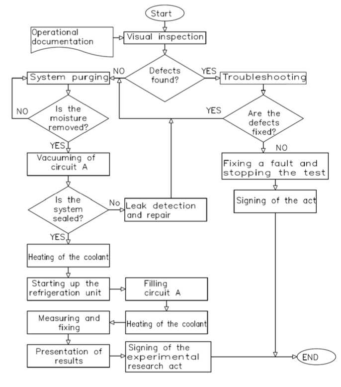
Рис. 5. Блок-схема алгоритма проведения испытаний
Fig. 5. Block diagram of the testing algorithm
Before testing, a visual inspection of the unit is carried out to determine its operability and eliminate possible defects. At the next stage of the GET, circuit A is purged with air to remove moisture for 3 hours. After purging, the circuit is evacuated and its tightness is checked for 1 hour.
At the next stage, the circulation pump of circuit B (heat load simulator) is started, the boiler is started, and the unit is heated to a temperature of 70 °C.
Then, the refrigeration unit is started, and work is carried out to fill circuit A with hot coolant from circuit B until the specified pressure is reached.
At the next stage of system startup, the coolant of circuit A is heated to the specified temperature. Upon completion of this stage, the stand is ready to conduct tests of the TPHC TCS in accordance with the specified test program. Measurement and recording of parameters are performed automatically.
This algorithm was successfully tested during tests of TPHC TCS in the conditions of the educational and scientific laboratory of Reshetnev Siberian State University of Science and Technology. Currently, work is underway to summarize the obtained test results and develop practical recommendations for the design of the spacecraft TPHC TCS SC.
Conclusion
The developed experimental setup for conducting studies of two-phase spacecraft thermal control systems is a climatic chamber for simulating real operating conditions of elements in the negative temperature range and includes three circuits: a coolant pumping circuit corresponding in parameters to the studied thermal control system, a cooling system circuit and a thermal load simulator circuit. Electric heating elements are used as a thermal load simulator. The bench measurement system allows monitoring the parameters of temperature, pressure and flow at various points in the circuit. Transparent inserts provide the ability to visually control the structure of the two-phase flow during boiling and assess the volumetric content of the vapor phase.
A test procedure was developed for the considered setup, including a test algorithm and a description of the software and hardware for testing. The software and hardware testing tools include electronic measuring tools for the main parameters of the operating modes of the TPHC TCS and an automated testing process control system based on OWEN controllers and the CODESYS complex. The results obtained in the work can be used in planning and implementing the GET TPHC TCS SC programs, in developing ground test stands for conducting studies of spacecraft systems.
References Development of an experimental unit and methodology for groundbased experimental testing of two-phase thermoregulation systems for spacecrafts
- Patrayev V. Ye. [Ground-based experimental testing of the Yamal-300K spacecraft based on a qualified platform]. Vestnik SibGAU. 2010, No. 2, P. 97–101 (In Russ.).
- Dvirny V. V., Krushenko G. G., Dvirny G. V., Shevchuk A. A., Elfimova M. V., Kuznetsova M. S. [Features of spacecraft thermal control system components]. Kosmicheskiye apparaty i tekhnologii. 2019, No. 1 (27), P. 13–21 (In Russ.).
- Shatrov A. K., Rabetskaya O. I., Fisenko Ye. N. [Ensuring thermal conditions for spacecraft structures]. Sibirskiy aerokosmicheskiy zhurnal. 2023, Vol. 24, No. 3, P. 550–557 (In Russ.).
- Krat S. A., Khristich V. V. [Thermal vacuum testing of spacecraft: development of new trends]. Vestnik SibGAU. 2010, No. 4, P. 126–129 (In Russ.).
- Yi-Gao L., Yao-Ting W., Tong M., Qiu-Wang W., Wen-Xiao C. Review on thermal management technologies for electronics in spacecraft environment. Energy Storage and Saving. 2024, Vol. 3 (3), P. 153–189. DOI: 10.1016/j.enss.2024.03.001.
- Dmitriev G. V., Shilkin O. V., Kolesnikov A. P., Dvirny V. V., Sidorova E. S. [Application of heat exchangers in a two-phase circulation system during ground testing of spacecraft]. Kosmicheskiye apparaty i tekhnologii. 2014, No. 4 (10), P. 21–27 (In Russ.).
- Meng Q., Zhang T. Experimental study on dynamic behavior of mechanically pumped twophase loop with a novel accumulator in simulated space environment. Chinese Journal of Aeronautics. 2022, Vol. 35, Iss. 2, P. 102–116. DOI: 10.1016/j.cja.2022.06.004.
- Xiao Q., Han X., Wang J., Zhou Y., Liu C., Zhang L. Research on thermal control technology of space station complex based on fluid-structure coupling. 2020 7th International Forum on Electrical Engineering and Automation (IFEEA). Hefei, China, 2020, P. 801–805. DOI: 10.1109/IFEEA51475.2020.00168.
- Gorbenko G., Gakal P., Turna R., Hodunov A. Retrospective Review of a Two-Phase Mechanically Pumped Loop for Spacecraft Thermal Control Systems. Journal of Mechanical Engineering. 2021, No. 24, P. 27–37. DOI: 10.15407/pmach2021.04.027.
- Khodenkov A., Khodenkova E. The heat transfer processes mechanism during coolant boiling in pipes of small diameter. AIP Conference Proceedings. Melville, New York, United States of America, 2021, P. 60026.
- Khodenkov A., Khodenkova E., Delkov A., Melkozerov M. Method for calculating heat transfer boiling parameters based on the combined effect of convective and nucleate boiling processes. AIP Conference Proceedings. Melville, New York, United States of America, 2021, P. 60034.
- Khodenkov A. A., Vasilyeva Ye. K., Zhilinskiy A. I. [Thermal closed loop for experimental study of the boiling process]. Materialy XXIV Mezhdunarodnoy nauchno-prakticheskoy konferentsii Reshetnevskiye chteniya [Materials XXIV Intern. Scientific. Conf “Reshetnev reading”]. Krasnoyarsk, 2020, P. 184–185 (In Russ.).
- Vasilyeva Ye. K., Khodenkov A. A., Zhilinskiy A. I. [Temperature sensors for an automated data recording system]. Materialy XXIV Mezhdunarodnoy nauchno-prakticheskoy konferentsii Reshetnevskiye chteniya. [Materials XXIV Intern. Scientific. Conf “Reshetnev reading”]. Krasnoyarsk, 2020, P. 186–187 (In Russ.).
- Ivanov V. I., Shvets D. A., Lekanov A. V., Baranov V. V. [Hardware and software for ground tests of spacecraft units and mechanisms]. Zhurnal Sibirskogo federal'nogo universiteta. Tekhnika i tekhnologii. 2012, No. 2 (5), P. 169–178 (In Russ.).
- Gusenitsa Ya. N. [Methodology for assessing the quality indicators of an object during a limited amount of testing]. Izvestiya Tulskogo gosudarstvennogo universiteta. Tekhnicheskiye nauki. 2022, No. 3, P. 491–497 (In Russ.).
