Development of automatic system for Unmanned Aerial Vehicle (UAV) motion control for mine conditions
 motion control for mine conditions")
Author: M. L. Kim, L. D. Pevzner, I. O. Temkin
Journal: Горные науки и технологии @gornye-nauki-tekhnologii
Section: Энергетика, автоматизация и энергоэффективность
Article in issue: 3 т.6, 2021.
Free access
Underground mining operations are connected with significant risks of technogenic accidents, which can be catastrophic. Mitigating the consequences of such phenomena directly depends on the reliability and efficiency of information about the state of parameters of many technological processes, mine workings and facilities located in them. At failure of standard systems of industrial telemetry in conditions of underground mining the creation of new information channels and places of information measurement becomes practically impossible in case of emergency situation development. This predetermines necessity of use of essentially new systems of gathering and transfer of the information, based on robotized autonomous complexes. The task of acquiring reliable information about the situation in an emergency mine working with the help of drones (unmanned aerial vehicles or UAV) in order to make rational decisions in the course of the rescue operation is quite relevant. The aim of the paper was to develop a system of automatic control of an unmanned aerial vehicle (UAV) movement in confined space of a mine working, with significant perturbations of the mine air flow. The mathematical model of UAV movement in mine conditions, based on Euler angles or quaternions, was substantiated. The method of positioning through triangulation with the use of radio beacons was accepted as the basic method that allowed to determine the current position of an UAV. It was proposed to solve the problem of creation of the automatic system for an unmanned aerial vehicle movement control with the use of a hierarchical multiloop control system. The route planning algorithm was formed on the basis of the Dijkstra algorithm. For this purpose, discretization of the future motion space was performed, a labeled connected graph was constructed, on which the arc weights were the distances between the route points. A simulation experiment was implemented. The average deviation from the planned trajectory when flying at a speed of 10 m/s with payload mass up to 0.6 kg did not exceed 1 m, and the maximum deviation was unacceptably large. When flying at 6 m/s with payload mass up to 0.6 kg the average deviation did not exceed 0.3 m, and the maximum deviation, 1.2 m. The results of simulation of movement along the route towards the disturbing mine airflow showed that the control system allowed the UAV with payload of 0.6 kg to withstand the oncoming flow up to 8 m/s. It was obtained that with payload mass of 0.6 kg, the braking distance does not exceed 6 m if the UAV had a speed of 6 m/s, and the braking distance does not exceed 12 m at the speed of 10 m/s. The performed simulation studies confirmed the operating capability of the developed system for automatic motion control.
Mine workings, mine conditions, accidents, unmanned aerial vehicle, drone, mathematical model, control, coordinates, simulation
Short address: https://sciup.org/140259852
IDR: 140259852 | DOI: 10.17073/2500-0632-2021-3-203-210
Разработка системы автоматического управления движением БПЛА с учетом шахтных условий
Ведение подземных горных работ сопряжено со значительными рисками техногенных аварий, которые могут носить катастрофический характер. Снижение последствий таких явлений напрямую зависит от достоверности и оперативности информации о состоянии параметров многих технологических процессов, горных выработок и объектов, в них расположенных. При выходе из строя штатных систем производственной телеметрии в условиях подземных горных работ создание новых информационных каналов и мест измерения информации становится практически невозможным при аварийном развитии ситуации, что предопределяет необходимость использования принципиально новых систем сбора и передачи информации, основанных на роботизированных автономных комплексах. Задача получения достоверной информации об обстановке в аварийной горной выработке с помощью беспилотных летательных аппаратов с целью принятия рациональных решений при ведении спасательной операции является актуальной. Целью статьи является разработка системы автоматического управления движением беспилотного летательного аппарата (БПЛА) в условиях ограниченного пространства горной выработки, при значительных возмущениях шахтного воздушного потока. Обоснована математическая модель движения БПЛА в шахтных условиях, основанная на углах Эйлера или кватернионах. Основным методом, позволяющим определять текущее положение летательного аппарата, принимается метод позиционирования с использованием радиомаяков путем триангуляции. Задачу синтеза системы автоматического управления движением беспилотного летательного аппарата предлагается решать с использованием иерархической многоконтурной системы управления. Алгоритм планирования маршрута сформирован на основе алгоритма Дейкстры. Для этой цели выполняется дискретизация пространства будущего движения, строится помеченный связный граф, на котором весами дуг являются расстояния между точками маршрута. Реализован модельный эксперимент. Среднее отклонение от запланированной траектории при полете на скорости 10 м/с при массе полезной нагрузки до 0,6 кг не превышает 1 м, а максимальное отклонение – недопустимо большое. При полете на скорости 6 м/с при массе полезной нагрузки до 0,6 кг среднее отклонение не превышает 0,3 м, а максимальное отклонение – 1,2 м. Результаты моделирования движения по маршруту навстречу возмущающему шахтному воздушному потоку показали, что система управления позволяет БПЛА с полезной нагрузкой 0,6 кг выдерживать встречный поток до 8 м/с. Получено, что при массе полезной нагрузки 0,6 кг тормозной путь не превышает 6 м, если летательный аппарат имел скорость 6 м/с, и тормозной путь не более 12 м при скорости движения 10 м/с. Проведенные модельные исследования подтверждают работоспособность разработанной системы автоматического управления движением.
Text of the scientific article Development of automatic system for Unmanned Aerial Vehicle (UAV) motion control for mine conditions
Conducting underground mining operations is connected with significant risks of technogenic accidents, which can be catastrophic. Mitigating the consequences of such phenomena directly depends on the reliability and efficiency of information about the state of parameters of many technological processes, mine workings and facilities located in them. At failure of standard systems of industrial telemetry in conditions of underground mi- ning the creation of new information channels and places of information measurement becomes practically impossible in case of emergency situation development. This predetermines necessity of use of essentially new systems of gathering and transfer of the information, based on robotized autonomous complexes [1–4]. The task of acquiring reliable information about the situation in an emergency mine working with the help of drones (unmanned aerial vehicles or UAV) in order to make rational
ГОРНЫЕ НАУКИ И ТЕХНОЛОГИИ https://mst.misis.ru/
2021;6(3):203–210 Kim M. L. et al. Development of automatic system for Unmanned Aerial Vehicle...
decisions in the course of the rescue operation is quite relevant. The aim of the paper was to develop a system of automatic control of an unmanned aerial vehicle (UAV) movement in confined space of a mine working, with significant perturbations of the mine air flow, and taking into account other factors.
Technological solutions related to UAV operation in underground mine workings exist [5, 6]. They envisage performing a number of specific functions: determining the condition of mine workings, measuring parameters of the mine atmosphere, delivery of life-support equipment to miners who find themselves in an emergency situation. These developments also envisage creation of autonomous control systems for UAVs based on artificial intelligence algorithms, allowing to perform assigned tasks taking into account the mine plan, condition of mine workings, technological processes and mine atmosphere. The solution of such a class of problems requires more detailed elaboration in terms of formalization of systems for automatic control of UAV movement in mine conditions.
1. Mathematical model of UAV movement in mine conditions
The mathematical model of UAV motion as a control object was formed on the basis of the computational scheme (Fig. 1), in which a four-engine unmanned aerial vehicle was considered as a solid body with known [7] aerodynamic properties and assumptions.
The spatial positioning of the UAV was performed in a stationary { Ж } = { O 0 , X 0 , Y 0, Z 0 } - inertial coordinate system associated with some fixed point of the mine workings.
The moving coordinate system { S } = { O , X , Y , Z } -cent e red in the center of mass of the uAv, shifted by vector V relative to the global coordinate system, has axes pointing along the main axes of the UAV as a solid body. This coordinate system has an inertia tensor in the form of a diagonal matrix.
To describe an UAV movement in space, the coordinates { x, y, z } in the stationary system and the Euler angles { ϕ , θ , ψ } — roll, pitch and yaw, respectively, in the moving coordinate system were used.
The description of the UAV motion mathematical model, performed in the reference frame S , takes the form [8]:
' J 1 ™ 1 '
J 2( O 2
v J 3 № 3 j
' ( J 2 - J . ) №№■ + M/ ( J 3 - J 1 ) Ю 1 Ю 3 + M 2 v ( J 1 - J 2 ) ю 2 ю 1 + M 3 j
where Ji – axial moments of inertia; ω i – angular velocities; Mi – m om entum of forces acting on the UAV along the axes i = 1,3.
The UAV has 6 degrees of freedom: three angles ( ϕ , θ , ψ ) and three coordinates of the center of mass ( x, y, z ). Thus, the UAV motion is determined by 12 states:
D = ( x , y , z ), E = ( ф , 0 , у ),
D = ( x У , z ), E = ( Ф , 0 , У )
The motion of a solid can be described by three methods: rotation matrices, Euler angles, or quaternions.
The quaternion method is the most efficient: it is compact, because it uses four parameters instead of nine for the matrix method, it has no singularities and no trigonometric functions when converting vectors (unlike the Euler method).
The kinematics of the angular coordinates of an UAV in terms of quaternions Q is described by the following equation:
|
^ 0 -w 1 -™ 2 -w 3 ' |
||
|
■ |
to, 0 to, -ton |
|
|
Q = 0,5 |
1 32 |
Q , |
|
to 2 -to 3 0 № 1 |
||
|
V® 3 № 2 -№ 1 0 J |
(2) |
Q = ( q o , qv q 2 , q 3)T .
The UAV is affected by lifting forces F j , j = 1,4 from each propeller, gravity force G = mg, viscous frictional forces, external forces of resistance to motion N = ( N x Ny Nz ) T . The equations of motion according to Newton’s law for a solid body in the global coordinate system take the form:
x
( 0 )
( 0 )
x
/
y ; = Q 0 QT + 0 + k r y
■ • z
V a j
v g 2
v z J
— m
v
N x )
N y
N z J
, (3)
where m – mass of the UAV; g – acceleration of free fall; kr – coefficient of proportionality of the viscous friction force; a - total thrust of four propellers; N = ( N x Ny N z ) T / m -reduced forces of resistance to motion.
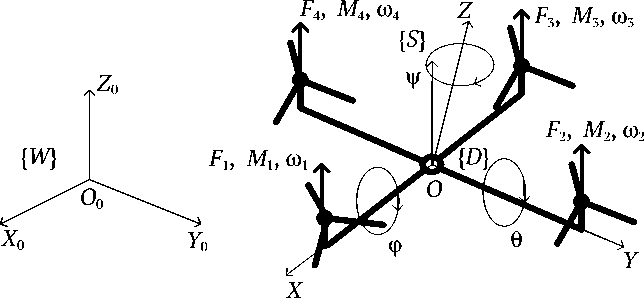
Fig. 1. Unmanned Aerial Vehicle Computational Model
ГОРНЫЕ НАУКИ И ТЕХНОЛОГИИ https://mst.misis.ru/
2021;6(3):203–210 Kim M. L. et al. Development of automatic system for Unmanned Aerial Vehicle...
The four UAV motors create an aerodynamic force, which, according to the formula of N.E. Zhukovsky [9], is defined for each j -th propeller as:
F j = C f p r 2 « j S , j = 1,4, (4) where ω j is the rotation frequency of the j -th propeller, cF is the thrust factor which depends on the propeller shape; ρ is the air density; r, S are the rotor radius and the propeller disk area respectively.
The main vector of lifting force — the total thrust vector — is equal to:
ultrasonic triangulation is also unsuitable for this task, since the mine workings have a nontrivial topology.
The method of positioning through triangulation with the use of radio beacons was accepted as the basic method that allowed to determine the current position of an UAV. This method makes it possible to achieve an accuracy of up to a few centimeters, which is an order of magnitude smaller than the size of the UAV. Thus, the position measurement error can be neglected and the exact position of the UAV can be used in the simulation process.
I 4
F = 0 0 £ F j
I j = 1
T
The axial moments of rotation — the projections of the main moment on the corresponding axes of the moving coordinate system — are determined from the expressions:
M x = ( F 2 - F 4 ) L ,
M y = ( F 3 - F 1 ) L ,
M Z = M 1 + M 3 - M 2 - M 4,
where L is the distance between the center of mass and the propeller axes.
The thrust vector and axial moments are the control actions to form the UAV motion:
u 1 = F , u 2 = M X , u3 = M Y , u 4 = M Z . (7)
The control actions proportional to the square of the propeller rotation frequency are formed by brushless direct current electric motors of independent excitation, the mathematical model of which is represented as a linear dynamic element of the second order.
An integral part of the mathematical model of the UAV motion is the model of the external environment, the main factors of which are constraints in the spatial movement of the UAV and external disturbing influences.
To implement spatial constraints, the method of penalty functions in the form of an exponential “barrier” is used, which sets the potential acting on the object, whose value in the area where movements are allowed is zero, and in the forbidden zone exponentially increases depending on the distance to the constraining boundary, for example, according to the relation
Fc (d) = Fo(e“d2 -1), where d – distance from the UAV to the forbidden area boundary; α – tunable parameter.
When simulating the motion of an unmanned aerial vehicle, it was assumed that its position in space was known accurately enough. The task of current positioning of an UAV can be solved by optical odometry, tag-based positioning, local positioning system based on RFID, audio tag-based positioning, and SLAM method, used in mobile autonomous vehicles to build a map in unknown space with simultaneous control of current position and distance covered.
In mine conditions, especially in post-accident conditions, when visibility deteriorates significantly, the use of visual methods becomes impossible. Positioning using
2. Automatic control system for UAV routing
The current position of an UAV in space is determined by six coordinates: three spatial coordinates of the moving center of mass ( x ( t ), y ( t ), z ( t )) in the stationary coordinate system, and three angular coordinates ( ϕ ( t ), θ ( t ), ψ ( t )) in the moving coordinate system. The trajectory to be set for the forthcoming motion of the UAV is formed as a function of time in the natural coordinates:
r ( t ) = R ( X d ( t ), y d ( t ), Z d ( t )). (8)
It was proposed to solve the problem of creation of the automatic system for an unmanned aerial vehicle movement control, according to [10, 11], with the use of a hierarchical multiloop control system with the structure shown in Fig. 2.
In the presented system, block 1 is the route planner designed to form a trajectory of the route to the target at any given moment of time and adjust it with the appearance of obstacles.
r d ( t ), r d ( t )


^ 3
^ 4
3 5
r(t ), Г(t )
Fig. 2. Structure of automatic UAV trajectory control system
Block 2 of the structure is the block of control of the UAV position in space; it controls the UAV linear coordinates in order to keep it along the planned trajectory of movement.
Block 3 of the structure is the block for controlling the angular position of the UAV; it allows to maintain the required values of quaternions.
Block 4 of the structure is a motor control block, which forms the control actions on the motor windings and allows the formation of the required thrust force of the UAV.
Each block of the system structure, with the exception of the planner block, is linear with a feedback loop and digital PID controller [12]. The control system structure turns out to be in a sense similar to that of a slave control system.
Noises and delays of signals arising in real conditions in the “sensors” for determination of angular orientation and location in the fixed coordinate system, used to form feedbacks in the control system, were not taken into account in the simulation.
ГОРНЫЕ НАУКИ И ТЕХНОЛОГИИ https://mst.misis.ru/
2021;6(3):203–210 Kim M. L. et al. Development of automatic system for Unmanned Aerial Vehicle...
External disturbing influences — forces of resistance to motion, are generated by air flows, the vector of which can be directed counter, orthogonal or along the direction. In the mathematical model of an UAV motion, these disturbing influences are specified in the form of known functions of time in the right-hand sides of the equations of motion.
The necessary changes in the angular position of the UAV are achieved by changing the rotation frequency of the propellers and, as a consequence, by changing the lifting forces and moments. The task of controlling the angular position of an UAV is to maintain the required angular position of the UAV.
The structure of block 3, where the problem of controlling the angular position of the UAV is solved, is shown in Fig. 3. The structure contains: 3.1 – gyroscope unit; 3.2 – accelerometer unit; 3.3 – gyrostabilizer IMU unit; 3.4 – converter of quaternions into Euler angles; 3.5 – unit of desired angles of UAV position with input from block 2; 3.6 – PID controller; 3.7 – converter of angular accelerations into motor speed; 4 – motor control block.
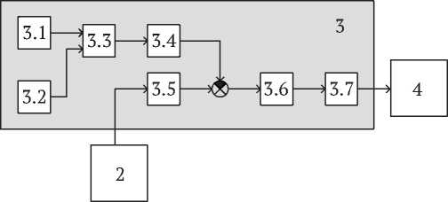
Fig. 3. Structure of UAV angular position control block
The IMU software module is used to determine the angular position of an UAV [13]. It is known that the description of gyroscope and accelerometer operation is more convenient in the quaternionic representation. The IMU module allows UAV to position itself in space without the use of external sensors. The output signal from this module is a four-dimensional vector of angular position of the UAV in quaternion representation. Block 3.4 converts the quaternions into Euler angles [14].
The resulting three-dimensional vector, which characterizes the current angular position of the UAV, allows to determine the angular position error by comparing it with the required angular position of the UAV, which is dictated by the trajectory planner from block 1. The error signal goes to the PID controller, where the control signal is formed and sent to the conversion unit 3.7, where the motor rotary speed setting signals are formed.
In the UAV angular position control block, a linearized model of equations (6) was used, in the form of:
Equations (9) represent three equations relative to the four unknown lifting forces Fi , so to unambiguously determine all components of the thrust vector of the motors, we should use the equation of dynamics along the z-axis:
mr3 (t) = X F — mg cos a, i=1
where α is the angle of inclination of the UAV relative to the vector of gravity.
Denoting mr3(t) + mg cos a
B = 4 , we obtained, by transforming equations (8), the basic relations on the required thrust of the engines:
F 1 = B + (b i + cb 2 + cb з ,
F 2 = B + cb 1 — cb 2 — cb 3 ,
F 3 = B — b 1 — cb 2 +cb 3 , (10)
F 4 = B — cb 1 + cb 2 — cb 3 .
3. Control of UAV spatial position
The problem of controlling an UAV position in space is solved by determining r d ( t ), the required inclination angle of the UAV. In order to keep the UAV altitude at the required level, the thrust of all motors must be equal to
X F i = F .
i =1
To move in the horizontal plane, it is necessary to set such ϕ , θ (pitch and roll angles) so that the projection of the thrust vector F on the horizontal plane is directed to the target point. Thus, at each moment of time, knowing the required angular acceleration r d ( t ), the required pitch and roll angles ϕ d ( t ), θ d ( t ) should be determined.
To keep the UAV position in the vicinity of the desired angles, a linear PD controller was synthesized, which formed a control vector based on εϕ , εθ , εψ – the current angular errors of the UAV position.
The PD -controller parameters were determined by minimizing the quadratic functional from the angular errors and their derivatives.
Planning UAV trajectory route
The route planning algorithm implemented in Block 1, the route planner of the system, is based on the Dijkstra algorithm [15]. For this purpose, discretization of the future motion space was performed, a labeled connected graph was constructed, on which the arc weights were the distances between the route points. The target point of movement is set by mobile stations SBGPSMaster-06-WRM (base stations “GRANCH”), located along the route of UAV movement every 100 m; in this case several variants of routing to the target point are possible.
The found route is a piecewise linear continuous curve, which does not have the required smoothness in conjunctions. The required smoothness property is provided by spline approximation of the curve.

MINING SCIENCE AND TECHNOLOGY (RUSSIA) ГОРНЫЕ НАУКИ И ТЕХНОЛОГИИ
eISSN 2500-0632
2021;6(3):203–210
Kim M. L. et al. Development of automatic system for Unmanned Aerial Vehicle...
After generating the splines and setting the current speed, time dependences of the required coordinates, speeds and accelerations are generated. These functions are sent to the coordinate controller, where the relations (8) are implemented.
4. The motion control system simulation studies
Experimental computer simulation of the flight control process along the given trajectory, taking into account spatial constraints in mine workings and the mine airflow disturbances, was performed using SimInTech software [16].
For the computer simulation, parameters of the UAV with a span of 0.36 m, a mass of 0.65 kg, a matrix of axial moments of inertia J = diag (0.002352 0.002352 0.004704) kgm/s2 were used.
The drives of the propellers are DC motors X2212 KV980 with a linear char ac teristic of the frequency of rotation го i = 102,6 uM , i = 1,4 as a function of the supply voltage uM , which takes values from 0 to 15.4 V. The UAV storage batteries of 330W have capacity of 4000 mAh. The developed mathematical model of an UAV as a controllable object is represented by a system of ordinary nonlinear differential equations with restrictions on the permissible range of motion, which reflects the spatial limitations of motion in the conditions of mine workings, and perturbations reflecting the impact of mine air flows [17].
At the first stage of the numerical simulation, the optimum parameters of the PD -controller of the the UAV spatial position control block and the UAV angular position control block were selected. Since a linear algorithm is used in these blocks, linearization of the equations was performed to select the coefficients of the algorithm, followed by the calculation of the coefficients of the controller algorithm, optimal in terms of the quadratic functional of the tracking error and its derivative over time, by numerical solution of the Riccati matrix equation.
At the second stage of the research experiment, simulation of the guided motion of UAV with different weight load in the presence of disturbances in the form of mine air flows and various obstacles was carried out.
To form the motion route, a fragment of mine workings system of “Mine named after V.D. Yalevsky” of JSC SUEK-Kuzbass was used, shown in Fig. 4, a , where the main markers of the supposed route of the UAV, the motion direction, the temperature at the nodal points, as well as the location of “GRANCH” base stations [4] are shown.
Based on the route prototype, a test polygon for the trajectory planner, shown in Fig. 4 , b , which contains the main features of the actual fragment of the topology of mine workings. When simulating, the velocity of the mine airflow was varied;
The UAV flight speed in the absence of disturbing air flow was taken constant of 6 m/s and 10 m/s.
Under these conditions, the following key simulation experiments were conducted:
– a flight over the test polygon without load, disturbances and obstacles;
– a flight without load, disturbance, but with obstacles;
– a flight without load, but with counter mine air flow;
– a flight with payload without air disturbances;
– a flight with at payload with counter mine air flow;
– an emergency flight braking with different payload.
5. The simulation study findings
In each of the experiments, the deviations of the actual trajectory from the planned trajectory were quantitatively recorded along all three axes, by which the mean deviation of the actual trajectory from the planned one and the maximum deviation of the actual trajectory from the planned one during the flight period were calculated.
Fig. 5, a, b presents the experimental curves reflecting the quality of control when flying the route, when the UAV was loaded or not loaded, when it flied at its maximum speed or at 60 % of it. The simulation of the motion in projection on the horizontal plane revealed undershooting in the x, y, z coordinates.
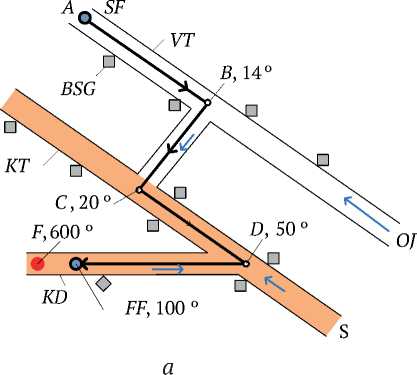
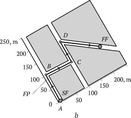
Fig. 4. a – fragment of mine workings of the Mine named after V.D. Yalevsky of JSC “SUEK-Kuzbass”, b – test polygon for the trajectory planner:
SF – flight start; FF – flight finish; F – fire; S – smoke; OJ – outgoing jet; VT – ventilation shaft; KT – conveyor shaft;
KD – conveyor drift; BSG – base stations “GRANCH”; A, B, C, D – points of trajectory bend and air temperature values in them
References Development of automatic system for Unmanned Aerial Vehicle (UAV) motion control for mine conditions
- Cunha F., Youcef-Toumi K. Ultra-wideband radar for robust inspection drone in underground coal mines. In: Proceedings – IEEE International Conference on Robotics and Automation. 2018. Pp. 86-92. https://doi.org/10.1109/ICRA.2018.8461191
- Dunnington L., Nakagawa M. Fast and safe gas detection from underground coal fire by drone fly over. Environmental Pollution. 2017;229:139–145. https://doi.org/10.1016/j.envpol.2017.05.063
- Annavarapu S., Kumar G. P. Development of drones to collect geotechnical data in large underground mines. In: Application of Computers and Operations Research in the Mineral Industry – Proceedings of the 37th International Symposium, APCOM 2015. 2015. Pp. 382–388.
- Green J. Mine rescue robots requirements: Outcomes from an industry workshop. In: Proceedings – 2013 6th Robotics and Mechatronics Conference, RobMech 2013. 2013. Pp. 111–116. https://doi.org/10.1109/RoboMech.2013.6685501
- Jones E., Sofonia J., Canales C., Hrabar S., Kendoul F. Applications for the Hovermap autonomous drone system in underground mining operations. Journal of the Southern African Institute of Mining and Metallurgy. 2020;120(1):49–56. https://doi.org/10.17159/2411-9717/862/2020
- Hennage D. H., Nopola J. R., Haugen B. D. Fully autonomous drone for underground use. In: 53rd U.S. Rock Mechanics/Geomechanics Symposium. Brooklyn, USA. 23 June 2019 – 26 June 2019.
- Belokon S. A., Zolotukhin Yu. N., Maltsev A. S., Nesterov A. A. et. al. Control of flight parameters of a quadrotor vehicle moving over a given trajectory. Avtometriya. 2012;48(5):32–41. (In Russ.). URL: https://sibran.ru/upload/iblock/587/587e1177954ed7b12e807ee43151e21a.pdf
- Zenkevich S. L., Yushchenko A. S. Manipulation robot control fundamentals. Мoscow: MSTU Publ.; 2004. 480 p. (In Russ.).
- Beard R. W., McLain T. W. Small unmanned aerial vehicles: theory and practice. Мoscow: TECHNOSPHERE Publ.; 2015. Pp. 312–255. (In Russ.).
- Pevzner L. D., Kim M. L. Robotics in mining engineering. Mining Informational and Analytical Bulletin. 2014;(S1):240–251. (In Russ.). URL: https://cyberleninka.ru/article/n/robototehnika-v-gornom-dele/viewer
- Pevzner L. D., Kim M. L., Poluektov D. S. Modeling the Motion of an Unmanned Aerial Vehicle in Underground Mine Workings. In: Proceedings of the International Conference “Modern Technologies in Information Control, Automation and Processing Tasks-2018”. Alushta; 2018. Pp. 255–257. (In Russ.).
- Connor J., Seyedmahmoudian M., Horan B. Using particle swarm optimization for PID optimization for altitude control on a quadrotor. In: Universities Power Engineering Conference (AUPEC) 2017 Australasian. 2017. Pp. 1–6.
- Lee T., Leok M., McClamroch N. Geometric tracking control of a quadrotor UAV on SE(3). In: 49th IEEE Conference on Decision and Control (CDC). 2010. Pp. 5420–5425. https://doi.org/10.1109/CDC.2010.5717652
- Cutler M., How J. P. Actuator Constrained Trajectory Generation and Control for Variable-Pitch Quadrotors. In: AIAA Guidance, Navigation, and Control Conference (GNC). Minneapolis, Minnesota. 2012. 13 p. URL: http://acl.mit.edu/papers/2012-uber-compressed.pdf
- Mirzaeinia A., Shahmoradi J., Roghanchi P., Hassanalian M. Autonomous routing and power management of drones in GPS-denied environments through dijkstra algorithm. In: AIAA Propulsion and Energy Forum and Exposition. 2019. 10 p. https://doi.org/10.2514/6.2019-4462
- Kartashov B. A., Kozlov O. S., Shabaev E. A., Schekaturov A. M. SimInTech environment for dynamic simulation of technical systems. Мoscow: DMK-Press Publishing House; 2017. 424 p. (In Russ.)
- Zenkevich S. L., Galustyan N. K. Angle stabilization and flight modeling of a quadrocopter. Мechatronics, Automation, Control. 2014;(3):27–32. (In Russ.).
