Development of electrical wiring automated design algorithm

Author: Nikitin Aleksander S., Fen Aleksander M., Tregubov Sergey I.
Journal: Журнал Сибирского федерального университета. Серия: Техника и технологии @technologies-sfu
Article in issue: 6 т.7, 2014.
Free access
Nowadays, 3D electrical wiring design automation is less covered by EDA&CAD systems, than its other aspects (solid modeling, simulation analysis, printed circuit boards development). This article offers an algorithm of electrical wiring design automation realization and an algorithm of computer aided development of design documentation package for electrical wiring aspect. The algorithms are based on EDA system Altium Designer and CAD system SolidWorks. As a case study, existing instrument manufacturing plant was taken.
Electrical wiring, automated design algorithm, eda, cad
Short address: https://sciup.org/146114886
IDR: 146114886 | UDC: 004.021
Разработка алгоритма автоматизированного проектирования проводного монтажа
В настоящее время автоматизации проектирования объёмного электрического монтажа уделяетсязначительноменьшевнимания, чем другимвозможностямСАПР (твердотельное моделирование, анализ конструкций, печатный монтаж). В данной статье предложены алгоритм внедрения системы автоматизированной разработки проводного монтажа и алгоритм автоматизированной разработки пакета проектной документации на проводной монтаж. Алгоритм основан на системах EDA Altium Designer и CAD SolidWorks, используемых на предприятиях приборостроительного профиля.
Text of the scientific article Development of electrical wiring automated design algorithm
3D Electrical wiring design automation implies achieving the following goals:
-
– development of Basic Circuit Diagram by means of EDA -system with introduction of additional criteria for differentiation of electrical and printed-circuit wiring;
-
– provision of circuits automated fragmentation;
-
– solid modeling of device chassis;
-
– solid modeling of device electrical harnesses;
-
– automated development of design documentation package (harness assembly drawing, wire table, wires length etc.);
-
– filling libraries of standard and frequently used elements of electrical harnesses;
-
– selection of software to realize aforesaid items with maximum efficiency and minimum implementation cost.
Under existing design development system at the organization under consideration (Fig. 1), a circuit engineer develops electrical and functional diagrams and delivers them to a design engineer. The design engineer divides electrical circuits into electrical and printed-circuit wiring, develops components (radioelements etc.) arrangement and PCB routing, designs an assembly drawing of chassis and electrical harness. The resulting deliverables package includes the device assembly drawing, harness assembly drawing, wire table, specifications etc.
Figure 1 demonstrates the following:
-
– the software is used as an electronic drafting machine;
-
– the software does not allow to use the historic data from one package into another one which leads to general inconsistencies within the work cycle and to the increase of human factor influence;
-
– all engineering data derived from individual design procedures are delivered to the next design stage in the form of hard copies that causes an additional digitization and reconverting work;
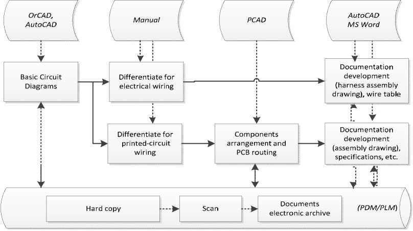
Fig. 1. Block Flow Diagram of design process at the instrument plant under consideration
-
– device (unit) solid model is not kept up to date (or is not available whatsoever) on the stage of electrical harness development.
Analyzing CAD-systems available on the market with regard to 3D electrical wiring design automation, several criteria can be established for comparison purposes: electrical harnesses solid modeling potential, possibility to integrate with ECAD-systems (wire tables import) and project implementation cost per one workstation.
The comparison results are given in Table 1 below.
Based on Table 1, the most suitable system is Solidworks, having the necessary functionality and lowest realization cost . As a complement EDA-system for Solidworks was suggested system Altium Designer (AD) [1] . Facilities of circuit diagram editor and net list’s export in AD together with specialized Solidworks module « SWR -Электрика» [2] allow to achieve efficient automated solid modeling and electrical wiring system with device live 3D model (Fig. 2).
The main advantage of suggested design scheme for the organization is the fact that they have already installed (as an experimental automation solution) Altium Designer and Solidworks systems. Integrated design cycle on this base could be achieved with minimum investments, less labor input and gives the result sooner than any other system would.
Actions for Altium Designer – Solidworks system implementation:
-
1) Input data (electrical, functional diagrams) should be developed in Altium Designer. Solid models, assembly drawings etc. should be developed in Solidworks .
-
2) Basic circuit diagram should be developed in two separate sheets for electrical and printed-circuit wiring. There should be defined some criteria to differentiate circuits for electrical and printed-circuit wiring and bound zones of developer’s responsibilities.
-
3) Provide conversion of Altium Designer export data (net list) to « SWR -Электрика» format. It is necessary to develop specialized software to convert the data, circuits fragmenting, circuits attributing (wire brand, cross section, shield, twist).
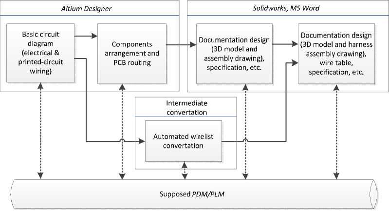
Fig. 2. Integrated design in Altium Designer – Solidworks systems
Table 1. Potential of 3D electrical wiring design automation systems
|
p fl fl -fl о |
О .3 й 3 ■3 5 Св 3 д § fl сЗ а |
s |
s |
n |
s s |
s |
s 11 |
s |
s 11 |
|||
|
$ Е а U 5 hq V о Я .Я о |
+ |
+ |
+ |
+ |
+ |
+ |
+ |
+ |
+ |
|||
|
fl р Я 00 |
H |
H |
||||||||||
|
« ао s з й и g К g -о |
+ |
+ |
+ |
fl p- |
+ |
+ |
+ |
+ |
||||
|
К 1 сЗ |
+ |
+ |
+ |
+ |
+ |
+ |
+ |
+ |
+ |
+ |
||
|
К я £ 8 fl Ф 75 fl |
+ |
+ |
+ |
+ |
+ |
+ |
+ |
+ |
+ |
|||
|
Рн 2 |
fl fl к |
a |
9 |
9 |
9 |
a |
a pf |
a |
||||
|
fl fl (Z) |
'fl и |
fl fl v 2 o |
||||||||||
|
3? |
(Z) s |
^3 |
о fl a 6 |
5 |
О £ p U |
Щ |
5 |
a |
||||
fl a
fl
fl
a
a
a
a
00 fl
a
a
a
fl 4) 00
a
a
a :
a
fl
Ф
a
a
a
00 fl
-
4) For the most efficient design automation Solidworks elements library is necessary (electrical harnesses attachments, holdings, radioelements etc.) and appointment of responsibles to fill and administrate the libraries.
Potential advantages:
-
1) Design automation of electrical wiring;
-
2) Reduction of the human factor influence (reduction of the number of mistakes associated with transfer and reconversion of data between design stages).
Potential disadvantages:
-
1) Increase of labor input at the circuit design and engineering design stages; as well as labor input required for the system implementation.
