Development of interface module emulator architecture for spacecraft life support systems

Author: Komarov V. A., Semkin P. V.
Journal: Siberian Aerospace Journal @vestnik-sibsau-en
Section: Aviation and spacecraft engineering
Article in issue: 2 vol.20, 2019.
Free access
The article gives an analysis of special characteristics of ground-based experimental evaluation of on-board radioelectronic equipment, taking the control unit of up-to date spacecraft on-board control complex as the test objective. The focus is the problem of providing testing procedures of the specific software employed in design and manufacture process. A solution of the problem is worked out on the basis of performance of a hardware-software complex which emulates interface modules for the computing module of control unit. According to the general operation algorithm of the control unit, the developed complex is regarded as a multi-user system. The main functional requirements for hardware-software emulator, regarded as the corresponding queuing system, are also defined. The results of the experiments with the computer module operation prompted the requirements for the emulator response time from the point of view of its operation stability in real strict-time mode. In order to ensure the required efficiency of operation, the emulated functions of the interface modules are classified according to the severity level of their execution determinacy. The results of experimental evaluation оf the service channel hardware design variants when applying multi-functional reconfigurable input-output digital devices allowed to develop a hardware-software emulator structural circuit based on operation parallelism of programmable integrated logic circuits and flexibility of software reconfiguration. The realization of emulated functions of selected classes within the available architecture was carried out using the corresponding hardware blocks and software module. The presented analysis of the emulator response limits was performed with the application of National Instruments technologies. The results of the developed hardwaresoftware emulator evaluation and practical application, as well as other possible ways of applying the proposed approach for tests of spacecraft on-board radio-electronic equipment and space system components were also analyzed.
Practical evaluation, spacecraft electronic equipment, multi-user system, software- hardware modeling.
Short address: https://sciup.org/148321682
IDR: 148321682 | UDC: 519.876.5: 629.783 | DOI: 10.31772/2587-6066-2019-20-2-228-235
Text of the scientific article Development of interface module emulator architecture for spacecraft life support systems
Introduction . Hardware-software complex for life support systems control of up-to date long-life spacecraft (SC) are subject to strict requirements concerning their trouble-free operation under destabilizing effects of the open space. One of the units of spacecraft (SC) on-board control complex designed at JSC “Academician M. F. Reshetnev “Information Satellite Systems” features a control unit (CU) comprising a processor module (PM) with a set of interface modules (IM) controlling the corresponding SC systems, components and/or assemblies (reaction-control system, thermal control system, electrical power system, pyro control units, actuators, etc.).
Problem description. Сomplexity of the PM software operation algorithm and several operating mode options (regular mode, on-board attitude control, etc.) required development of a specialized test complex applicable for ground testing and evaluation [1]. As a rule, the CU PM is a unified module, and the interface modules are made with regard for specific configuration of the corresponding SC service systems; that accounts for significant divergence of the software versions. Data exchange of the SC onboard central computer complex and CU PM is possible, for example, via a multiplex exchange channel, and the exchange of PM and IM is supported by a special internal data exchange interface (IDEI) [1; 2]. This exchange attachment operates special microcircuits or IP-cores, installed in field-programmable gate arrays (FPGA) of IM and performing the functions of the corresponding internal data exchange interface controllers (IDEIC). Fig. 1 presents general block diagram of the control unit.
The PM software testing procedure provides for the possibility of issuing external commands for the PM and the need to ensure two-way data communication of the PM and the corresponding IMs (fig. 1). This dictates the need for ready-made IM units connected to PM, usually featuring many hardware design and operation algorithm variants aimed for different SC. Meeting these requirements in PM software evaluation at the design stage is sometimes impossible, and cost-ineffective anyway, as it induces high expenses for supplying additional IMs [1].
Problem solving description. The problem of providing PM software advanced testing without IM can be solved by applying a special hardware-software complex emulating their performance within the CU. Here are the requirements for the emulator under development.
When the control unit installed in the spacecraft onboard control complex operates at time intervals and in sequence determined by the online leg of PM software algorithm, and by external command sources (OCCC, test instrument system, etc.), processor module of the control unit supports data exchange with corresponding interface modules through internal data exchange interface. Data exchange is performed by calling the corresponding software modules which in their turn call the IMs. Normally, calling each IM involves data recording in control registers – control data words , followed by reading the content of IM status register – status data words , displaying the issued control inputs execution and current SC systems and components status. Analysis of the state data words is followed by the execution of the corresponding leg of PM software algorithm. Let the control data words generated by the PM software be denoted by the set:
K DW = { KV = 1, I } , (1)
where I – the number of IM installed in CU; K i – control data words subset, generated by the respective software module for i IM.
IM-generated status data words are presented in the form of the set:
Z DW = { Zt\i = 1, I } , (2)
where Z i – status data words subset, generated by i IM.
Thus, conversion of IM control data words subset K i into status data words subset Z i can be generally expressed as follows:
Z = ft ( K i ) , (3)
where f i – ratio function, generally describing the corresponding conversion ( f : K i ^ Z i ). The type of f function and the form of its presentation is determined by the functional purpose, hardware design and logic of the corresponding IM.
The collection of ratio functions f i forms the set:
F. = { Й = 1, I } , (4)
where F DW – set of control data words conversions, realized by the corresponding interface modules installed in the control unit.
In accordance with the introduced designations (expressions (1)–(4)), the developed interface module emulator must ensure the realization of F DW conversion functions set for control data words set K DW generated by the corresponding software modules of the PM software and entering through the internal data exchange interface at random times (fig. 1). In this case, according to the PM software general logic, new control data words are not transferred to the corresponding IM until the status data words generated on the results of the execution of the previous ones are read, or their generation waiting time is not exceeded [2].
In view of the above, the developed IM hardwaresoftware emulator can be regarded as a multi-user system operating in an interactive dialogue mode [3–5]. In this system:
– user terminals (sources of requests) are PM software modules that generate and exchange data with the corresponding interface modules;
– requests are control data words recorded in the corresponding registers;
– request processing means performing the conversion of control data words into status data words;
– response means status data words generated in the corresponding registers.
General block diagram of the developed interface module emulator as a corresponding closed queuing system is shown in fig. 2 [3; 4].
The main objectives of the queuing system design the article deals with (fig. 2) is the development of its structure and analysis of the main approaches to realization of a service channel aimed at ensuring the required response time tr . The emulator response time tr is the sum of the in-coming control data words queuing time (KDW set) – tq and the generation time of status data words (ZDW set) – ts in correlation with conversion functions set FDW (fig. 2).
The results of experiments with operation of the control unit processor module carried out on the basis of the ground-based debugging complex of onboard electronic equipment [1] helped to determine the following characteristic features of the queuing system shown in fig. 2.
-
1. The presence of several types of control data words K i (see expression (1)), generated by the corresponding software modules, and the related time constraints imposed on the generation efficiency of the state data words Z i.
-
2. Large-scale change of the time intervals between retransmitted calls to IM (for example, from 10 us to 200 ms), the probable values of which depend on: the online leg of the PM software algorithm; hardware design and current configuration of the corresponding IM; the current status of SC systems, components, assemblies; CU operation mode [1; 2].
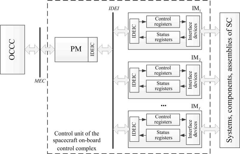
Fig. 1. General block diagram of the control unit of the on-board control complex:
PM – processor module; IDEI – internal data exchange interface; IDEIC – internal data exchange interface controller ; I – number of control unit interface modules; OCCC – onboard central computer complex; MEC – multiplex exchange channel
Рис. 1. Обобщенная структурная схема блока управления бортового комплекса управления: ВМ – вычислительный модуль; ВПИ – внутриприборный интерфейс обмена данными; КВПИ – контроллер внутриприборного интерфейса обмена; I – число интерфейсных модулей сопряжения блока управления; БЦВК – бортовой центральный вычислительный комплекс; МКО – мультиплексный канал обмена
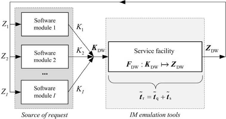
Fig. 2. General block diagram of the interface module emulator as a queuing system
Рис. 2. Обобщенная структурная схема эмулятора интерфейсных модулей сопряжения как системы массового обслуживания
The analysis of the initial data for IM design, and also for PM software design, helped to determine the following integrated classes of control data words K DW :
– Class № 1 . The time required by the emulator for generating status data words in the corresponding regis-
К1
ters is not more than 12 us ( t r ≤ 12 us );
– Class № 2 . The time required by the emulator for generating status data words in the corresponding registers exceeds 12 us, but is not more than 150 ms
К2
(12 us < t r < 150 ms).
Thus, in accordance with the determined special characteristics, hardware-software emulator of interface modules as a closed queuing system must ensure the in-coming request processing determinacy specified by К1 К2
t r and t r values, i. e. realization of real strict-time mode related to PM internal processes in the situation of incomplete empirical data on the incoming traffic parameters [6].
Preliminary evaluation of the service channel based on the programmable integrated logic circuit of the reconfigurable digital input-output device in the form of functional hardware registers linked to the IP- core of the internal interface controller revealed its low processing speed of class No.1 control data words. The corresponding time the control computer requires for reading K DW , program conversion F DW : K DW ^ Z DW , and recording
Z DW values into respective FPGA registers, designed with account for breaks formed with entry of new K DW values, made 10-15 ms (i. e. ts= 10-15 ms) regardless of control data words queuing time.
To ensure the required performance efficiency, a combined emulator architecture based on the features of FPGA operational parallelism and program reconfiguration flexibility was worked out [2; 7]. With the account for the revealed discontinuity of control data words generated by PM and the given classification of speed re- quirements for status data words generation, KDW and ZDW sets can be presented as follows:
К1 К2 К1 К2
K DW = K DW U K DW , Z DW = Z DW U Z DW , where K D К W 1 and K D К W 2 – IM-emulated control data words sets, belonging to the selected classes № 1 and № 2; Z D К W 1 and Z D К W 2 – IM-emulated status data words sets, belonging to the selected classes №1 and №2. Respectively:
II
К1 К1 К1К1
K DW = U Ki , ZDW = U Zi i=1
II
К2 К2 К2К2
K DW = U Ki , ZDW = U Zi i=1
where Ki К1 , Ki К2 and Zi К1 , Zi К2 – control data words subsets and generated on their basis state data words subsets, belonging to the selected classes № 1 and № 2 for each i IM. At that K , K1 , K , K2 g K i ; Z , K1 , Z , K2 c Z i (see expressions (1), (2)).
In a similar way, functional separation of conversion functions set F DW of the selected classes of the processed control data words is performed:
К1 К2
F DW = F DW U F DW ,
I
F dKW = U f i К1 , f i K1 c f i , i = 1
I
F dKW = U f i K2, f i К2 g f . (5)
i = 1
The developed block diagram of the interface modules hardware-software emulator, taking into account the experimentally revealed discontinuity of the processed control data words, is shown in fig. 3; it comprises a multifunctional unit for reconfigurable digital input-output from FPGA, controlled by the respective industrial computer [8].
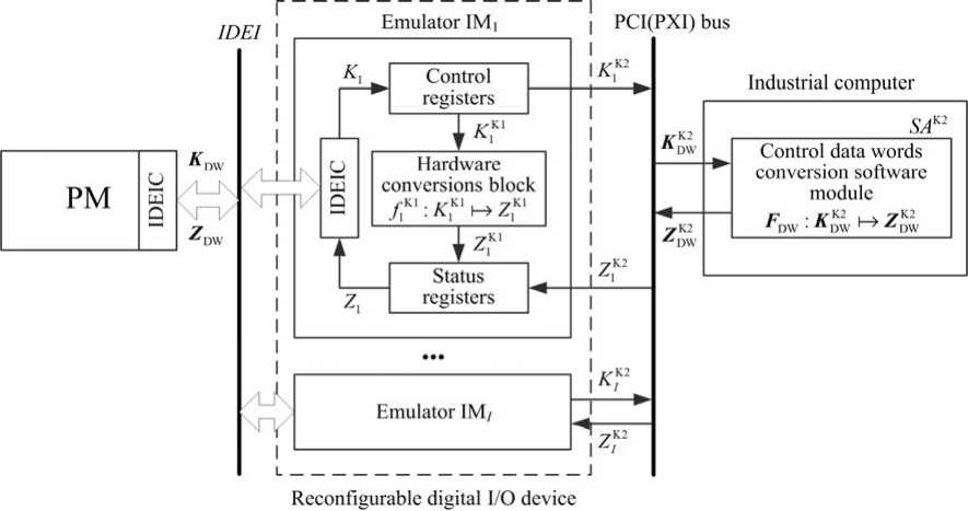
Fig. 3. General block diagram of the interface modules hardware-software emulator of SC life support system
Рис. 3. Обобщенная структурная схема аппаратно-программного эмулятора интерфейсных модулей сопряжения систем жизнеобеспечения космического аппарата
General representation of the developed hardwaresoftware interface modules emulator as queuing systems used in processing the corresponding requests (control data words) of № 1 and 2 classes is shown in fig. 4 and 5 respectively [3; 4].
In accordance with the chosen approach, individual service channels realizing ratio functions fi К1 for class No. 1 control data words (see expression (5)) come in the form of hardware conversion units making use of FPGA resources (see fig. 3). This approach ensures determinacy of Zi К1 generation delays and possibility of setting up parallel individual service channels for several emulated interface modules within a single FPGA of the applied reconfigurable digital input-output device.
Ratio functions conversions specified by the F D К W 2 set (see expression (5)) are realized by the application of the top-level program module SA К2, installed in an industrial computer (see fig. 3). When new Ki К2 values enter the control registers, a single interrupt queue is formed for all emulated IMs; in the order of their generation, interrupts are processed in the general software module SA К2 by way of reading Ki К2 , their conversion and recording Zi К2 in the corresponding hardware registers of FPGA linked with SWUI IP-cores.
The analysis of the probabilistic and temporal characteristics of queuing systems presented in fig.4 and 5 can be performed on the basis of standard approaches [3–5; 9; 10]. Taking into account the necessity of ensuring the developed emulator performance in real strict-time mode К1 К2
( tr ≤ 12 us, 12 us < tr < 150 ms) we analyze the worst situation of delays in status data words ZDКW1 and ZDКW2 generation through the example of the developed emulator approbation in IROBO-4000 industrial computer and PCI-7813R device [2; 8].
Class № 1 requests service (performing f DW : K DW ^ Z DW conversion) is carried out by means of already developed parallel service devices, the number of which equals the IM number (see fig. 4).
Here the service device is thought of as SWUI IP -core with the corresponding hardware conversion unit making use of FPGA resources. The number of service devices for K D К W 1 equals the number of IMs in the control unit; that excepts the accumulation of entering requests in the queue; thus, the emulator response time is determined by their service time. For the queuing system presented in fig. 4, the service time of requests is determined only by the time of the corresponding data words generation in status registers, and for the given hardware-software emulator implementation variant based on the results of the corresponding FPGA project development the time equals 2 clock-cycles [11–13]:
^ = ^ = 2. X = 2. 1 = 50 .io-9s, fcs 40 -106
cs where fcs – operational clock speed of FPGA project.
When new control data word values KiК2 of No. 2 request class enter the corresponding hardware registers, a unified queue of hardware interrupts is formed for all emulated IMs. The interrupts data are processed in the SAК2 software module in the order of their generation (conversion FDW : KDW ^ ZDW). Maximum delay of state data words ZiК2 generation when I = 8, caused by control data words KiК2 accumulation due to queuing in interrupt processing (see fig. 5) may be determined on account of the above evaluation results of the service channel implementation; the resulting expression is [3–5]:
К2 К2 К2
max 1 1 r ) = max 1 1 q ) + max 1 1 s ) =
( -К2 К2
t s ) + max ( t s ) = 8 - 15 - 10 3 = 120 - 10 3 s.
Thus, the maximum values of response time in status data words generation for K D К W 1 and K D К W 2 obtained in use of the specified hardware-software IM emulator architecture meet the requirements formulated according to the experimental evaluation of PM CU performance. The suggested emulator architecture allows for modification of the implemented in SA К2 program module ratio sets F D К W 2 avoiding the FPGA project recompilation, thus providing its flexibility and unification for further industrial application.
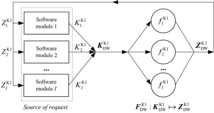
Fig. 4. Representation of the hardware-software interface modules emulator as a queuing system for processing of class No. 1 control data words
Рис. 4. Представление аппаратно-программного эмулятора интерфейсных модулей сопряжения в виде системы массового обслуживания при обработке слов данных управления класса № 1
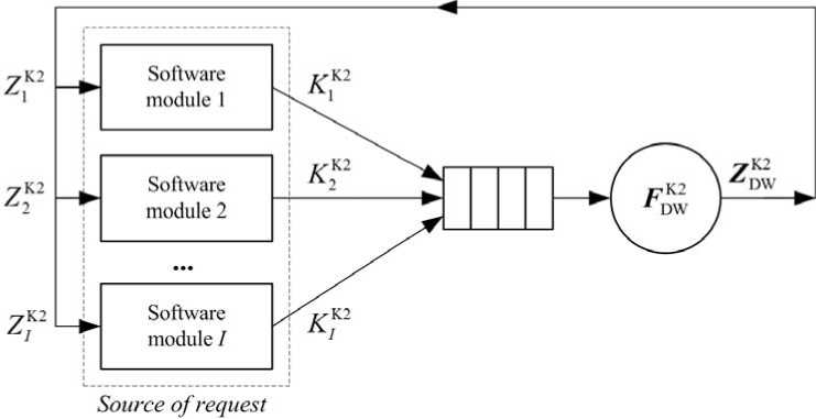
Fig. 5. Representation of the hardware-software interface modules emulator as a queuing system for processing of class No. 2 control data words
Рис. 5. Представление аппаратно-программного эмулятора интерфейсных модулей сопряжения в виде системы массового обслуживания при обработке слов данных управления класса № 2
Conclusion. The proposed know-how (fig. 3) has been evaluated and successfully put into operation at the department of astrionics design and test operations of spacecraft control systems in SC “Academician M. F. Reshetnev “Information Satellite Systems” within the ground-based debugging complex of onboard electronic equipment [1; 2; 14; 15]. The debugging complex facilities emulating control unit interface modules of the SC onboard control complex with application of the proposed approach feature a set of unified devices (hardware modules) and the corresponding “FPGA firmware” (developed IMs) that can be independently modified and then compiled in arbitrary order within the corresponding device [11–13].
Application of the PCI-7813R reconfigurable digital input-output board allowed emulation of eight interface modules of the control unit; that reduced the cost of PM software evaluation by several times and shortened its testing time. Further operation of the developed hardwaresoftware emulator proved that the used approaches and developed techniques were correct and efficient [11–15]. The developed hardware-software emulator provides for practical evaluation of regular PM software in the environment simulating real operating conditions of SC; that was achieved by applying certain methods simulating inflight contingency situations for onboard radioelectronic equipment and spacecraft: a number of faults, such as internal interface exchange errors, one of the IMs partial malfunction or failure, SC unit/component/ assembly malfunction, etc. [14; 15].
In general, the evaluated approaches to the method of software and hardware modeling with FPGA application can also be valid for analysis of space systems operation when using special units (components) of ground-based and / or onboard electronic equipment for simulating the changing conditions of transmitting signals via communication channels that depend on the propagation medium, payload characteristics, SC path, etc. [16–18].
References Development of interface module emulator architecture for spacecraft life support systems
- Pichkalev A. V. [The terrestrial debugging complex for onboard radio-electronoc equpment]. Reshetnevskiye chteniya : materialy XIV Mezhdunar. nauch. konf. [“Reshetnev readings”. Proceed. of XIV Intern. scientific. conf]. Krasnoyarsk, 2010, P. 515–516 (In Russ.).
- Komarov V. A., Pichkalev A. V. [Application of NI FPGA technologies in testing spacecraft onboard equipment]. Intellekt i nauka: trudy XI Mezhdunar. nauchn.-prakt. konf. ZHeleznogorsk, 28–29 aprelya 2011 g [Intellect and science. Proceed. of the XI Intern. scientific-practical. conf., Zheleznogorsk, April 28–29, 2011]. Krasnoyarsk, 2011, P. 146–148 (In Russ.).
- Takagi H. Queueing analysis. A foundation of performance evaluation. Finite Systems. 1993, Vol. II, 560 p.
- Allen A. O. Probability, Statistics, and Queueing Theory with Computer Science Applications, 2nd ed. Academic Press, New York. 1990, 740 p.
- Komarov V. A., Sarafanov A. V. [Development of a mathematical model of a multi-user mode of hardware and software systems operation remote access]. Informatsionnyye tekhnologii. 2009, No. 3, P. 67–74 (In Russ.).
- Burdonov I. B. Kosachev A. S., Ponomarenko V. N. [Real Time Operating Systems]. Preprinty Instituta sistemnogo programmirovaniya RAN. Preprint 14, Moscow, 2006, 98 p.
- Baran E. D. LabVIEW FPGA. Rekonfiguriruyemyye izmeritel’nyye i upravlyayushchiye sistemy [Lab-VIEW FPGA. Reconfigurable measurement and control systems]. Moscow, DMK Press Publ., 2009, 448 p.
- Ofitsial’nyy sayt kompanii National Instruments [Official website of National Instruments] (In Russ.). Available at: http://www.ni.com /ru-ru.html (accessed 16.11.2018).
- Averill M. Law, David M. Kelton. Simulation modeling and analysis, 4th edition. McGraw-Hill, 2007, 768 p.
- Komarov V. A., Sarafanov A. V. Simulation of the operation of multiuser distributed measurement and control systems. Measurement Techniques. 2011, Vol. 54, No. 2, P. 129–134. Doi: 10.1007/s11018-011-9695-y.
- Komarov V. A., Yudin V. A., Poleshchuk V. V. Emulyator interfeysnykh moduley sopryazheniya ispolnitel’nykh ustroystv sistem zhizneobespecheniya KA [Emulator of interface modules of executive devices of SC life support systems ]. Patent RF, No. 2013612869, 2013.
- Komarov V. A., Yudin V. A., Kazaykin D. S. Emulyator interfeysnykh moduley sopryazheniya kontrol’noizmeritel’noy sistemy [Emulator of interface modules of instrumentation and control system]. Patent RF, No 2013612871, 2013.
- Komarov V. A., Yudin V. A. Emulyator interfeysnykh moduley sopryazheniya s analogovymi signalami [Emulator of analog signal interface module]. Patent RF, No 2013612874, 2013.
- Nedorezov D. A., Pichkalev A. V., Krasnenko S. S., Nepomnuash О. V. [Application of FPGA for modeling of operation logic of spacecraft onboard radioelectronic equipment]. Vestnik SibGAU. 2014, No. 1 (53), P. 133–136 (In Russ.).
- Nedorezov D. A., Legalov A. I., Nepomnyashchiy O. V., Krasnenko S. S., Ankudinov A. V. [Methodology of mutational testing for ground tests of spacecraft onboard equipment]. Sistemy i sredstva informatiki. 2014, Vol. 24, No. 1, P. 73–79 (In Russ.).
- Leitner J. Space technology transition using hardware in the loop simulation. Aerospace Applications Conference, 1996. Proceedings. 1996. IEEE. Vol. 2, P. 303–311.
- Pu Di, Wyglinski A. M. Digital Communication systems engineering with software-defined radio. Artech House, Boston. 2013, 288 p.
- Komarov V. A., Pazderin S. O., Matveyenko S. P. Imitator poleznoy nagruzki kosmicheskogo apparata [Spacecraft Payload Simulator]. Patent RF, No. 181746, 2018.
