Development of mechanical test procedure for the fuel bellows tanks

Author: Ermoshkin Yu. M., Orlov S.A., Usanov A. Yu.
Journal: Сибирский аэрокосмический журнал @vestnik-sibsau
Section: Авиационная и ракетно-космическая техника
Article in issue: 5 (26), 2009.
Free access
The mechanical qualification and acceptance test requirements are considered for the fuel bellows tanks. Some procedural mistakes taking place during these tests are described.
Spacecraft, tank, storage and feed unit, mechanical tests, resonance
Short address: https://sciup.org/148176106
IDR: 148176106
Text of the scientific article Development of mechanical test procedure for the fuel bellows tanks
For decades the fuel storage/feed units based on the bellows tanks are successfully used in the monopropellant propulsions of the domestic spacecrafts (SCs). In order to use the fuel storage units for new generation SCs (i. e. to be exposed higher mechanical loads) there was a necessity to perform supplemental mechanical tests to prove their durability.
SC hardware ground test plan includes the acceleration, vibration and shock tests [1; 2]. The tests levels are based on the data obtained from hardware operating conditions analysis, equipment mass and its allocation on the SC.
The storage and feed unit (SFU) manufacturer has to procure off-the shelf tanks from other supplier and then has to equip it with supplemental hardware in order to obtain the SFU as an item of SC propulsion.
During the SFU development testing, bellows of two tanks were corrupted (along an external crimp weld) when they were exposed to mechanical environment. This damage occurred directly along the weld, and not in an area around the weld; it was typically if the weld was well done i. e. this damage designated an insufficient quality of the join. It is necessary to note that such welds in the tanks are critical because they influence the strength of the whole assembly; the thickness of weldment isn’t great, while the total length of weld may be hundreds of meters long. However, all the delivered tanks for the integration of the SFUs have passed the acceptance tests at the manufacturer’s site.
In order to analyze the failures of tank bellows and to generate the levels of durability and acceptance tests, supplemental mechanical tests of two SFUs had been conducted. This work is meant to review all the test results and to identify the possible procedural mistakes that have made it impossible to detect manufacturing flaws during the acceptance tests of tanks.
Test Objectives. During the test campaign it was necessary to achieve a set of mutually complementary objectives:
-
– to detect the rupture sources of tank bellows;
-
– to develop a technique for determination of low eigenfrequencies of the bellows located inside a tank;
-
– to estimate an influence of test procedure on the test data;
-
– to confirm or exclude an influence of the test hardware (fixture, tools, control system, etc) to the test results;
-
– to update the durability/acceptance test levels for tank and SFU.
Test equipment and mechanical loads. The following mechanical tests were performed:
-
– resonance search within a frequency range of 5 Hz to 2,000 Hz with level of 0,5 g and a scanning rate of 2 octave/min;
-
– sine vibration within a frequency range of 5 Hz to 2,000 Hz with levels of 1 to 12g;
-
– random vibration within a frequency range of 20 Hz to 2,000 Hz with levels of 0.02 to 0.2 g2/Hz;
-
– quasi-static loads with levels of ±10 g;
-
– shocks with levels of ±40 g.
The test specifications were generated proceeding from the SFU operation conditions at levels of the SC and in compliance with an approach as described in [3; 4]. They have met the requirements as established in [1; 2]. The tests were conducted in few phases changing the levels and duration of loading. The following equipment was used:
-
– centrifuge C-400;
-
– shock test bench ST-800;
-
– vibration shaker LDS V894/440.
Beforehand, the test equipment and test fixture were subjected to approval. The equipment’s low eigenfrequency is about 1,000 Hz. All the test hardware corresponded to the test standards according to the test specification accuracy and provided the mechanical loading of the SFU and was measured with the following tolerances:
-
– vibration acceleration amplitude: ±10 %;
-
– vibration acceleration power spectral density: ±6 dB;
-
– vibration frequency: ±2 % within a frequency range of 5Hzto2,000Hz;
-
– vibration acceleration RMS value: ±4%;
-
– shock acceleration: ±15 %;
-
– linear acceleration: ±10 %.
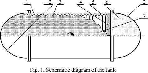
Description of Tank Design. For the following analysis and identification of the bellows failures let us consider a design of the bellows tank. Figure 1 depicts its schematic diagram. The tank consists of a cylindrical case 1 with spherical bottoms 2 . The bellows 3 isweldedontheaftof a cylinder 1 . Afluoroplasticring 4 isinstalledonafreeendof the bellows to provide gliding for the bellows on the case 1 along an axis and to restrain sideward shift. Minimum clearance 5 exists between the case and bellows. A gas cavity 6 is formed in the spherical bottom at a side of fluoroplastic ring 4 . Bellows are filled with a simulator of fuel (water).
Estimation of SFU eigenfrequencies. After the first phases of testing it became clear that the shock and quasistatic (linear) loads can not be a source of SFU failures, not speaking about the damage of tanks through loads without loss of bellows tightness.
These results are in compliance with the calculated stresses in the elements of tanks and they show that maximal stresses in bellows at the specified loads should be from 8 to 10 times less than the ones allowed. Before testing we also evaluated the low eigenfrequencies for the bellows and tank. The value of low eigenfrequency for the bellows is 8 Hz. Numerical analyses of stresses and eigenfrequencies were performed in accordance with reference [5].
The evaluation of low frequency for the tank case asin [6] gave a value of about 300 Hz. Eigenfrequencies for the SFU reinforcement (the control points are the following: 1 , 2 , 4 , 7 ) are within a range of 150 to 500 Hz (these results were obtained during earlier tests of the SFU). Thus the test fixture, whose eigenfrequencies are above 1,000 Hz, could not impact on strength of low-frequency bellows as well as on the tank and SFU reinforcement responses. This is why the main attention was paid to the analysis of SFU vibration loading and test procedures.
Vibration test procedures and plans. Figure 2 depicts the locations of accelerometers in the tank case for recording the accelerations during the vibration test (the non-labeled points stand for recording the accelerations along three directions). The objective of the first testing phase was to determine the low eigenfrequencies of bellows.
Since it was impossible to measure the frequency of the fueled bellows inside the air-tight tank under pressure directly, the experimental data about the eigenfrequency of bellows was gained by a method of indirect measurements.
To justify a possibility of performing such measurements agroovewasmadeononeofaSFUspecimencaseinthe field of sensor 5Y and an accelerometer was installed on a plane of sensors 5 allocation.
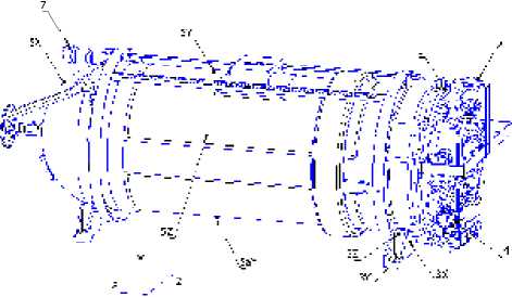
Fig. 2. Diagram of accelerometers allocation on the SFU
During the vibration test of this SFU by the wobbulator method [4] (the scan rate was 0,6 octave/min and level of load was 0.5 g), the accelerometer installed on the bellows and the accelerometers 5Y , 5Ya , 5Z showed a presence of same frequency resonances. So using the indications of the accelerometers 5Y , 5Ya and 5Z we can be judge about the eigenfrequencies of the SFU bellows. This effect can be explained easily: the gap between the bellows and the tank is small (~1 mm), when resonance phenomena arise, the bellows collide with the tank case at a resonant frequency, which is recorded by the accelerometers installed on the tank case.
The next testing phase was done to determine the lowest eigenfrequency of the fuelled bellows at levels of the SFU. The testing was conducted with the different scan rates of frequency (2 octave/min and 0.5 to 0.6 octave/min).
Test results. Resonant frequency search tests for the SFU with the fuelled tank conducted at the frequency scan rate of 2 octave/min have shown that no resonant frequencies exceed 17 Hz (ref. fig. 3). Thus, according to the conventional test procedures as described, for example in [7] a vibration test can be conducted starting from 10 Hz. Such approaches have been carried out at the tank manufacturer’s site during the selective and acceptance tests’ performance.
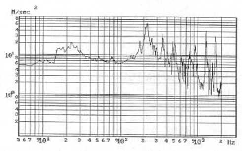
Fig. 3. Acceleration plot at point 5Ya during resonance search test with scan rate of 2 octave/min
However, as it is shown in figure 4, when decreasing a scan rate down to 0.5...0.6 octave/min within a frequency range of 7 to 8 Hz, a resonance appears (i.e. increasing a vibrational amplitude by 2 to 4 times), which is absent in figure 3.
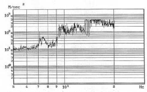
Fig. 4. Acceleration plot at point 5Ya during resonance search test with scan rate of 0.6 octave/min
This phenomenon can be explained the following way: the bellows contain a bulk of fluid, which makes it fairly inertial. At a scan rate of 2 octave/min the resonances don’t have time to develop which is mistaken as the absence of any resonant frequency. However, when decreasing a scan rate to 0.6 octave/min the bulk of fluid inside the tank is capable to develop the oscillations of both bellows and fluid in a low frequency range (i. e. resonance).
It should be noted that the vibration tests at the tank manufacturer factory were envisaged in accordance with a step acceleration method for every frequency sub-range from 10to2,000Hz.
Then the vibration tests at the SFU manufacturer factory were conducted in accordance with the methodology providing smooth change of frequency from the lower boundary of 5 HZ to the upper of 2,000 Hz with a smooth change of acceleration from 1 g to 12 g (wobbulator method). Also the wideband random vibration tests equivalent to the sine vibration with a power spectrum density level of up to 0.2 g2/Hz were conducted.
Analysis of differences in the SFU and tank test procedures. The differences detected in the test procedures for the tank and SFU have required performing an additional analysis. Conducting the tests from a frequency of 10 Hz eliminated loading of the bellows with maximal strains within a range of resonant frequencies from 7 to 8 Hz, because the amplitude of displacement was inerasable to a square of frequency [7]. In addition, after passing an octave frequency range with step increasing of load, the shaker was switched off and it carried out a new load level setting up by the test control system. It had an attenuation effect on the occurring oscillations; when passing the next frequency range the significant expenditure of energy was required to cause the oscillations of bellows with fluid again.
A validity of this statement is confirmed by the response plot of point 5Ya obtained from the results of SFU random vibration tests and depicted in figures 5 and 6. The lower boundary of frequency range was 20 Hz and the structural response was at noise level when performing the test with thePSDupto0.05to0.07 g2/Hz (fig. 5), within a range of up to 20 Hz. When increasing the PSD to 0.2 g2/Hz (ref. fig. 6), the power injected into the bellows was sufficient to increase the low frequency oscillations even within a frequency range which was excluded from test specification (below 20 Hz).
So it became comprehensible that the rupture of bellows might be caused directly by environment vibration within a low frequency range of up to 10 Hz, which impacts on the low quality bellows weld areas.
As vibration within a range of frequency ranges to 10 Hz, which is not used for qualification, acceptance and selective tests of the tank at the manufacturing factory, the weld defects are not detected.
Test based on the wobbulator method (where a low boundary of frequency is 5 Hz) applicable at the SFU manufacturing factory have calculated the tougher loading of the bellows; compared with tests based on the method where stepwise acceleration is applied within the sub-ranges of frequency. So the hidden weld defects are detected the SFU test phase only.
We shall note that the method based on stepwise acceleration had been used during he 1960s and 1970s. Today this method is not recommended to use because the digital control systems are exploited in compliance with ESA and NASA standards [1; 2].
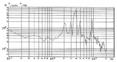
Fig. 5. Acceleration plot at point 5Ya during a wideband random vibration test with PSD of up 0.07 g2/Hz
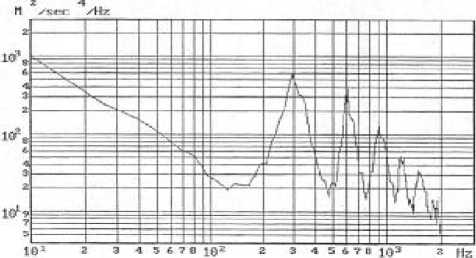
Fig. 6. Acceleration plot at point 5Ya during a wideband random vibration test with PSD of up 0.2 g2/Hz
The qualitatively higher vibration test procedures allow the detecting of bellow weld defects. It is necessary to note that no any requirements of existing test specification are formally disturbed at the tank production factory, but the applied acceptance/selective test procedure don’t allow the detection of bellow weld defects.
At the same time, analysis shows that in ranges of intermediate and high frequencies a wideband random vibration environment is the closest (of physical nature) to actual mechanical environment as a response of SC structure to acoustic loads during the launch phase for the SFU at level of SC [1; 2; 7; 8]. Wideband random vibration allows the loading of the SFU within a wide amplitude/frequency range without the damage of high quality fabricated equipment (fig. 6).
From the said above, we can make the following conclusions and recommendations.
The most probable cause of the tank’s bellows destruction during the SFU mechanical tests was the low quality of bellows crimp welds which have not been detected at the tank production factory, combined with overloads at resonant frequency within a low frequency range (5 to 8 HZ).
During the acceptance/selective tests of the tank at the factory for the purpose of detecting hidden bellows weld defects, it is advisable to use the sine vibration test in low frequency range of 5 to 100Hz(notlessthen5to20Hz) based on a wobbulator method with scan rate no higher than 0.5 to 0.6 octave/min.
It is advisable to use a wideband random vibration test with PSD of 0.05 to 0.07 g2/Hz at the SFU factory during acceptance tests; and it is better to use a sine vibration test within a low frequency range and wideband random vibration testwithPSDofupto0.2 g2/Hz for the qualification tests.
