Development of procedures for determining the optimal placement of symmetration devices for electrical supply systems 0.4 kV with motor-actuated load

Author: Romanova Viktoria V., Khromov Sergey V., Suvorov Ivan F.
Journal: Журнал Сибирского федерального университета. Серия: Техника и технологии @technologies-sfu
Article in issue: 5 т.11, 2018.
Free access
In this paper, we consider the development of methods for determining the optimal location of symmetrization devices for 0.4 kV power supply systems with motor-actuated load. The methodology includes the features of electric consumers and their geographical location. The practice procedures for application of the existing power supply system the Taptugary village, the Mogochinsk region, the Trans-Baikal Territory was given as an example. The practical significance for the developed application procedures was justified. The optimal solution of balancing problem based on economical parameters was obtained.
Power supply system, voltage asymmetry, asynchronous motor, power losses
Short address: https://sciup.org/146279533
IDR: 146279533 | UDC: 621.311 | DOI: 10.17516/1999-494X-0051
Разработка методики определения оптимального размещения устройств симметрирования для систем электроснабжения 0,4 кВ с электродвигательной нагрузкой
Рассматриваются вопросы разработки методики определения оптимального размещения устройств симметрирования для систем электроснабжения 0,4 кВ с электродвигательной нагрузкой. В методику заложены особенности электропотребителей и их географическое расположение. Приведен пример применения методики для существующей системы электроснабжения с. Таптугары Могочинского района Забайкальского края. Дано обоснование практической значимости применения разработанной методики. Получено оптимальное решение вопроса симметрирования исходя из экономических показателей.
Text of the scientific article Development of procedures for determining the optimal placement of symmetration devices for electrical supply systems 0.4 kV with motor-actuated load
This work scope is development and approbation for determining the optimal location of symmetrization devices for 0.4 kV power supply systems with motor-actuated load (using the example of the Trans-Baikal Territory).
Task setting
In accordance with the set goal the task on development of the power supply system calculation algorithm subject to using the balancing devices and their installation locations was implemented, based on which the procedure will be built. The diagram for calculation algorithm of the power supply system subject to using the balancing devices and their installation locations is given in Fig. 1.
Based on the experimental research data of the basic PQI, the information on the value of power loss in the elements of the power supply system under study, and, in addition, relying upon customers' allowable operating modes, it is possible to select the parameters of the balancing devices and determine the optimal location of these devices in the power supply system. Thus, the calculation of the value for supplementary power losses due to voltage asymmetry will enable to define the economic feasibility for carrying out particular actions for asymmetry removal, and besides, to specify the optimal application and location of these devices.
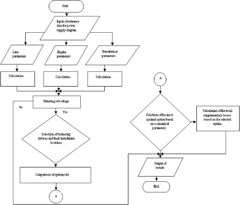
Fig. 1. Block diagram for calculation algorithm of the power supply system subject to using the balancing devices and their installation locations
Research results and their discussion
The developed procedure is a matter of interest during development of projects for power supply systems for regions with available non-linear loads.
The main criterion for the procedure application consists in excess of the voltage asymmetry coefficient statistical value ( K ) in negative-phase sequence for this PSS over the allowable value K for AM (Table 1) installed in the same power supply system. The required k 2U value is selected based on the customer's allowable operating mode. The values of the allowable value K2U for AM are taken from the research results [3].
The procedure can be implemented in the following sequence:
-
1) let us determine the losses for symmetrical operating modes in the main elements of the power supply system.
Calculation of supplementary power losses is made by formulas given in [4].
The losses in the power transmission lines are determined based on the expression:
where I 1 – symmetrical operating mode current (positive-phase sequence current); r ph – phase conductor resistance.
Real-power Δ P ⸍ and reactive Δ Q ⸍ power losses for double-wound transformers are determined based on the expression:
ДР = дтИ 2, (2)
ДО ' = ^^ , (3)
100-n Srt where Pk, Uk, Srt – nameplate data of individual transformer; S – substation full load (total of individual transformer loads); n – number of one-type transformers in the substation, parallel operating.
-
2) let us determine the losses for asymmetrical operating modes in the main elements of the power supply system.
The available amplitude and angular asymmetry during estimation of increase of supplementary losses as compared to symmetrical operating mode can be accounted using the coefficient K as:
K^^l+Kb + KSr^l + ^^i^), (4)
where K 2 I , K 0 I – coefficients for asymmetry of negative-phase and zero-phase sequence currents. Based on the results of processing the statistical data for basic PQI in 0.4 kV network nodes of the Mogochinsk region, the Trans-Baikal Territory, we take on the values equal to K 2 I = 5%, K 0 I = 4.6%, K 2 U = 4.95%; R N, R PH – resistances of the neutral and phase conductors.
Table 1. Table of allowable values K 2U
|
Motor model |
Motor power, Р L , kW |
Allowable value K 2U , % |
|
4A132S4Y3 |
7.5 |
1.8 |
|
АI132М4 |
11 |
1.26 |
Accordingly, taking into account (3), the expression (1) will be as follows:
The supplementary losses of the real-power in the asynchronous motor are determined based on the expression:
^^ SUPLAM = 2,41клмК 2и Р £ ,
where k AM – the coefficient, accounting the particular motor parameters (rated power, stator copper losses, starting current-to-rated current ratio); K2U – coefficient of voltage asymmetry in negativephase sequence; P L – rated motor real power.
The coefficient kAM value for industrial overall load is advised to take on equal to 1.85.
During long-sustained asymmetrical operating mode, due to the flow of negative-phase sequence currents, the supplementary power losses occur in the power transformers, which can be determined by the following formula:
^ ps„,„« =^ „ k^ p„+b-;;A
\ usc / where K2U – the voltage asymmetry coefficient in negative-phase sequence; ΔPIM – losses during idle mode; ΔPSC – losses during short-circuit mode; USC – short-circuit voltage.
-
3) let us proceed to taking the special measures for removal of the voltage asymmetry and determination of the optimal application and location of these devices.
Let us calculate the optimal location and selection of the balancing devices. The following subtasks shall be solved for this purpose:
-
а) detect the motor, which is most sensitive to voltage asymmetry out of all motors present in the power supply system,
-
b) determine the losses for asymmetric operating mode in the main elements of the power supply system with installed balancing device in the central node of the diagram. Calculate the payback period for installation of the balancing device.
Calculation of the payback period for installation of the balancing device can be determined by the following formula:
рр =--------------------------------------
((kPsupl. w + AQsupl. w) - (kPsupl. + S – the total cost of the installed balancing devices; kPsupl. w + kQsupl. w - supplementary losses without the balancing devices; ^Psupl. +^Qsupl. -supplementary losses with the balancing device; С – the cost of the electric power.
-
c) determine the losses for asymmetric operating mode in the main elements of the power supply system with installed balancing device in each motor individually. Calculate the payback period for installation of the balancing device,
-
d) based on calculation results analysis select the most optimal option,
-
e) carry out installation of the balancing device in the power supply system.
To implement the procedure let us consider the power supply system section of the Taptugary village, the Mogochinsk region, the Trans-Baikal Territory.
The following reference information was used for execution of this work:
-
1) the results of processing the statistical data for basic PQI in 0.4 kV network nodes of the Mogochinsk region, the Trans-Baikal Territory,
-
2) the configuration of the power supply system section of the Taptugary village, the electric power consumers' characteristics.
The power supply system, on which the procedure was approved, is given in Fig. 2. The power supply system section diagram consists of:
-
1) line 1 – wired with АS-25 (steel-aluminium conductor), the line length is 350 metres, feeds 7 private residence houses with furnace heating,
-
2) line 2 – cabled with GRSh 3*50+1*35 (cable with flexible core, rubber cover and poly amide silk isolation), the line length is 50 metres, feeds the two-storeyed residence house, the primary school, the kindergarten, the administration building and the library,
-
3) line 3 – cabled with AVVshv 4*50 (cable with aluminium core, PVC jacket, with protective layer in the form of pressed out hose), the line length is 70 metres, feeds the boiler house with two boilers and motors: the model 4А132S4Y3 Р L =7.5 kW, 2 pcs., the smoke exhaust fan Р L =3 kW, the draught fan Р L =1.4 kW,
-
4) line 4 – wired with SIP 4*25 (self-supporting insulated conductor), the line length is 150 metres, feeds two ban mills with motors model AI132M4 Р L =11 kW, 2 pcs.
Calculation of the power supply wiring diagram was made using the widely spread computer program Microsoft Office Excel. Main calculation results are summarized in Table 3. The cost indicators are taken from the sources [5, 6].
Thus, following the calculation results we obtained the value of power losses in the main elements of the power supply system for the symmetrical operating mode, the asymmetrical operating mode without installation of the balancing device and the asymmetrical operating mode with installed balancing device. Based on the data of results let us determine the number, power and the location for installation of the balancing device.
TM 1000/10/0,4
Line 4
Fig. 2. Power supply system section diagram of the Taptugary village
Table 2. Reference data of the village Taptugary network section
|
Parameter |
Line 1 |
Line 2 |
Line 3 |
Line 4 |
TS |
|
Power, kVA |
30.4 |
49.4 |
20.9 |
25 |
100 |
|
Current, A |
80 |
130 |
55 |
65.7 |
330.7 |
Table 3. Calculation of payback period for installation of the balancing device based on supplementary power losses
|
Losses |
∆P +∆Q, kVA |
|
1) During symmetrical operating mode |
17.0+j16.0 |
|
2) Supplementary losses during asymmetrical operating mode |
|
|
without balancing device |
8.4+j0.2 |
|
during installation of the individual balancing device in the motor – option 1 |
2.5+j0.2 |
|
during installation of the common balancing device in all motors – option 2 |
2.7+j0.2 |
|
3) Cost of balancing devices, thu. rbs. |
- |
|
Balancing device РL = 9 kW |
39 |
|
Balancing device РL = 11 kW |
45 |
|
Balancing device РL = 45 kW |
126 |
|
Cost kW*hour, rbs |
5 |
|
Total cost of BD (balancing device), option 1, thu. rbs. |
168 |
|
Total cost of BD, option 2, thu. rbs. |
126 |
|
Payback period, option 1, months |
8.28 |
|
Payback period, option 2, months |
5.95 |
Analysing the data given in Table 3 the conclusion can be made that for considered diagram it is economically viable to install one balancing device with 45 kW power on the common node of the lines 3, 4, containing the motor-actuated load, but not the individual one on each motor.
Following the results of the procedure implementation we found the necessity for application of the balancing devices for industrial consumers in the diagram under research. We selected the most cost-effective location of the balancing device in PSS.
It is evident that only upon available reliable information about the levels of PQI distortion, about the operating modes of the power consumers it is possible to make up the requirements specification for PSS designing and to select the optimal parameters for the balancing devices.
Conclusion
The developed procedure is of practical interest for designing of 0.4 kV power supply systems containing the motor-actuated load under voltage asymmetry conditions. The specifics of the electric power consumers' operating modes and their geographical location are built in the procedure.
Application of the procedure in PSS with available motor-actuated load will allow increase the operating reliability and efficiency of the asynchronous motors.
The proposed procedure will be the basis for implementation of the task for creation of the software complex allowing to make quick and accurate calculation of the power losses, to determine the economical feasibility of provision special measures for removal of the voltage asymmetry, for determination of optimal application and location of the balancing devices.
The work was executed within the framework of FSBEI HPE Trans-Baikal State University Council for Research and Innovative Activities Scientific Grant No. 247 – GR of 30/01/2018 implementation.
References Development of procedures for determining the optimal placement of symmetration devices for electrical supply systems 0.4 kV with motor-actuated load
- ГОСТ 32144 -2013. Электрическая энергия. Совместимость технических средств электромагнитная. Нормы качества электрической энергии в системах электроснабжения общего назначения. М.: Стандартинформ, 2014. 19 с
- Романова В.В., Хромов С.В. Состояние качества электрической энергии в распределительных сетях Забайкальского края. Электроэнергетика байкальского региона: проблемы и перспективы: материалы Всероссийской научно-практической конференции, 2016, 20 -25
- Романова В.В., Хромов С.В., Суворов И.Ф. Новый подход к нормированию коэффициента несимметрии напряжений по обратной последовательности K2U для узлов нагрузок систем электроснабжения с асинхронными двигателями. Современные технологии. Системный анализ. Моделирование, 2017, 1 (53), 209 -214
- Дед А.В., Паршукова А.В., Халитов Н.А. Оценка дополнительных потерь мощности от несимметрии напряжений и токов в элементах систем электроснабжения. Международный журнал прикладных и фундаментальных исследований, 2015, 10, 421 -425
- Трехфазные стабилизаторы напряжения 380 вольт . Режим доступа: http://voltmarket.ru/catalog/trekhfaznye_stabilizatory
- Энерго 24. Тарифы на электроэнергию для Читы и Забайкальского края с 1 июля 2016 года . Режим доступа: https://energo-24.ru/authors/energo-24/11017. html
