Development of the CYCLOPS CubeSat payload

Author: Sotnikova N.V., Kadadova A.V., Kadochnikov D.M., Utkin V.V.
Journal: Siberian Aerospace Journal @vestnik-sibsau-en
Section: Aviation and spacecraft engineering
Article in issue: 1 vol.24, 2023.
Free access
The number of CubeSat satellites launched has been increasing over the past decades. These satellites have a number of advantages: short development time, low cost, possibility of modifications for certain scientific tasks and testing of technical solutions and new developments. This article describes payloads of a small spacecraft: CubeSat 3U CYCLOPS designed by D.F.Ustinov Baltic State Technical University "Voenmeh" within grant under Space-Pi program. The purpose of the study is to create, test and study the performance of payload modules of the vehicle, built using commercially available components, under space flight conditions. The text describes the structure of interaction between the payload and the OrbCraft-Pro 3U platform from Sputnix LLC. The process of development of payload control board is con-sidered. The control system software for mechatronic and multiaxis actuator modules with logging and error correction is described. In addition to the above-mentioned modules, the payload control system was also developed to carry out a series of experiments in the presence of a small spacecraft in orbit. The paper explains how the spacecraft communicates with the ground via special software Houston control applica-tion and Houston Telnet. The results describe tests performed on the mechanical components of the space-craft. Examples of telemetry packets received from on-board the spacecraft are given. The article also re-flects further plans for the project and the prospects of using the developed hardware for implementation in large-scale space systems and complexes. Also as part of the project students were able to gain engineering experience in the development of devices designed to work in space conditions.
Small spacecraft, payload, module, satellite, communications system, CAN, CubeSat, TELNET
Short address: https://sciup.org/148329682
IDR: 148329682 | UDC: 629.78 | DOI: 10.31772/2712-8970-2023-24-1-144-154
Text of the scientific article Development of the CYCLOPS CubeSat payload
Now, there is an active development of near-Earth space. The design and launch of small spacecraft has become available to schoolchildren and students. The list of programs and grants providing access to space technologies to future engineers of the space industry is growing. The most popular format of nanosatellites for such projects is the SS CubeSat 3U ICA. CubeSat has the size of one unit (1U) 100×100×100 mm, the sides of which are covered with solar panels, scientific equipment is located inside the device [1; 2]. The most time-consuming in terms of time and priority in the development cycle of a space product are the tests of technical solutions involved in the payload.
Payload testing in space based on CubeSat allows you to use and test the element base and technologies for more serious large-sized spacecraft [3].
About the project
At the Baltic State Technical University "VOENMEH" named after D. F. Ustinova" within the framework of the won competition "On Duty on the Planet" (turn 5) of the Space-pi project, organized by the Foundation for the Promotion of Innovation, the development of a payload for the SS CubeSat 3U format was carried out. The mission of the Space-pi project is to involve young people in solving engineering problems in the space industry [4].
Students from the Center for Scientific and Technical Creativity of our university participated in the development of a multi-stage executive module and a mechatronic module for testing engineering solutions using the OrbiCraft-Pro 3U CubeSat satellite platform from Sputnix [5]. The purpose of the project is to train students, create, test and study the operation of the payload modules of the spacecraft, built using commercially available components, in space flight conditions [6].
Description of payloads
As part of the Space-pi project, our university has created three payloads: a multi-stage executive module (EM), a mechatronic module and an energy storage module based on supercapacitors. The battery of supercapacitors is capable of accumulating a charge and pulsing out a large current to provide power to devices with high power consumption without the danger of a drop in the voltage of the main battery and the spacecraft going into emergency mode. More detailed information about the power system module is provided in the source [7].
The multi-stage executive module is designed to stabilize and position an optical device. Structurally, the module is a two-stage platform that provides a change in the angular position of the output kinematic link within the limits necessary for the orientation of on-board instruments and devices. The platform being created is based on a number of propellers that allow for high performance and reliability, especially in conditions of low temperatures.
The mechatronic module is designed to work out technical solutions for the creation of universal actuators, which are the basis for the construction of small-sized robotic complexes based on the Cu-beSat platform. The mechanics intended for the extension or disclosure of parts for space systems in space is one of the most difficult elements to test on earth, so it was decided to adapt the mechatronic of any payload (for example, a module for the extension
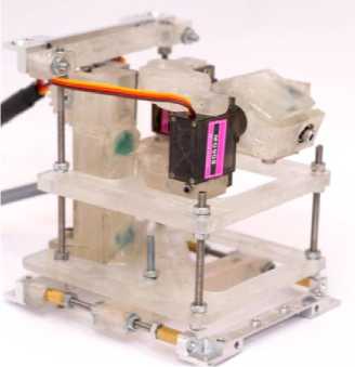
Fig. 1. Mechatronic and multiaxis modules in the assembly
transmitting antenna). The disclosed antenna system is one of the most frequent mechatronic payloads of small spacecrafts [8].
The module is designed for linear movement over a distance of at least 50 mm. An mg90s servo with an angle of 180 o was chosen to extend the rail. To control the position of the rail, feedback sensors developed at our university were introduced into the design of the mechatronic module. A feature of the sensors is the possibility of changing the response distance depending on the resistance value of the resistor installed on the sensor board.
The design and calculation of all payload nodes were carried out using special software [9]. The created 3D models of the parts were manufactured using additive technologies using an FDM printer. The final view of both payloads in the assembly is shown in Fig. 1.
Рис. 1. Мехатронный и многостепенной модули в сборке
The structure of the interaction of the payload with the platform
The developed payload was integrated into the OrbiCraft-Pro 3U CubeSat platform. The block diagram of the interaction of the payload and the on-board digital computing module (BDCM) of the platform from the company "Sputnix" is shown in Fig. 2. The principle of operation is as follows: the inclusion of the ESP32 microcontroller (MC), which controls the multi–stage EM and the mechatronic module, occurs in the main BDCM - Raspberry Pi CM3. After switching on the MC, a control signal of pulse-width modulation (PWM) is generated, which is supplied to the servomotors of the modules. The signal causes the servomotors to rotate and sets the modules in motion. For a two-stage platform, the output control value is the angles of rotation of the platform along two axes, for a mechatronic module, this value is the position of the rail. The camera, located on a two-stage platform, is connected directly to the BDCM via CSI. This allows you to take pictures at any time, without requiring the inclusion of ESP and additional communication of ESP with the BDCM. Separately, the power supply module is controlled via the MC STM32L053R8T6. Such a separation in the control of the payload allows you to switch the main power system to power from the supercapacitor module, which allows you to test the mechanical load from different sources.
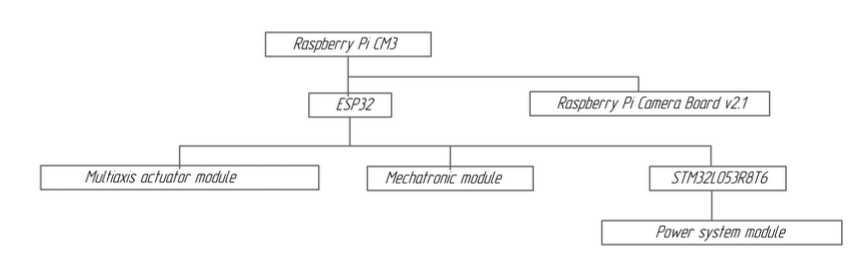
Fig. 2. The structural scheme of interaction of payload with board computer
Рис. 2. Структурная схема взаимодействия ПН с БЦВМ
Fig. 3 describes the interaction of the spacecraft modules. On the main CAN (Controller Area Network) bus, the following communicate: platform controller, on-board ultrashort wave transceiver, Raspberry Pi CM3 BDCM, controllers of orientation systems and power supply. A ground-based electronic computing machine (computer) with a set of specialized software is also part of the CAN bus of the device. The BDCM is connected via the UART interface to the MC payload ESP32. The ESP generates a PWM signal to control the servos and adjusts the position of the mechatronic EM via the feedback channel. Monitoring of the backup power supply mode based on supercapacitors is carried out using a discrete output.
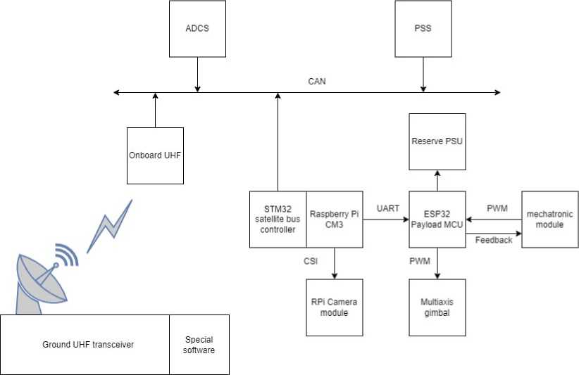
Fig. 3. Scheme of interaction of the spacecraft modules
Рис. 3. Схема взаимодействия модулей КА
To ensure shared access of modules to the bus, a stack of protocols of different levels of abstractions is used. The data transfer protocol is based on the CAN protocol. It describes the physical and channel layers in the standard OSI model (The Open Systems Interconnection model). This protocol is one of the most popular and reliable ways of interaction of small spacecraft blocks [10]. To ensure the transmission of long messages by the addressing system between the source and receiver, the channel layer is expand- ed by the higher-level UniCAN protocol (universal CAN bus), described below. Application-level data is transferred over the UniCAN protocol. Each packet contains the address of the message source and the address of the receiver, which are transferred to the CAN frame identifier field.
The protocol supports the transmission of messages in three formats – short messages, long messages and error messages. Short messages will allow you to transmit data of no more than 6 bytes in length. They are transmitted in one CAN frame.
The length of the data is determined by the length of the frame transferred to the DLC field (Data Length Code-the length code of the data field) of the CAN frame, minus two bytes for transmitting the message identifier. The "data" field of short messages is always zero. The transmission correctness control is provided by the checksum of the CAN protocol.
The structure of the CAN frame data field is shown in Table 1.
Table 1
CAN frame data field when transmitting a short UniCAN message
|
Bytes of the CAN frame data field |
||||||
|
0 1 1 |
2 |
3 |
4 |
5 |
6 |
7 |
|
ID message ID |
Data 0 |
Data 1 |
Data 2 |
Data 3 |
Data 4 |
Data 4 |
Long messages consist of several CAN frames.
The general transmission structure using the example of a 26-bit message is shown in Table 2.
Table 2
The general structure of the message on the bus
|
Start Command |
Data 0..7 |
Data 8..15 |
Data 16..23 |
Data 24...26+CRC |
|
0xFFFE MSG_ID Len |
CRC |
The format of the service command for transmitting the beginning of a long message is shown in Table 3.
Table 3
Format of the long message start command
|
Bytes of the CAN frame data field |
||
|
0 1 1 |
2 1 3 |
4 1 5 |
|
Start ID 0xFFFE |
Message ID(MSG_ID) |
Package Length (Length) |
In response to errors occurring when receiving the UniCAN message, error messages can be sent, the format of which is shown in Table 4.
Table 4
Error message format
|
Bytes of the CAN frame data field |
||
|
0 1 1 |
2 1 3 |
4 1 5 |
|
Error Message ID 0xFFFF |
Error Message ID (Failed_MSG_ID) |
Error Code |
Development of the payload control board
The board was developed in two stages: mock-up and production of a flight sample. At the first stage, all the necessary components were connected by wires to confirm the correct operation of all components and software development. At the second stage, a flight sample of the board for integration into the device was manufactured and tested.
This board works together with the power subsystem, thanks to which it is possible to switch the power supply of the mechatronic module in the following modes: power from the on-board network, batteries, supercapacitors and charging of batteries or supercapacitors. A simplified schematic diagram of the board is shown in Fig. 4. This functionality allows you to test various servo power sources during flight. Switching power modes is performed using transistor switches.
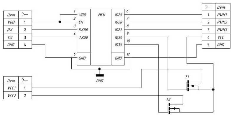
Fig. 4. Schematic diagram of the payload control board
Рис. 4. Принципиальная схема платы управления полезной нагрузкой
The main task of the board is to generate pulse width modulation signals for controlling servos, as well as validating their correct position using feedback from the on-board sensor network. The need for development is dictated by stricter time requirements for the parameters of the generated signal when implementing a soft start and stop mechanism, which are not achievable when using hardware from the on-board system due to their high sampling error. Thanks to the developed board, an algorithm for smooth start and stop of servos was provided, which more efficiently consumes a small energy resource of the small spacecraft and increases the service life of the mechatronic module.
The control board is connected to the on-board system via a USB interface via a UART converter. The on-board system is a Raspberry Pi CM3 microcomputer, which can be connected via a radio channel from the Earth using the telnet interface. The payload control board with the power subsystem can be seen in Fig. 5.
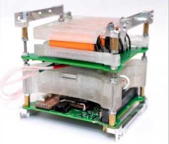
Fig. 5. Payload control board with power supply subsystem
Рис. 5. Плата управления полезной нагрузки с подсистемой питания
Development of a management system
The program for controlling the mechatronic module for the payload board with the ESP32-S microcontroller supplies power, controls the servos and reads the states of the end caps.
The soft-start algorithm for servos is implemented by integrating the set rotation angle to obtain intermediate states. Then, the rotation speed is limited and performed alternately by reference points.
To control the mechatronic module, three commands were written: sliding the rail, extension and a cycle consisting of sliding and extending with a delay of 2 seconds between commands. The commands were implemented with checking the current position by sensors, if the rail is in a half-extended state, then before executing some of the commands it will slide into its original position. This is necessary to avoid the loss of the rail from the structure.
To control the payload board, a program for the Windows operating system (OS) was originally developed. A similar decision was made to be able to test the control of the payload via the COM-port (communications port) of the computer. Subsequently, the program was ported to an on-board microcomputer with Linux OS, where communication with the payload control board was successfully worked out.
The software has implemented the possibility of extended logging to track code execution and identify problems that arise during the execution of commands. The application provides detailed in- formation about the status of the module, including information about any errors or exceptions that may have occurred.
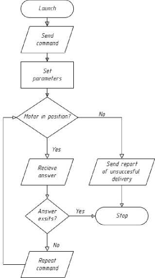
Fig. 6. Algorithm of the payload operation
One of the key advantages of this approach is that it allows you to detect and diagnose problems in real time. This is especially important when working with complex systems, in particular those operating in near-Earth space, because it allows you to quickly identify and fix problems before they can cause significant damage to the device. Logging allows you to track the history of the module, which can be invaluable when trying to diagnose and fix problems that have arisen in the past. It can also help identify patterns or trends that may indicate potential problems in the future. Another important function of the developed software is that it can be used to create detailed reports that can be used in the development of other devices.
The stability of working with the on-board system was enhanced by entering a checksum of commands. If the checksum does not match or incorrect parameters of the rotation angles and/or unacceptable rotation speeds are set, the microcontroller signals this to the on-board system to repeat the command transmission for execution. A simplified algorithm for working with the payload is shown in Fig. 6.
Рис. 6. Алгоритм работы с полезной нагрузкой
Test results
Payload tests were carried out at the Voenmeh Engineering Center, which has specialized equipment for testing various technical products, including those developed for operation in extreme conditions, for example, such as outer space [11]. In particular, thermal vacuum, vibration tests on three axes and shock tests of the payload design were carried out.
After testing, design flaws were identified and corrected. After completion, the payload successfully passed the tests and went to Sputnix, where additional testing was carried out taking into account the characteristics of the launch vehicle planned for the launch of the satellite. A photo of the device testing is shown in Fig. 7. After testing, all materials proved to be resistant to space flight conditions.
A photo of the device with a payload after testing is shown in Fig. 8.
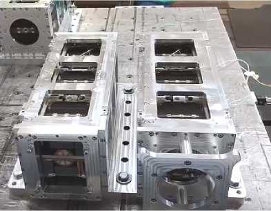
Fig. 7. Conducting tests on the basis of SPUTNIX LLC
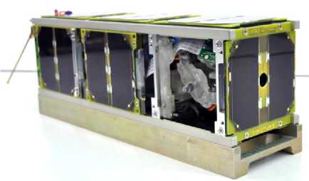
Fig. 8. SXC3-2110 VOENMEH spacecraft before launch
Рис. 7. Проведение испытаний на базе ООО «Спутникс»
Рис. 8. МКА SXC3-2110 VOENMEH перед запуском
Communication with the device
After establishing two - way communication with the spacecraft through the ground station of the Siberian State University named after M. F. Reshetnev began the process of working with payloads [12].
The spacecraft is connected to Earth by a UHF radio line at a frequency of 436 MHz at a speed of 2400 baud. The USP (Unified Sputnix Protocol) protocol with forward error correction (FEC) and interference–resistant Reed-Solomon coding is used, which meets the requirements of CCSDS 131.0-B-3 with respect to synchronization and transmission of telemetry data [13]. The on-board transceiver serves as a bridge between the ground station and the internal CAN bus of the device. The ground is also part of the CAN bus, for which the UniCAN server is launched on the control computer, which interacts with the transceiver and specialized HCCA (Houston Control Center Application) and Houston Telnet programs. HCCA is used to view telemetry data from the device and issue control actions to the nodes of the spacecraft platform. With the help of Houston Telnet, communication is carried out with a Raspberry Pi CM3-based BDCM, to which payload modules are connected. The regular telemetry data package contains information that allows you to quickly assess the state of the spacecraft (Table 5). Upon request, additional information can be transmitted from the Earth, and the telnet mode of access to the BDCM can also be enabled [14]. In the Telnet access mode, the BDCM is controlled by transmitting data from the text console OS BDCM inside the CAN frame to the UHF transceiver and back. In this mode, you can work with peripheral devices, such as the payload controller and the onboard camera. Image files and other experimental results are also obtained from the memory of the BDCM via Telnet access. The transfer of images and other large files is carried out by dividing them into small parts using the tar archiver and their sequential transmission.
Table 5
Regular telemetry data
|
Parameter |
Unit of measurement |
Example of data from the spacecraft |
|
Voltage SB1 |
mV |
13 |
|
Voltage SB2 |
mV |
7 |
|
Voltage SB3 |
mV |
11 |
|
Current SB1 |
mA |
1 |
|
Current SB2 |
mA |
2 |
|
Current SB3 |
mA |
0 |
|
Battery current |
mA |
–472 |
|
Current channel 1 |
mA |
475 |
|
Current channel 2 |
mA |
29 |
|
Current channel 3 |
mA |
0 |
|
Current channel 4 |
mA |
0 |
|
Battery temperature 1 |
degree Celsius |
–2 |
|
Battery temperature 2 |
degree Celsius |
–2 |
|
Battery temperature 3 |
degree Celsius |
–2 |
|
Battery temperature 4 |
degree Celsius |
–2 |
|
Status flags |
– |
Low battery life |
|
Battery voltage |
mv |
7736 |
|
TM packet counter |
– |
1890 |
|
Time by on-board clock |
dd.mm.yyyy hh:mm:cc |
10.01.2023 15:59:31 |
|
PSS reset counter |
– |
223 |
|
PSS Flags |
– |
4 |
|
PA temperature |
degree Celsius |
4 |
|
Radio temperature |
degree Celsius |
3 |
|
Signal strength from the Earth |
dBm |
104 |
|
Signal strength at rest |
dBm |
131 |
|
Direct transmission power |
dBm |
32 |
|
Reflected power |
dBm |
10 |
|
UHF TRX reset counter |
– |
130 |
|
UHF time |
dd.mm.yyyy hh:mm:cc |
10.01.2023 15:59:32 |
|
Time since last reset |
ms |
18951 |
|
UHF consumption current |
mA |
29 |
|
UHF voltage |
mV |
7735 |
Conclusion
The payload was developed and tested with software for its control system. The created payload was tested on a vibration stand for shock loads and passed thermal vacuum tests, after which it was finalized and successfully tested. After that, the payload is integrated into the existing OrbiCraft Pro software and hardware complex, taking into account all the requirements of the launch operator. The spacecraft was launched together with other satellites on the Soyuz 2.1b launch vehicle on August 9, 2022 from the Baikonur Cosmodrome [15; 16]. Two-way communication with the Cyclops satellite has been established . According to calculations, the satellite should work in orbit for a year, during which it is planned to attract schoolchildren and students to perform laboratory work and master classes, conduct comprehensive testing and research during the life of the device of the modules being developed, and also conclude that the proposed technical solutions for integration into large-sized spacecraft and complexes are appropriate. Currently, active work is underway with the satellite through the mission control center and writing guidelines for conducting space experiments.
References Development of the CYCLOPS CubeSat payload
- Nanosats Database. Available at: https://www.nanosats.eu (accessed:10.01.2023).
- CDS. CubeSat Design Specification. Rev. 14.1 California Polytechnic State University, 2022.
- Poghosyan A., Golkar A. CubeSat evolution: Analyzing CubeSat capabilities for conducting science missions. Progress in Aerospace Sciences. 2017, Vol. 88, P. 59–83. Doi 10.1016/j.paerosci.2016.11.002.
- Khohlov A. V. [Educational space project space-pi]. Materialy XIV Mezhdunarodnoj nauchno-prakticheskoj konferencii [Materials of the XIV International scientific-practical conference], Star City, 2021, P. 384–386 (In Russ.).
- Konstruktor sputnika “OrbiCraft” [OrbiCraft satellite kit]. Available at: http://www.orbicraft. sputnix.ru/doku.php (accessed:10.01.2023).
- Simonov V. L. [Application of Cubesat nanosatellite (Cubesat) development in educational pro-cess ] Sovremennye informacionnye tekhnologii v obrazovanii, nauke i promyshlennosti: Sbornik tru-dov. XHI Mezhdunarodnaya konferenciya [XXI International conference]. Moscow, 2022, P. 81–84 (In Russ.).
- Tishkov A. I., Konoplev Yu. V., Yuev A. A. [Prospects for the application of a combined energy storage device for space applications]. Siberian Aerospace Journal. 2022, Vol. 23, No. 1, P. 105–115 (In Russ.). Doi: 10.31772/2712-8970-2022-23-1-105-115.
- Sining L., Panagiotis T., Raad R. et al. A Survey on CubeSat Missions and Their Antenna De-signs. Electronics. 2022. No. 11. P. 1–46. Doi: 10.3390/electronics11132021.
- Egorov O. D. [Mechatronic approach in designing integrated mechatronic modules]. Vestnik MSTU "Stankin". 2018, Vol. 44, No. 1, P. 101–105 (In Russ.).
- Scholz Artur, Hsiao Tian-Hao, Juang Jer-Nan, Cherciu Claudiu. Open source implementation of ECSS CAN bus protocol for CubeSats. Advances in Space Research. 2017. No. 62. Doi:62. 10.1016/j.asr.2017.10.015.
- BGTU “Voenmeh” zavershil izgotovlenie poleznyh nagruzok dlya malyh kosmicheskih appa-ratov [BSTU “Voenmeh” completed the development of payloads for small spacecraft CubeSat]. Available at: https://www.voenmeh.ru/news/science/cubesat-development (accessed:10.01.2023).
- Studencheckiy center upravlenia poletom [Student’s misson control center]. Available at: https://sat.sibsau.ru/ (accessed: 10.01.2023).
- TM Synchronization and Channel Coding – CCSDS. Available at: https://public. ccsds.org/Pubs/131x0b4.pdf (accessed:10.01.2023).
- Bogomolov V. V., Bogomolov A. V., Dement’ev Y. N. et al. [A scientific and educational space experiment on the SiriusSat-1,2 satellites]. Moscow University Physics Bulletin. 2020, No. 6, P. 125–134 (In Russ.). Doi: 10.3103/S0027134920060077.
- SPUTNIX – For radio amateurs. Available at: https://sputnix.ru/en/satellites-sputnix/for-radioamateurs (accessed:10.01.2023).
- Voenmehovskiy sputnik v kosmose [Voenmeh’s satellite in space]. Available at: https://www.voenmeh.ru/news/science/cubesat (accessed:10.01.2023).
